Dynamic Viewport-Adaptive Rendering in Distributed Interactive VR Streaming
←
→
Page content transcription
If your browser does not render page correctly, please read the page content below
Aalto University
School of Science
Master’s Programme in Computer, Communication and Information Sciences

Thomas van Gemert

Dynamic Viewport-Adaptive Rendering
in Distributed Interactive VR Streaming:
Optimizing viewport resolution under latency
and viewport orientation constraints

Master’s Thesis
Espoo, September 19, 2019

Supervisor:     Prof. Antti Ylä-Jääski
Advisor:        Dr. Matti Siekkinen
Aalto University
School of Science
Master’s Programme in Computer, Communication and   ABSTRACT OF
Information Sciences                              MASTER’S THESIS
Author:             Thomas van Gemert
Title:
Dynamic Viewport-Adaptive Rendering in Distributed Interactive VR Streaming:
Optimizing viewport resolution under latency and viewport orientation con-
straints
Date:               September 19, 2019                       Pages: 71
Major:              Computer Science                         Code: SCI3042
Supervisor:         Prof. Antti Ylä-Jääski
Advisor:            Dr. Matti Siekkinen
In streaming Virtual Reality to thin clients one of the main concerns is the mas-
sive bandwidth requirement of VR video. Additionally, streaming VR requires a
low latency of less than 25ms to avoid cybersickness and provide a high Quality
of Experience. Since a user is only viewing a portion of the VR content sphere
at a time, researchers have leveraged this to increase the relative quality of the
user viewport compared to peripheral areas. This way bandwidth can be saved,
since the peripheral areas are streamed at a lower bitrate. In streaming 360◦
video this has resulted in the common strategy of tiling a video frame and deliv-
ering different quality tiles based on current available bandwidth and the user’s
viewport location. However, such an approach is not suitable for real-time Inter-
active VR streaming. Furthermore, streaming only the user’s viewport results in
the user observing unrendered or very low-quality areas at higher latency values.
In order to provide a high viewport quality in Interactive VR, we propose the
novel method of Dynamic Viewport-Adaptive Rendering. By rotating the frontal
direction of the content sphere with the user gaze, we can dynamically render
more or less of the peripheral area and thus increase the proportional resolution
of the frontal direction in the video frame. We show that DVAR can successfully
compensate for different system RTT values while offering a significantly higher
viewport resolution than other implementations. We further discuss how DVAR
can be easily extended by other optimization methods and discuss how we can
incorporate head movement prediction to allow DVAR to optimally determine
the amount of peripheral area to render, thus providing an optimal viewport
resolution given the system constraints.
Keywords:           Virtual Reality, Cloud, Streaming, VR, Optimization, Day-
                    dream, Rendering, Latency, Head Movement Velocity, Cloud
                    Gaming, Interactive VR, Mobile, Resolution, Quality of Ex-
                    perience
Language:           English

                                       2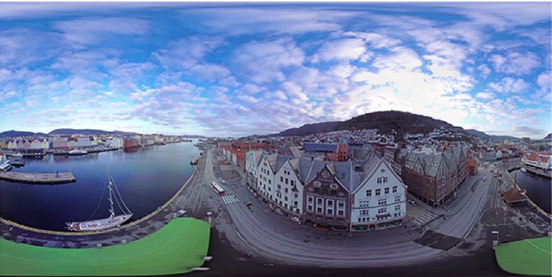
Acknowledgements

I would like to thank the CloudXR1 team at Aalto University, in particular
Matti Siekkinen, Teemu Kämäräinen and Olavi Mertanen for their insight
and support during the development of this work. I furthermore extend my
thanks to my supervisor, Prof. Antti Ylä-Jääski for his support, Gazi Illahi
for several fruitful discussions and Prof. Antti Oulasvirta for his inspiration
and support during my education.

Espoo, September 19, 2019

Thomas van Gemert

  1
      https://cloudxr.cs.aalto.fi

                                      3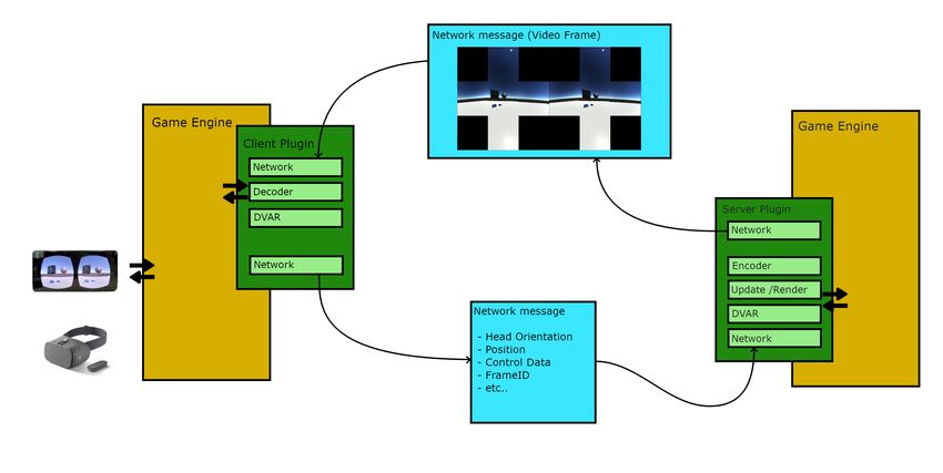
Abbreviations and Acronyms

AR      Augmented Reality
DASH    Dynamic Adaptive Streaming over HTTP
DoF     Degrees-of-Freedom
DVAR    Dynamic Viewport-Adaptive Rendering
FoV     Field-of-View
HMD     Head-Mounted Display
JVET    Joint Video Experts Team
MR      Mixed Reality
QEC     Quality Emphasis Center
QER     Quality Emphasis Region
QoE     Quality of Experience
RTT     Round-Trip Time
VR      Virtual Reality
VRE     Virtual Reality Environment
Wi-Fi   Radio technologies for WLAN

                     4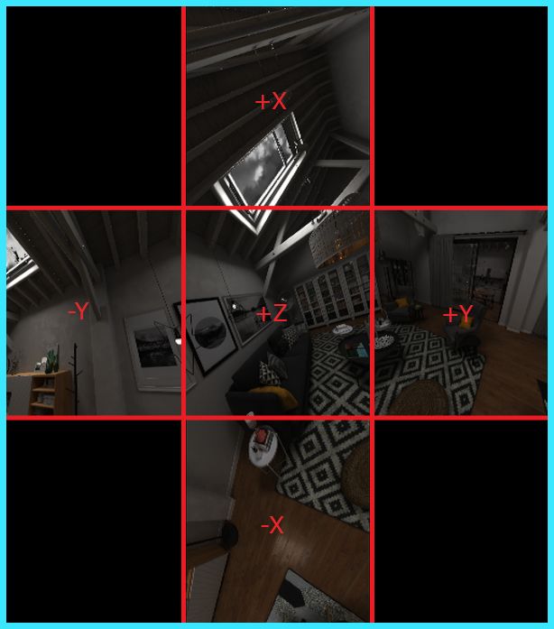
Contents

Abbreviations and Acronyms                                                                                         4

1 Introduction                                                             7
  1.1 Problem Statement . . . . . . . . . . . . . . . . . . . . . . . . 9
  1.2 Scope of the Thesis . . . . . . . . . . . . . . . . . . . . . . . . 10
  1.3 Structure of the Thesis . . . . . . . . . . . . . . . . . . . . . . 11

2 Background                                                                                                      12
  2.1 Virtual Reality . . . . . . . . . . . . . . . . . . . .                             .   .   .   .   .   .   12
  2.2 Virtual Reality Streaming . . . . . . . . . . . . . .                               .   .   .   .   .   .   14
  2.3 Head Orientation and Projection Mapping . . . . .                                   .   .   .   .   .   .   17
  2.4 Related work: 360◦ Video Streaming . . . . . . . .                                  .   .   .   .   .   .   19
  2.5 Related work: Real-time Interactive VR Streaming                                    .   .   .   .   .   .   20

3 System Architecture                                                      23
  3.1 Server . . . . . . . . . . . . . . . . . . . . . . . . . . . . . . . 24
  3.2 Client . . . . . . . . . . . . . . . . . . . . . . . . . . . . . . . 26

4 Dynamic Viewport-Adaptive
  Rendering (DVAR)                                                                                                28
  4.1 Idea . . . . . . . . . . . . . . . . . . . . .                  .   .   .   .   .   .   .   .   .   .   .   28
  4.2 Implementation . . . . . . . . . . . . . . .                    .   .   .   .   .   .   .   .   .   .   .   30
  4.3 Optimization . . . . . . . . . . . . . . . .                    .   .   .   .   .   .   .   .   .   .   .   31
      4.3.1 Compensating for System Latency                           .   .   .   .   .   .   .   .   .   .   .   32
      4.3.2 Head Movement . . . . . . . . . . .                       .   .   .   .   .   .   .   .   .   .   .   35

5 Experiment Setup                                                                                                38
  5.1 Measurements . . . . . . . .    .   .   .   .   .   .   .   .   .   .   .   .   .   .   .   .   .   .   .   38
      5.1.1 Unsuccesful Frames .      .   .   .   .   .   .   .   .   .   .   .   .   .   .   .   .   .   .   .   40
      5.1.2 Unrendered Area . .       .   .   .   .   .   .   .   .   .   .   .   .   .   .   .   .   .   .   .   40
      5.1.3 Viewport Resolution       .   .   .   .   .   .   .   .   .   .   .   .   .   .   .   .   .   .   .   42

                                     5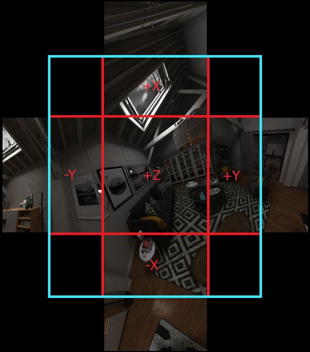
5.1.4 Bandwidth, Latencies and System Performance                     .   .   .   .   42
   5.2   Materials & Apparatus . . . . . . . . . . . . . . . . . .             .   .   .   .   43
   5.3   Emulating Head Movement . . . . . . . . . . . . . . .                 .   .   .   .   43
         5.3.1 Recording the Head Traces . . . . . . . . . . . .               .   .   .   .   43
         5.3.2 Emulating the Head Traces . . . . . . . . . . .                 .   .   .   .   44
   5.4   Reference Conditions & Encoding Parameters . . . . .                  .   .   .   .   44
   5.5   Procedure . . . . . . . . . . . . . . . . . . . . . . . . .           .   .   .   .   45

6 Results                                                                                      47
  6.1 Overall Performance . . . . .        . . . . .   . . . . . . .   .   .   .   .   .   .   47
      6.1.1 Viewport Resolution .          . . . . .   . . . . . . .   .   .   .   .   .   .   47
      6.1.2 Bandwidth . . . . . . .        . . . . .   . . . . . . .   .   .   .   .   .   .   48
      6.1.3 Unsuccessful Frames &          Effective   Bandwidth       .   .   .   .   .   .   49
      6.1.4 System Performance .           . . . . .   . . . . . . .   .   .   .   .   .   .   50
  6.2 Per-user Analysis . . . . . . .      . . . . .   . . . . . . .   .   .   .   .   .   .   50
      6.2.1 User 1 . . . . . . . . .       . . . . .   . . . . . . .   .   .   .   .   .   .   50
      6.2.2 User 2 . . . . . . . . .       . . . . .   . . . . . . .   .   .   .   .   .   .   52
      6.2.3 User 3 . . . . . . . . .       . . . . .   . . . . . . .   .   .   .   .   .   .   54
      6.2.4 User 4 . . . . . . . . .       . . . . .   . . . . . . .   .   .   .   .   .   .   55
      6.2.5 User 5 . . . . . . . . .       . . . . .   . . . . . . .   .   .   .   .   .   .   57
  6.3 Reference Conditions . . . . .       . . . . .   . . . . . . .   .   .   .   .   .   .   58
  6.4 Discussion . . . . . . . . . . .     . . . . .   . . . . . . .   .   .   .   .   .   .   59

7 Future Work                                                                                  63

8 Conclusions                                                                                  65

Bibliography                                                                                   65

                                       6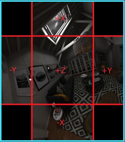
Chapter 1

Introduction

In recent years Virtual Reality (VR) has seen a significant increase in atten-
tion from researchers, market, hardware/software developers and consumers.
A recent report predicts that the VR market is expected to reach a value
of $26.89 billion in 2022 [52]: a massive increase from $2 billion in 2016.
Although VR research is not ”new” as such, and goes back to the 1980’s, re-
cent developments and releases of high-end consumer-grade Head-Mounted
Displays (HMD’s) such as the HTC Vive and Oculus Rift have have made
both development and research of VR more accessible. VR content comes in
many forms nowadays, but mainly as either video games/computer-generated
3D imagery or 360◦ video (otherwise known as panoramic or omnidirec-
tional video). In order to view VR content an HMD is required, which is
a binoculars-like device that tracks head movement to match the viewport1
of the virtual environment to the direction a user is looking. Apart from high-
end and expensive HMD’s such as the Oculus Rift and HTC Vive, low-end
HMD’s have also been published for mobile devices such as Google Daydream,
Google Cardboard or Samsung GearVR. In these HMD’s the smartphone is
used to take care of the tracking and display of the Virtual Reality Environ-
ment (VRE), while the HMD provides the lenses necessary for viewing the
VRE in 3D. Both a challenge and a benefit of these mobile solutions is that
they are untethered, and thus do not require a separate high-end desktop
PC to render VR content. Furthermore, manufacturers such as Oculus and
Lenovo have presented stand-alone mobile HMD’s such as the Oculus Go,
   1
    The viewport is the area of a VR image that the user can see at a given moment. In
traditional video this is simply all parts of the video visible on screen. In VR video, as
the user is watching part of a sphere through the HMD’s lenses, this is the part that the
user sees through the lenses. The size of the viewport depends on the field-of-view of the
HMD, expressed in degrees. Hence, the viewport size does not depend on the resolution
of the video or the physical size of the HMD’s display.

                                            7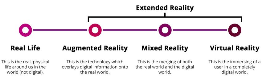
CHAPTER 1. INTRODUCTION                                                               8

Oculus Quest or Lenovo Mirage Solo that combine the features of high-end
HMD’s with full mobility, based on a mobile chipset.
    Both mobile smartphone-based and stand-alone HMD’s offer benefits in
viewing VR content because they do not require expensive supporting hard-
ware, an array of cables or a restricted usage area. These mobile HMD’s
either render the content locally or receive it over a wireless connection such
as Wi-Fi or LTE. Although smart devices are getting increasingly more pow-
erful and are catching up fast to modern PC’s in terms of computing power,
their performance is still limited and is likely to remain limited compared
to high-end PC’s since their primary objectives in performance management
differ: smart devices generally prioritize power savings and efficiency, while
PC’s offer a much higher performance. As such, mobile devices are only
capable of rendering low-quality 3D images. Streaming VR content over
a wireless connection presents a possible solution to provide high quality
graphics, as the local device only has to display it on screen and track user
and controller position. However, the bandwidth of wireless connections is
limited and prone to more or less severe fluctuations.
    Due to the nature of VR content the bandwidth requirements of streaming
VR content are several factors higher than those of streaming traditional 2D
video: in a virtual environment a user’s point of view resides inside a sphere,
while the VR content is projected to the inside of the sphere. This gives the
user a full 360◦ × 180◦ Field of View2 (FoV). This means that, in order to
stream the full spherical content, the transmission of a 360◦ video consumes
4-6x the bandwidth of a regular video with the same resolution [13], [51],
easily reaching 12K pixels resolution for common HMD’s. However, the user
is only looking at a part of the sphere at a given time (the viewport). In
order to present the viewport in sufficient quality to maintain a good Quality
of Experience (QoE), the viewport resolution is generally at least the native
resolution of the HMD, for example 1600x1440 pixels per eye for the recently
released Oculus Quest. Because of the massive resolution of VR content
and the limited bandwidth of current wireless connections, it is infeasible to
stream any VR content of such a connection. Due to encoding technology
such as H.264 (AVC), H.265 (HEVC) or VP9 the bandwidth requirement
can be decreased, but it remains significantly higher than that of traditional
video. Additionally, VR streaming requires anew video frame to be displayed
at a very low latency for a smooth experience, which requires high Frames
   2
     Field-of-View (FoV) refers to the area a user can see, either through his eyes or a
device. It is usually measured in degrees. For example, 360◦ video provides a potential
360◦ FoV, as the vdeo contains content for each possible viewing direction. However, a
typical HMD might offer only a 100◦ FoV, allowing the user to see 100◦ worth of content
at a time.
CHAPTER 1. INTRODUCTION 9
Per Second (FPS) rendering, further increasing the bandwidth requirement.
1.1 Problem Statement
A central theme in the VR research community in recent years has been:
”How can we further reduce the bandwidth requirements of VR streaming
without decreasing the Quality of Experience?”. Even with the promise
of new Wi-Fi technology, server technology or 5G networking technology,
HMD’s are expected to also support higher resolutions to further increase
the potential visual quality. However much bandwidth becomes available
in the future, we can expect the receiving end to match it in demand, so
the problem of determining an efficient streaming solution for VR remains
(not unlike traditional video streaming optimization). A popular strategy
is to leverage the fact that a user only views one portion of a VR video
at a time, thus giving content delivery systems the opportunity to deliver
higher quality in that area, while limiting the bandwidth requirement for the
peripheral areas. Recently many methods for this have utilized the recent
MPEG-DASH streaming protocol: by dividing a video into separate tiles and
training a content delivery model on head traces from users watching 360◦
video a quality level of a tile can be determined, based on it’s location w.r.t.
the user’s viewport and the available bandwidth.
Primary downsides of this approach are the required extra storage ca-
pacity on the server side, the non-trivial determination of how to generate
the tiles and quality levels, or how to implement viewport awareness. Most
importantly, however, is that most of these works focus on streaming 360◦
video, instead of streaming a VR application such as a game (much like in
traditional cloud gaming). Streaming Interactive VR requires taking into ac-
count the effect of interactivity and requires real-time changes to any dynamic
quality variations. This excludes tiling and other pre-generated video based
solutions as the additional overhead of creating tens of different versions of
tiles of each video frame would violate the latency requirement.
In a lesser way researchers have begun investigating VR streaming sys-
tems: due to the strict latency requirements it is non-trivial to set up a VR
streaming system that delivers the required QoE. Given that the motion-
to-photon latency should be below 10-25ms [7], [35], a server has to render,
encode and transmit a frame within, say, 10ms to give the client 6ms to
present the frame. Separately, work has been published on improving wire-
less network connectivity and hardware performance for VR streaming, but
the work on combining these new technologies into a VR system that can
support fully interactive VR at high resolutions is limited. The task is fur-CHAPTER 1. INTRODUCTION 10
ther complicated by the fact that mobile devices such as smartphones, a key
target for VR streaming, have limited processing power and are bound by
power-saving policies.
1.2 Scope of the Thesis
In this work we present a novel viewport-adaptive rendering solution for VR
streaming. By rotating the frontal direction of the VR video sphere with
the gaze of the user, we can dynamically increase or decrease the amount
of peripheral area to render since this area is not visible to the user. Less
peripheral area rendered not only enables lower rendering times, but leaves
room on a video frame to increase the proportional resolution of the frontal
direction. Our solution optimizes the resolution in the viewport by rendering
only the viewport location and a surrounding area based on the current net-
work conditions and head orientation parameters. By utilizing the remaining
available bandwidth to increase the viewport resolution we increase the QoE
while simultaneously compensating for the effects of system latency. Our
solution, which will be introduced in Chapter 4, is designed for streaming
Interactive VR content, such as cloud-based VR gaming, but can also sup-
port 360◦ video streaming. The system is designed for live streaming of
computer-generated images, such as games or simulations, and streams these
at an optimal quality level to a standalone or smartphone-based client device.
The amount of peripheral area to render critically depends on the system’s
response time and the user’s head movement velocity. Our solution dynam-
ically adapts itself to the system’s Round-Trip Time (RTT) (time before a
requested frame is rendered on the client) and the user’s head movement
velocity to offer exactly the right amount of peripheral area to avoid showing
any unrendered area. This way we can maximize the viewport resolution
while offering a completely transparent experience to the user. Because we
change the amount of peripheral area to render at render time (i.e. before en-
coding), our solution can easily be combined with existing approaches such
as tiling, improved encoding, head movement prediction, gaze prediction,
optimized software algorithms for rendering and coding, etc. Furthermore,
our solution comprises a low-impact, high-level software solution which al-
lows for easy improvements as hardware and technology support allow for
even higher resolutions and frame rates. We show that Dynamic Viewport-
Adaptive Rendering (DVAR) is capable of precisely reacting to changes in
system RTT, and that DVAR requires less bandwidth than comparative im-
plementations while offering a significantly higher viewport resolution.CHAPTER 1. INTRODUCTION 11 1.3 Structure of the Thesis This work is organized as follows: we first elaborate on the concept of vir- tual reality, VR streaming the different factors involved and related works in Chapter 2: Background. We then present a prototype streaming sys- tem in Chapter 3: System Architecture. Our Dynamic Viewport-Adaptive Rendering proposal is presented in the likewise-named Chapter 4, after which we set up an experiment to evaluate DVAR’s performance. The experiment set-up is discussed in Chapter 5: Experiment Setup and the results of our experiments are presented and discussed in Chapter 6: Results. In the same chapter we furthermore discuss future improvements. Finally, we summarize our work in Chapter 8: Conclusions.
Chapter 2

Background

Virtual Reality is defined by the Oxford dictionary as ”The computer-generated
simulation of a three-dimensional image or environment that can be inter-
acted with in a seemingly real or physical way by a person using special
electronic equipment, such as a helmet with a screen inside or gloves fitted
with sensors” [48]. In other words, Virtual Reality can refer to the three-
dimensional computer generated environment of a video game, in which the
user is immersed as if they were physically present in the virtual environ-
ment by means of a (head-mounted) stereoscopic display, binaural audio and
simulation of physical hand, head and leg positions in the virtual world.
VR revolves around making a user believe they are physically present in a
non-physical environment, by substituting real-world input to the senses by
artificially created ones.

2.1     Virtual Reality
Although recently VR and it’s related technologies have seen a massive influx
of interest, the concept may be older than the computer itself [49]. The
first devices and use cases that are related to how we know VR nowadays
come from the 70’s and 80’s, when NASA’s Ames Research Center set up a
Virtual Interactive Environment Workstation based on a headset that offered
stereoscopic imagery and a convincingly large Field-of-View [49]. During this
time also game console manufacturers such as SEGA and Nintendo released
VR devices that were capable of displaying stereoscopic images. It should be
noted however, that in this time VR did not exclusively refer to the HMD-
based idea: in fact, still to this day it encompasses any virtual environment
that may be convincing enough to immerse the user. This includes, for
example: driving and flying simulators, projection based (”holodeck style”)

                                     12
CHAPTER 2. BACKGROUND 13
Figure 2.1: An overview of the XR spectrum containing Augmented Real-
ity, Mixed Reality and Virtual Reality technologies in increasing order of
immersion into a virtual environment. Image from [37].
VR rooms and telepresence solutions. For a further read on the interesting
history of Virtual Reality, see for example [1], [42], [49]. Nowadays VR is
part of the umbrella term ”eXtended Reality” (XR), which further includes
Augmented Reality (AR) and Mixed Reality (MR) technologies (see Figure
2.1). Whereas VR offers full immersion in a completely virtual environment,
AR adds virtual elements to the real world, to be viewed using a camera that
combines real world images and virtual ones into the same view. MR further
combines virtual and real artefacts by allowing them to interact with each
other.
The recent influx of interest in Virtual Reality in academia, commercial
and consumer markets came around the the introduction of Facebook’s Ocu-
lus Rift, the HTC Vive and Sony Playstation VR headsets in 2012-2016.
These headsets were developed for the consumer market and offered a high
quality immersive experience at an affordable cost. Many more VR headsets
were to follow, with one of the latest being the Valve Index VR kit released
in June 2019. These headsets are all tethered: they require to be connected
to a computer at all times to transmit visual data over a multi-Gbps cable
and controller and tracking information over USB. However, in 2015 Google
introduced Cardboard, a DIY headset that allowed users to place a capa-
ble smartphone in the headset and watch stereoscopic content through the
headset’s lenses. In 2016, Daydream View was released: a more mature and
comfortable headset that adopted the same principle and came with a 3-
Degrees-of-Freedom1 (DoF) controller. With Daydream it is possible to not
1
In Virtual Reality, Degrees-of-Freedom (DoF) refers to the representation of the move-
ment of real element (user head or controller) by an avatar in the VRE. 3-DoF means that
the element can rotate around it’s x-, y- and z-axis in the virtual environment. A 6-DoF
element can further translate along these axis, giving a complete movement representation.CHAPTER 2. BACKGROUND 14
only watch stereoscopic content, but interact with the virtual environment as
well through the controller. An updated version was released in 2017, which
provided a 200◦ FoV as opposed to the earlier 90◦ [41]. Similarly, Samsung
released their Gear VR headset in 2015, which supports all modern Samsung
flagship Galaxy smartphones [46], [47]. An up-to-date overview of recent
consumer VR headsets can be found at: [50].
Virtual Reality has many use cases, ranging from simulation, training
and evaluation (architecture, design) to gaming and entertainment (omnidi-
rectional video, theme parks, theaters). A recent report estimates that the
global VR market will grow from $2.02 billion in 2016 to $26.89 billion in
2022 [52]. A particularly interesting development is the rise of 360◦ video and
smart device VR/AR capabilities. YouTube and Facebook, two of the largest
social media platforms, offer omnidirectional video that can be watched on
any device, but particularly by using a VR headset. A clear benefit of using
mobile devices for VR experiences is that the device is not attached to a
computer, giving the users much more freedom to move around. Although
this is not a factor in 360◦ video per se, the limited ”play area” of tethered
devices is a mayor downside in current VR systems and can easily lead to
injury (e.g. by tripping over a cable). However, using mobile devices for
VR content often requires the content to be rendered locally at low quality
or streamed over a network connection, which is not a trivial task given the
massive bandwidth requirements and latency restrictions.
2.2 Virtual Reality Streaming
Without going into the many (specialized) applications of VR, there are a
couple of different types of devices and use cases in VR. We’re assuming the
term VR as used in this work is closer to what we know as the popularized
VR: using an HMD to view stereoscopic images and interact with the virtual
world. This then excludes the massive HMD’s of old, transportation simu-
lators, 3D television, etc. We can divide VR devices into three categories:
tethered, standalone and smartphone-based. Tethered devices include pop-
ular HMD’s such as the Oculus Rift, the HTC Vive and Valve Index. These
are characterized by their need to be connected to a computer by cable to
receive images and transmit play control and tracking data. One of the main
benefits of tethered devices is that due to the high available bandwidth and
very low latencies, very high quality VR content can be shown in a way that
offers the highest QoE in VR to date.
Standalone devices are relatively new, and include for example the Lenovo
Mirage Solo [43], which is a standalone headset based on Google’s Daydream,CHAPTER 2. BACKGROUND 15
or the Oculus Quest and Oculus Go [38], [39]. Smartphone based solutions
rely on a platform-based service to enable the viewing of content, such as
Google Daydream of Samsung Gear VR, and a separate headset with lenses
and optionally a controller. Standalone devices are, in simple terms, just
dedicated smart devices: they use a mobile chip and have most of the fea-
tures and connectivity of a smartphone, but with dedicated controllers and
displays. This means that standalone devices are also fully mobile, and gen-
erally offer a better experience than smartphone based solutions due to for
example a more comfortable headset. However, unlike tethered solutions,
they can only display very simple graphics due to the limited processing
power of the mobile chipset. Smartphone-based VR suffers from the same
problem of course, but has the benefit that the display may be of a higher
resolution, that smartphones tend to evolve faster than standalone VR head-
sets in terms of hardware, and that most people nowadays already have a
smartphone.
In VR streaming there are two main types of applications: streaming a
video such as a 360◦ video and streaming interactive VR such as a video
game. Hybrids exist as well, with minimal interaction in the 360◦ video (e.g.
choosing a new view point in the VRE). Streaming video often relies on pre-
rendered content that is either computer generated or comes from a so called
360◦ camera. In continuation of this work we will refer to streaming 360◦
video with no or minimal interaction as ”360 video” or ”VR video streaming”
and to VR streaming with full interaction between the user and the vir-
tual world as ”Interactive VR”. For a more detailed introduction VR video
streaming see e.g. [17]. Interactive VR is closely related to Cloud Gaming:
in cloud gaming a remote server reads the input from the user on a client
device, updates the world state, renders the output and streams this to the
client device. The client device then decodes the output, renders it on screen
and sends the player controls back to the server to update the world state.
For some examples, see: [8], [9], [24], [29]. There are some key differences,
however: the visual content of a VRE is generally shaped like a sphere, pro-
viding a spherical video. In order to encode such a video this sphere needs to
be first projected onto a rectangular texture. Furthermore, the much larger
resolution of VR content and the even more stringent latency requirements
in VR streaming require specialized software and often specialized hardware.
In order to provide a good QoE in an Interactive VR streaming system, [35]
posit there are three key requirements: low latency (between 10-25ms) [7],
high-quality visual effects (high detail, high FPS [15]), and mobility.
Streaming Virtual Reality relies on the same principles as tethered VR:
rendering the virtual environment and displaying it on a client device (HMD).
However, instead of the data transfer taking place by cable between theCHAPTER 2. BACKGROUND 16
HMD and the rendering machine, we send a video to the client device over a
network connection. This does require us to make some modifications to the
VR system. For instance: we cannot just take the raw output from the GPU
and send it directly to a client: the video file would be massive and no existing
consumer network connection would be fast enough to handle a single frame
within the required time frame for delivery. Instead, the video texture is
first encoded and then streamed to the client. Second, because encoders are
designed for rectangular video formats, and a VR video frame is spherical,
we need a way to map the sphere to a rectangular surface. Lastly, the client
needs to be able to decode the video file and project the chosen mapping
back onto a sphere and distort the output to match the lens parameters of
the HMD.
Compared to tethered VR, streaming VR offers a number of benefits of
which three stand out: first, untethered VR allows the user full freedom of
movement. With wireless connection technology and 3- or 6-DoF tracking
built-in any area can be a VR area. This also reduces the dangers of tripping
over cables or smashing into your living room TV during a virtual boxing
match. Second, By streaming VR content to a thin client we enable very high
quality content on devices that would otherwise be incapable of displaying
such a level of visual quality. Third, as smartphones evolve and their DPI
increases rapidly, they may not suffer from the ”screen door effect” as much
as older, tethered headsets.
Of course, there are also downsides. For example: to avoid cybersickness,
a low system latency is very important (this goes for tethered systems as
well). While tethered systems nowadays are able to easily provide such low
latencies, mobile devices and network connections in Streaming VR still can-
not meet this requirement. [5] reports that cybersickness may affect 60-80%
of users. Cybersickness is the apparent feeling similar to motion sickness,
which, among others, includes dizziness, nausea, disorientation, sweating or
even epileptic seizures. Cybersickness is often caused by discrepancies be-
tween a movement in the physical world and the related effect in the virtual
world. For example: lag between a movement and the move being visible [5],
[12], [22], [27]. Another downside is battery consumption on mobile devices,
and although streaming may allow for higher quality, mobile devices are still
struggling with very high resolution video (4K+). Tethered solutions may
also offer higher refresh rates and higher levels of comfort, depending on the
headset.
[35] discusses the possibility of streaming high quality VR to mobile de-
vices, and note that on today’s hardware it is unlikely to be successful: they
posit that the QoE level of streaming to mobile devices is about 10x lower
than acceptable QoE. Furthermore, they predict that newer hardware mayCHAPTER 2. BACKGROUND 17
not necessarily be the solution, as higher data rates offered by new net-
work technologies are likely unable to be fully utilized by the still power
consumption-bound mobile devices. This means that in order to provide
streaming VR to mobile devices with high QoE, smart software solutions are
required.
2.3 Head Orientation and Projection Map-
ping
Figure 2.2: A user’s head orientation in a 3-DoF system. Horizontal move-
ments (yaw) rotate around the y-axis, Vertical movements (pitch) rotate
around the x-axis and Sideways movements (roll) rotate around the z-axis.
The origin is generally inside the head, but this may depend on the system.
The axis system also represents the different viewing directions, with +z be-
ing ”forward”, -z being ”backwards”, +y being ”right”, -y being ”left”, +x
being ”up” and -x being ”down”. Each axis has a range of [0◦ , 360◦ ). Image
adapted from [14].
In any VR system, the rendering device receives the positional informa-
tion of the head, and optionally that of the controller, from the client device.
This includes orientation and position information, as well as button presses
or touches in the case of controllers. The orientation is generally represented
as a Quaternion, but is more easily visualized and discussed in terms of Euler
angles. In Figure 2.2 the axis system with Euler angles is depicted for a user
wearing an HMD. Horizontal movements (yaw) rotate around the y-axis, ver-
tical movements (pitch) rotate around the x-axis and sideways movements
(roll) rotate around the z-axis. The origin is generally inside the head, butCHAPTER 2. BACKGROUND 18
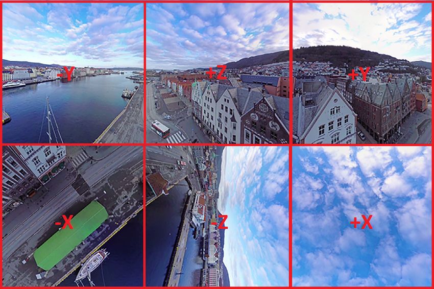
(a) Equirectangular mapping (b) Cube mapping
Figure 2.3: (a) An Equirectangular projection mapping. (b) A Cube projec-
tion mapping in 3x2 layout with the directional axis overlayed. Some faces
are rotated according to JVET recommendations. Image adapted from [26].
this may depend on the system. The axis system also represents the differ-
ent viewing directions, with +z being ”forward”, -z being ”backwards”, +y
being ”right”, -y being ”left”, +x being ”up” and -x being ”down”. Each
axis has a range of [0◦ , 360◦ ). When receiving the positional information
from the client, the rendering device updates the cameras that represent the
head/eyes of the user in the virtual world to match the user’s position and
orientation.
The question of what projection mapping is best for VR streaming (in
order to map a sphere to a rectangular surface) is an area of active and on-
going research. At the moment, there is no answer as to what method is
best: different authors have invented different methods and each work well
in a particular way. However, there are some common methods that are of-
ten used nowadays: Equirectangular and Cubemap projection mappings are
the most common (see Figure 2.3). In equirectangular projection the ver-
tical direction of the surface corresponds to the latitude of the sphere, and
the horizontal direction corresponds to the longitude. Cubemap projection
works by assuming a cube circumscribes the sphere, and each point on the
sphere is then mapped to the corresponding point on the cube face behind
the sphere point. The cubemap projection is natively supported by graphics
libraries such as OpenGL, and is thus commonly used in VR games and other
computer-generated imagery. Cubemap projection also does not suffer from
shape distortion and has less redundant pixels compared to Equirectangu-
lar projection [26]. Figure 2.3(a) shows an example of an Equirectangular
mapping and Figure 2.3(b) shows an example of the cube mapping. The lay-
out in Figure 2.3(b) is the recommended layout by the Joint Video Experts
Team (JVET), however a 4x3 layout is also commonly used. Many moreCHAPTER 2. BACKGROUND 19
projection methods exist nowadays. For example: Facebook uses a pyramid
shape mapping for their 360◦ video streaming, which devotes more pixels to
the viewport. For an excellent discussion of different projection methods, see
[26].
2.4 Related work: 360◦ Video Streaming
In streaming VR video, one of the main concerns is how to limit bandwidth
consumption while maintaining high video quality. Since a user is only view-
ing a portion of the video at a given time, we can exploit that to provide
higher quality in the viewport region while limiting the quality of the pe-
ripheral regions. This idea is the core of all current work on optimizing
VR video bandwidth consumption, but it requires careful fine-tuning of the
used algorithm to make sure quality changes are transparent to the user
and the quality level changes accordingly when a user changes their gaze.
In [16], the authors develop a viewport-adaptive system for streaming 360◦
video that prepares multiple representations of Quality Emphasis Centres
(QEC’s). These representations differ in quality level and bitrate to be able
to use higher quality/bitrate video for the viewport and lower for the pe-
ripheral area. The video is cut into segments with different QEC locations
and for different quality levels. The client then chooses the QEC closest
to the gaze location and the quality level befitting its available bandwidth.
Their system is somewhat related to ours in that they use an adaptive al-
gorithm to determine when to switch to a different QEC or different quality
level. However, their solutions relies on many pre-encoded segments that are
stored on a server, which makes it impossible to use this method in real-
time streaming systems. Furthermore, their algorithm was trained using a
dataset of head movements. The Jaunt Inc. dataset is widely used, but it
is generated from users watching 360◦ video which may comprise very differ-
ent head movement behaviour compared to Interactive VR, or even different
videos. In a follow up paper, [21] augmented the system to include a model of
the optimal Quality Emphasis Region quality level distribution. This model
was again generated from head traces of users watching a 360◦ video. In a
simplified experiment, they reported up to 45% bandwidth savings, given 4
quality-variable video versions and perfect head movement prediction.
The work of [16], [21] nicely illustrates the main strategies for bandwidth
savings in 360◦ video at the moment: cut a video up into pieces, use some
algorithm to match these pieces to the user’s viewport, and have multiple
quality versions available of each piece to dynamically adjust the quality
of different regions. For example, [19] analyzed a different dataset of overCHAPTER 2. BACKGROUND 20
1300 head traces to determine common gaze locations. They then propose
a multicast DASH-based solution that streams a higher quality tile based
on the likelihood of that tile being in the viewport. Similarly, [23] used
these strategies to optimize bandwidth consumption, focusing explicitly on
the DASH streaming algorithm and modern encoders such as H.265 and
VP9. In [28] the authors realize the multitude of different optimizations for
streaming 360◦ video are becoming increasingly hard to compare due to the
lack of standardized tests, and propose a tool to compare their effect on QoE
for different optimizations, viewports, encoding and streaming algorithms. In
the context of using head trace datasets for determining the most important
regions in a VR video, several datasets have been developed. Apart from
the ones just mentioned, see also for example [25], [34]. Gaze and saliency
analysis may provide us with more useful information of how people control
there gaze in a spherical video. For some examples, see [31], [33], [34].
2.5 Related work: Real-time Interactive VR
Streaming
The 360◦ video streaming solutions we discussed above rely on some form of
offline representation of the video, usually in the form of multiple tiles with
multiple quality representations. Not only does this require more storage
space on the server side, but it also cannot be applied to fully live, on-demand
streaming of VR content. In this section we discuss some of the works that
are designed to optimize live VR streaming, such as live streaming of 360◦
video and streaming of Interactive VR, such as cloud VR gaming.
In [14] the authors developed a system to predict head movements and,
based on the predicted head movement, transmit only the part that corre-
sponds to the predicted viewport location. Using a machine learning algo-
rithm trained on a dataset collected from users watching 360◦ videos, they
were able to accurately predict the new viewpoint on a timescale of 100-
500ms. They transmit a circular area for the predicted new viewpoint with
a buffer circular area around it sized based on how confident the algorithm
is. The authors report a 0.1% failure ratio and up to 45% bandwidth sav-
ings. Their results are promising, but based on 360◦ videos and they do not
mention how the partial rendering was implemented. This work is in a way
similar to ours, as they exploit the fact that users are only viewing a portion
of the VR sphere at a time and stream only that part including a buffer
area. They do note that a circular area may not be ideal in terms of band-
width savings, and do not compare their solution to other head movementCHAPTER 2. BACKGROUND 21
predictions algorithms.
In [32] an untethered VR streaming system is proposed that supports up
to 4K resolution with a latency of 20ms. The system consists of multiple en-
coders and decoders working in parallel, supported by a 60Ghz wireless link.
They analyse the component latency of the system and particularly develop
a V-Sync driven version of the system to overcome the latency introduced by
missing V-Sync calls. Their work serves as an inspiration for the technical
implementation of a VR streaming system and is one of the few that actively
tackles the issue of latency in VR streaming and the high FPS requirement.
It should be noted, however, that they point out that their system used a
60Ghz wireless link which is not commonly available and limits the mobility
of the user. Furthermore, they used a laptop for receiving and decoding the
video. Although they do not specify the model, the average laptop computer
is much more powerful than a smartphone, which is used in this work.
FURION is a system designed by [35] to support Interactive VR streaming
to mobile devices. By offloading part of the rendering (background) to a
remote server and using the mobile device for foreground rendering and in-
teraction, they manage to achieve a 14, 1 and 12ms latency to controller,
rotation and movement interaction respectively. Their system is designed
with the same type of mobile device in mind as our work: smartphones such
as the Google Pixel or Samsung Galaxy S series combined with household
connectivity such as 802.11ac Wi-Fi. Furthermore, it is developed based on
Unity3D and Google Daydream and can be relatively easily added to exist-
ing content as a plugin. Unlike our VR streaming system, they pre-fetch the
entire view for close-by gridpoints, whereas our work and [32] render just
the required view on-demand. A key difference between [35] and our work
presented here on dynamically rendering and streaming a VRE is that they
do not employ any viewport-aware rendering strategies such as ours and thus
do not have to consider head movement and latency compensation.
In [36] the authors present a VR streaming system that dynamically
adapts a buffer area to compensate for system latencies. Their idea is similar
to ours, although they use different methods and posit that it is not necessary
to explicitly compensate for head movements. Further similar to our work is
their assumption of some VR streaming system either in the cloud or in a Mo-
bile Edge Cloud that streams content to a thin client. The authors present an
extensive latency analysis in their work, and show that their adaptive margin
area calculations are based on a similar rolling average RTT approach. How-
ever, it is unclear how the authors compensate for different head movements.
Currently their calculations are based on a head movement dataset and they
evaluate their system’s performance by streaming 360◦ video. Compared to
their work we explicitly focus on live user head movements and emphasize theCHAPTER 2. BACKGROUND 22
need for reliable head orientation prediction. Furthermore our work focuses
on Interactive VR streaming such as gaming, and while [36] supports this in
theory, it is not discussed any further in their work. Due to their focus on
LTE networks and promising results, combined with our results presented in
this work, it seems that this approach of adaptively rendering the user FoV
while compensating for network conditions and system latency is a promising
way of enabling Interactive VR streaming with high QoE.
Our work is in part based on the work done by [30], who developed
CloudVR, an Interactive VR system designed to enable VR streaming using
cloud-based server instances that stream to thin clients. In particular, the
prototype VR streaming system used in this work is based on the prototype
system in [30]. Lastly, Flashback [15] and MoVR [18] further present VR
streaming systems that aim to provide high-quality untethered Interactive
VR experiences.Chapter 3
System Architecture
In this chapter we will describe the VR streaming system that is used in the
current work. Although the system itself, it’s development or optimization
are not the focus of this work, it will be beneficial to know a VR streaming
system works in general. The key part of this work, our solution to the prob-
lem stated in Chapter 1, is described in Chapter 4. A working prototype of
the VR streaming system described here has been developed in the CloudXR
project and is largely based on the CloudVR system presented in [30]. It is
within this prototype that we have applied our Dynamic Viewport-Adaptive
Rendering solution.
Our Virtual Reality streaming system (henceforth referred to as ”Sys-
tem”) is implemented as a plugin for a game engine that acts as the server and
an application for a mobile client. The server plugin (henceforth ”Server”)
can be implemented during application development in game engines such
as Unity3D and Unreal Engine. The client app (henceforth ”Client”) is a
standalone application that connects to a compatible server and renders the
video received from the server on the client display while sending user data to
the server. The System was designed with cloudification in mind: the plugin
can easily be integrated into existing and new projects and facilitates run-
ning the entire application in a cloud environment. Furthermore, the system
was designed primarily with mobile clients in mind: efficient software and
fast hardware on the server side minimize the system latency and require less
bandwidth, crucial for streaming to a low-power mobile device. The System
utilizes a novel partial cubemap layout to emphasize the quality of the front
face of the VR video sphere, while the front face is always kept in the user’s
viewport. This means that we can dynamically change what part of the VRE
to render based on where the user is looking, without to need to render the
full 360◦ FoV at all times.
23CHAPTER 3. SYSTEM ARCHITECTURE 24
Figure 3.1: Diagram of a typical processing loop in the VR streaming system.
Our solution is provided as plugins (green boxes) to an existing game engine.
The blue boxes represent data being transmitted over a network connection.
The client plugin retrieves data from the client device (left side) through an
API such as Google Daydream (not pictured).
3.1 Server
On the server side, a typical render cycle1 (for one video frame) looks like
this:
1. Receive orientation, position and control data from the client
device. Depending on the implementation this data may have been
received earlier or slightly later: in any case the server uses the most
recent data to render the new frame when the render cycle is started.
The Server sets the cameras to the received orientation and position,
so that the VRE on the server matches the user orientation and virtual
position on the client. The control data is then used to advance the
game logic and update the world state according to the application
specifics. Control data includes, but is not limited to: button presses,
1
By render cycle we mean one full iteration in the game engine logic that updates the
world state and renders the virtual world to an output, including encoding. Typically one
such iteration is done for each video frame.CHAPTER 3. SYSTEM ARCHITECTURE 25
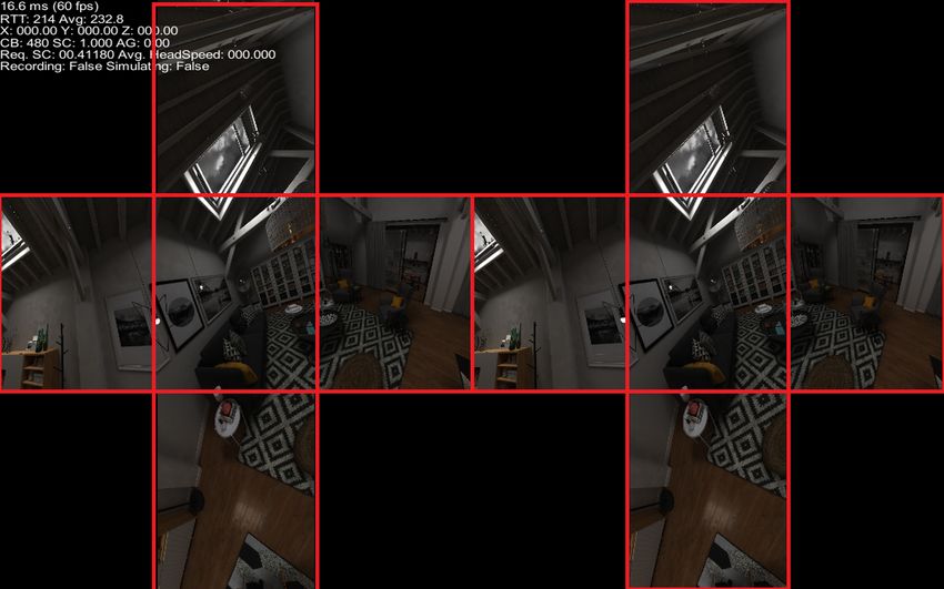
Figure 3.2: The 3x3 cubemap layout used in our system with left and right
eye content. The middle rectangle for each eye is the front face of the cube
(+z). In this particular example we are rendering all of the peripheral area
except for the back face (-z). The cube faces may look slightly distorted in
the figure due to rendering the output to a desktop monitor, but in practice
each face is square and of equal size.
controller orientation and position, local game object parameters, video
frame and system parameters.
2. Render the virtual scene, using the cameras, to a temporary
texture. The System uses 5 cameras per eye to render the virtual
world to the output texture. Each camera has a 90◦ field of view, and
each camera is aligned to a directional axis. Combining the output of
all cameras (typically 6), would give us the 360◦ FoV required. In this
case, however, we render using only 5 cameras, ignoring the -z (rear)
direction providing a 270◦ × 180◦ FoV.
3. Combine the camera textures into a single rectangular tex-
ture for encoding. The System utilizes a partial cubemap projection
method to combine the camera textures into a single texture. In this
case, we render the +x and -x, +y and -y and +z axis (vertical, hori-
zontal and frontal views), but not the -z direction (rear direction). ThisCHAPTER 3. SYSTEM ARCHITECTURE 26
has a number of benefits: for one, it lowers the amount of rendering
needed to compile a full video frame. Second, it allows us to use a 3x3
layout for the partial cubemap, where the front face (+z) is in the mid-
dle, adorned by the horizontal (y) and vertical (x) direction faces (See
Figure 3.2). This will be crucially important for dynamically scaling
the faces to devote more space to the front face in the video texture,
which is discussed in Chapter 4.
4. Encode the texture into a video frame. The video texture is
essentially no different than from what would be rendered on screen
in a normal game, or displayed on a tethered HMD. However, because
of it’s large size and the need for streaming it to a client, we need to
encode it. The Server uses the FBCapture SDK [40] to capture the
rendered texture, and pass is to a hardware-accelerated encoder. In
the meantime, the Server can start with it’s next render cycle.
5. Stream the video frame to the client, together with control
data. The resulting encoded video frame can then be passed to the
network stack and sent to the client. The control data includes, but
is not limited to: the orientation that the video frame is based on, as
well as video parameters. We use a TCP socket connection to ensure
the correct order of the frames being delivered.
3.2 Client
The client application utilizes the HMD manufacturer’s SDK (e.g. Google
Daydream, Oculus Quest) to display a received video frame on the device’s
display, in such a way to match the layout and properties of the headset’s
lenses. Furthermore, the SDK provides API access to the different XR prop-
erties of the nodes, such as the head orientation, eye position, controller
position, etc., and matches the real-world orientation to the corresponding
VRE orientation, so that the user can look and move around in the VRE by
physically moving. Optionally, the Client can locally render some game ob-
jects and perform part of the game logic locally. The current System utilizes
such a hybrid approach, where the controller for example is displayed in the
VRE using local rendering [30]. The Client consists of a standalone appli-
cation (in this case based on Unity3D) and our own native Android decoder
plugin. A typical render cycle looks like this:
1. Receive a video frame and control data from the server. The
decoder plugin is multi-threaded and takes care of receiving NAL unitsCHAPTER 3. SYSTEM ARCHITECTURE 27
and control data from the server. The received NALU’s and control
data are fed to a buffer for processing. The network connection is based
on a TCP/IP socket to ensure correct order of both control data and
video frames.
2. Decode the received video frame. The decoder is based on Google
Android’s MediaCodec API. It works asynchronously by waiting for a
decoder inputbuffer to become available and then feeding it the next
NAL unit. When the buffer is processed the output is rendered to an
internal texture that can be accessed by the higher-level Client appli-
cation.
3. Process the game logic and update the world state. In case
of local rendering and interaction events, the world state is updated
accordingly. Furthermore, the new control data (e.g. user orientation,
frame ID, performance metrics) are prepared.
4. Update the shader parameters and render the video frame to
the display. The client displays a spherical video by projecting the re-
ceived imagery to the virtual environment’s skybox. A modified shader
provides support for stereoscopic panoramic rendering to the skybox.
In order to be able to modify the content outside of the user’s viewport
without the user noticing, the skybox is oriented along the orientation
of the video frame which is extracted from the received control data.
This means that a user is always facing the front face (+z direction)
of the cubemap/sphere. The received video frame is in rectangular
format comprising a non-spherical layout of the faces. The cubemap
faces in the video frame are moved to a separate texture for each eye in
the common 4x3 cubemap layout, which the shader natively supports.
With the shader being updated to the new orientation and having ref-
erences to the rearranged input textures, the content is rendered to the
Client device’s display. The HMD’s SDK provides the warping of the
image to match the lens parameters.
5. Send the current player control data to the server. The client
sends the server the control data needed to render the next frame. Note
that this step does not necessarily happen at the end of the render cycle.Chapter 4
Dynamic Viewport-Adaptive
Rendering (DVAR)
Normally when streaming a VR video frame, each viewing direction is repre-
sented by the same amount of pixels. In case of streaming a cubemap layout,
each face has an equal amount of pixels, and the six faces together offer 360◦
of visual content. Notwithstanding technologies that alter the resolution of
the video frame, such as adaptive resolution used in video streaming, the size
in pixels of a video frame is fixed at a given time. This means that all cube
faces are proportionally the same size. However, a user is only looking in one
direction at a time, with a limited FoV (generally between 90◦ − 110◦ ). As
we discovered in the Background section, most companies and researchers
have discovered this as well and use it to non-uniformly assign better quality
factors to the part of the scene the user is looking at (the viewport). This has
been done using frame tiling for example, where tiles in the viewport area
of a video frame are given higher quality than the surrounding areas. Many
more solutions exist, of course, but the consensus seems to be that streaming
all areas of a VR video frame in equal quality is a waste of valuable resources.
In this work we mostly deal with square cube faces and square video
frames for a given eye. This means that the height and width of an area will
be equal. Because of this we employ a shorthand notation unless otherwise
noted: an area with a resolution of 2048x2048 pixels (for example) will be
referred to as an area of 2048 pixels.
4.1 Idea
Given a streaming system with a low enough latency, and given that we can
orient the frontal direction with the users viewing direction, we can assume
28CHAPTER 4. DYNAMIC VIEWPORT-ADAPTIVERENDERING (DVAR)29
(a) Original (b) Increased cube face size (c) Resulting video frame
Figure 4.1: Transforming a 3x3 cubemap layout to proportionally increase
the size of the front face (+z). In (a) the original proportions are displayed
with their axis directions. Each cube face is rendered 100%. The blue border
represents the video frame boundaries for one eye. In (b) we have increased
the size of all faces, such that the side faces do not fit into the video frame
anymore. The video frame size remains the same. In (c), we have adapted
the amount of side face to render, such that all faces fit into the video frame,
resulting in a proportionally larger area for the front face.
that a user will only be viewing the frontal direction for the majority of
the time and any changes in orientation are quickly compensated for in the
next video frame. This assumption allows us to ignore the rear direction
of the content sphere, because by the time the user will have reached that
orientation, a new video frame will have already placed the frontal direction
in the way of the previously rear direction. This then, allows us to use
the partial cubemap layout described earlier, in which we only utilize 5 front
faces of a cubemap and ignore the back face. Our contribution is utilizing this
layout to proportionally enlarge the frontal cube face while rendering only
part of the side faces (top, bottom, left, right) in their respective direction.
This way we end up with a video frame that offers proportionally more pixels
to the front face.
For an example, see Figure 4.1: (a) represents the normal layout, with
each cubemap face having an equal proportion and equal amount of pixels.
Because we disregard the back face, we only need to place the other 5 faces
on the video frame in a plus-shape layout (3x3). This square video frame
represents one eye, and the other eye is generated correspondingly. Now, we
can devote more pixels to the front face by enlarging all cubemap faces to
have a desired resolution. However, given that the video frame resolution
stays the same, parts of the side faces will now not fit within the frame andCHAPTER 4. DYNAMIC VIEWPORT-ADAPTIVERENDERING (DVAR)30
need to either be compressed or cropped as in (b). Instead, our solution is
to simply only render the part of each side face that fits within the video
frame given the larger front face. We end up with the video frame as in (c),
where the front face now contains 23 of the pixels, and we only render 61 of
each side face. The resulting video frame offers more pixels in the front face,
but limits the available field-of-view in the VRE since only part of the left,
right, top and bottom faces are rendered. The non-rendered areas, including
the back face, simply appear as black pixels. We can arbitrarily choose the
amount of pixels (i.e. the proportion) for the front face by adjusting the
amount of side face to render, but there are some caveats related to the
user’s head movement: when the user moves his head and the new frame
(with the ”recentered” front face) takes too long to be displayed, the user
will see the unrendered area. This is obviously highly detrimental for the
user’s Quality of Experience, so in the next section we will discuss how to
prevent this.
First, however, we’ll have a look at how this is implemented in prac-
tice, so as to gain a better understanding of the exact workings. Combined
with the optimization process described in Section 4.3, we have dubbed this
method of rendering DVAR, for Dynamic Viewport-Aware Rendering. The
optimizations below will allow us to dynamically adjust the amount of side
face to render, based on the current system parameters such as latency, so
as to maximize the front face resolution while maintaining good QoE. This
method is viewport-adaptive in that we rotate the cube/sphere’s front face to
the user’s viewport every time and because we devote a maximum amount of
pixels to the viewport given the system and optimization constraints. Lastly,
we do not simple crop or cut the remainder of the side faces that do not fit
on the video frame, but rather do not render those areas at all on the Server.
Thus DVAR also positively affects rendering times and avoids unnecessarily
using resources.
4.2 Implementation
On the server side, the Server plugin has a module that calculates the desired
amount of side face to render at every render cycle. From here on out we
will refer to the amount of side face to render as the side face percentage
(SF %), and the front face resolution and proportional size automatically
follow from the side face percentage: if we render 10% side face, and have
a face on each side of the front face, the front face occupies 80% of the
video frame. In case of a 2048x2048 pixel video frame for one eye, this
amounts to 1638x1638 pixels for the front face, 1638x204 pixels for the topYou can also read