Urban Rail integration into ITS-G5 - CAR 2 CAR Communication Consortium - CAR 2 CAR Communication ...
←
→
Page content transcription
If your browser does not render page correctly, please read the page content below
CAR 2 CAR Communication Consortium

                  Urban Rail integration into ITS-G5
                   CAR 2 CAR Communication Consortium

About the C2C-CC
Enhancing road safety and traffic efficiency by means of Cooperative Intelligent Transport
Systems and Services (C-ITS) is the dedicated goal of the CAR 2 CAR Communication
Consortium. The industrial driven, non-commercial association was founded in 2002 by vehicle
manufacturers affiliated with the idea of cooperative road traffic based on Vehicle-to-Vehicle
Communications (V2V) and supported by Vehicle-to-Infrastructure Communications (V2I).
Today, the Consortium comprises 88 members, with 18 vehicle manufacturers, 39 equipment
suppliers and 31 research organisations.
Over the years, the CAR 2 CAR Communication Consortium has evolved to be one of the key
players in preparing the initial deployment of C-ITS in Europe and the subsequent innovation
phases. CAR 2 CAR members focus on wireless V2V communication applications based on
ITS-G5 and concentrate all efforts on creating standards to ensure the interoperability of
cooperative systems, spanning all vehicle classes across borders and brands. As a key
contributor, the CAR 2 CAR Communication Consortium works in close cooperation with the
European and international standardisation organisations such as ETSI and CEN.

Disclaimer
The present document has been developed within the CAR 2 CAR Communication Consortium and might be further
elaborated within the CAR 2 CAR Communication Consortium. The CAR 2 CAR Communication Consortium and its
members accept no liability for any use of this document and other documents from the CAR 2 CAR Communication
Consortium for implementation. CAR 2 CAR Communication Consortium documents should be obtained directly from
the CAR 2 CAR Communication Consortium.
Copyright Notification: No part may be reproduced except as authorized by written permission. The copyright and the
foregoing restriction extend to reproduction in all media. © 2019, CAR 2 CAR Communication Consortium.

C2CCC_TR_2053_Urban_Rail.doc                       28/01/2019                                        Page 1 of 69
CAR 2 CAR Communication Consortium

Document information

Number: TR 2053                   Version:     1.0.0             Date:          2019 – 01 – 11

Title:        Urban Rail integration into ITS-G5                 Document       Report
                                                                 Type:

Release: 28 January 2019

Release       Released for publishing
Status:

Status:       Completed

 Author:

 Company
                      Author                                              Chapter
 /Institute

 FBConsluting Sarl    Friedbert Berens
 Commsignia           András Edelmayer, András Váradi
 Netellany            Michelle Wetterwald

 Approval:

 Function            Name, Company                        Date           Signature

 Outstanding Issues

 Issue                                                      Author        Chapter

C2CCC_TR_2053_Urban_Rail.doc                 28/01/2019                              Page 2 of 69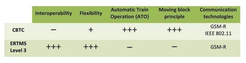
CAR 2 CAR Communication Consortium

Changes since last version

 Title:

 Explanatory
 notes:

 Issue    Rev.   Date   Changes                Edited by   Approved

C2CCC_TR_2053_Urban_Rail.doc      28/01/2019                  Page 3 of 69
CAR 2 CAR Communication Consortium

Content
About the C2C-CC ..................................................................................................................... 1
Disclaimer .................................................................................................................................. 1
Document information ................................................................................................................ 2
Changes since last version ......................................................................................................... 3
Content ...................................................................................................................................... 4
List of figures .............................................................................................................................. 5
List of tables ............................................................................................................................... 6
1     Introduction ......................................................................................................................... 7
    1.1    Abstract ........................................................................................................................ 7
    1.2    Survey of document ..................................................................................................... 7
2     Technical overview of railway communication systems ....................................................... 8
    2.1   Introduction .................................................................................................................. 8
    2.2   Inter-train communication systems ............................................................................... 8
    2.3   Automatic Train Operations (ATO) networks ................................................................ 9
    2.4   Communications Based Train Control (CBTC) ............................................................. 9
       2.4.1        CBTC architecture .............................................................................................................. 11
       2.4.2        The moving block principle ................................................................................................. 11
       2.4.3        CBTC Characteristic #1 ...................................................................................................... 12
       2.4.4        CBTC Characteristic #2 ...................................................................................................... 12
       2.4.5        CBTC Characteristic #3 ...................................................................................................... 13
    2.5      European Railway Traffic Management Systems (ERTMS)........................................ 14
    2.6      GSM-R communication .............................................................................................. 15
    2.7      CBTC vs ERTMS ....................................................................................................... 16
3     Urban Rail communication systems .................................................................................. 18
    3.1   CBTC/ERTMS status ................................................................................................. 18
    3.2   Basic CBTC communication requirements ................................................................. 18
    3.3   Messages in safety related CBTC (Urban Rail) systems and their requirements ........ 19
    3.4   Spectrum requirements for a CBTC system ............................................................... 23
4     Regulation in the 5.9 GHz band......................................................................................... 26
    4.1  Existing status ............................................................................................................ 26
    4.2  Proposed changes ..................................................................................................... 27
5     Integration of Urban Rail and Rail systems in C-ITS and ITS-G5....................................... 30
    5.1    Main concept overview ............................................................................................... 30
       5.1.1        Option 1: Connection-based solution ................................................................................. 30
       5.1.2        Option 2: Broadcast-based solution ................................................................................... 31
    5.2      Description of Option 1: Connection-based solution ................................................... 31
    5.3      Description of Option 2: Broadcast-based solution ..................................................... 31
       5.3.1        ITS-G5: Nomenclature and main properties ....................................................................... 32
       5.3.2        ITS-G5 communications architecture and protocol stack ................................................... 33
       5.3.3        Requirements and solutions for V2X safety and security ................................................... 34
       5.3.4        Safety and security of CBTC communications ................................................................... 35
       5.3.5        Preliminary considerations to the use of broadcast mode ................................................. 36
    5.4      Positioning and timing ................................................................................................ 37
    5.5      Message set proposal ................................................................................................ 38
       5.5.1        UR-CAM ............................................................................................................................. 39
       5.5.2        UR-DENM ........................................................................................................................... 40

C2CCC_TR_2053_Urban_Rail.doc                                        28/01/2019                                                          Page 4 of 69
CAR 2 CAR Communication Consortium
5.5.3 UR-SPAT ............................................................................................................................ 40
5.5.4 UR-MAP .............................................................................................................................. 40
5.6 Overall architecture and protocol extensions required ................................................ 41
6 IEEE 802.11 for ITS and CBTC use - Roaming frequency and latency.............................. 42
7 Conclusions and further steps ........................................................................................... 44
8 Appendix A - Proposal for Urban Rail Protected Zones ..................................................... 45
8.1 Overview .................................................................................................................... 45
8.2 Requirements ............................................................................................................. 45
8.3 Beacon based on Cooperative Awareness Messages (CAM) ..................................... 46
8.3.1 Introduction ......................................................................................................................... 46
8.3.2 Summary of the CEN DSRC zones protection ................................................................... 46
8.3.3 Proposal of potential updates to address the protection of UR-Access Points .................. 48
8.4 Conclusions ............................................................................................................... 49
8.5 Additional information: Data elements for protected zone definition [AD-3]................. 50
9 Appendix B - Geographically-Scoped Multicast ................................................................. 53
10 Appendix C - CBTC 5.9 GHz projects list .......................................................................... 56
10.1 CBTC deployed or in construction .............................................................................. 56
10.2 CBTC new projects .................................................................................................... 58
11 Appendix D - Spectrum requirements calculation .............................................................. 60
12 Appendix E – Comments received from a national Frequency regulator on option 2 ......... 65
13 Appendix F – References .................................................................................................. 66
13.1 List of abbreviations ................................................................................................... 66
13.2 Applicable documents ................................................................................................ 68
13.3 Related documents .................................................................................................... 69
List of figures
Figure 2-1: Simple zone control with partially overlapped zones ............................................... 11
Figure 2-2: Zone control with line crossing and three zone controllers and multiple overlapped
zones ....................................................................................................................................... 11
Figure 2-3: Location determination of trains by means of traditional CBTC technology ............ 12
Figure 2-4: Traditional CBTC communications function blocks ................................................. 13
Figure 2-5: EU Decision on SRD devices in 874-876 MHz / 915 – 921 MHz [RD-1] ................. 16
Figure 4-1: European road ITS frequency allocation scheme [see AD-5] .................................. 27
Figure 4-2: European road ITS channel allocation scheme ...................................................... 27
Figure 4-3: JTFIR proposal for prioritisation mechanism [AD-10].............................................. 28
Figure 5-1: Road ITS station reference architecture in acc. with [AD-7] .................................... 33
Figure 5-2: General overview of the European road ITS security credential system ................. 35
Figure 5-3: ITS Station model showing UR-ITS specific component in Facilities layer .............. 39
Figure 8-1: Basic structure of a CAM message ........................................................................ 47
Figure 8-2: Example CAM Protected Zone represented as an ellipse ....................................... 49
C2CCC_TR_2053_Urban_Rail.doc 28/01/2019 Page 5 of 69CAR 2 CAR Communication Consortium Figure 9-1: Examples of scenarios for Geographically-Scoped Multicast (GMC) messaging .... 53 Figure 9-2: Geographically-Scoped Multicast (GMC) messaging .............................................. 54 List of tables Table 2-1: CBTC and ERTMS system similarities and differences ........................................... 17 Table 3-1: List of messages used in the CBTC system............................................................. 20 Table 3-2: CBTC Application services Uplink and Downlink Throughput requirements communication with one ZC ..................................................................................................... 21 Table 3-3: CBTC Application services Uplink and Downlink Throughput requirements communication with three ZC ................................................................................................... 22 Table 3-4: CBTC Application services Uplink and Downlink Throughput requirements communication with three ZC and one PSD ............................................................................. 22 Table 3-5: Average and maximum spectrum requirements calculation for Location report three ZC ............................................................................................................................................ 24 Table 3-6: Average and maximum spectrum requirements for all messages in Urban Rail CBTC systems .................................................................................................................................... 24 Table 8-1: Structure of the CAM with Protected Zone elements ............................................... 47 Table 10-1: CBTC lines already deployed or under construction .............................................. 58 Table 10-2: CBTC new projects................................................................................................ 59 Table 11-1: Average and maximum spectrum requirements calculation for Location report three ZC ............................................................................................................................................ 60 Table 11-2: Average and maximum spectrum requirements calculation for Periodic Train Functional Status messages .................................................................................................... 61 Table 11-3: Average and maximum spectrum requirements calculation for on demand specific status message ........................................................................................................................ 61 Table 11-4: Average and maximum spectrum requirements calculation for Movement of authority DL 3 ZC.................................................................................................................................... 62 Table 11-5: Average and maximum spectrum requirements calculation for Information about line from ZC .................................................................................................................................... 62 Table 11-6: Average and maximum spectrum requirements calculation for Request for health train status ....................................................................................................................................... 63 Table 11-7: Average and maximum spectrum requirements calculation for Burst traffic data base update ...................................................................................................................................... 64 Table 11-8: Average and maximum spectrum requirements calculation for Request for health train status ....................................................................................................................................... 64 C2CCC_TR_2053_Urban_Rail.doc 28/01/2019 Page 6 of 69
CAR 2 CAR Communication Consortium

1 Introduction

1.1 Abstract
In recent years the Urban Rail community has proposed and pushed to use the spectrum
allocated to the road ITS systems in the band 5.9 GHz for the use of their systems, mainly metro
systems in big cities. The deployed communication systems do not follow any harmonized
specification and are based on a set of requirements. The used systems are proprietary and
mainly based on 802.11a and a DSSS spread spectrum system. A sharing between these
systems and the existing ETSI Road ITS systems can only be reached by complex mitigation and
sharing techniques. C2C-CC has proposed to deploy an extended road ITS systems based on
the ETSI ITS specifications for the use in Urban Rail. This integrated approach would significantly
simplify the sharing operation and could reduce the cost of Urban Rail systems due to the reuse
of an existing system.
This report is intended to give an initial evaluation of the required changes and extensions in the
ETSI ITS set of standards and specifications in order to support the deployment of this
communication standard in the field of rail and urban rail. It can be used as the basis for further
development and standardization work in the field of rail communication with the main focus on
Urban Rail systems.

1.2 Survey of document
The use and integration of wireless communications to provide railway operators with a means to
control and manage the train traffic on their networks is a must to make the train traffic safe and
sustainable in the future. In this report, we survey the train communications technologies recently
used or under development mentioning the related harmonization and standardization activities.
The relation with Cooperative Intelligent Transportation Systems (C-ITS) communications and the
possible joint development of the two different, though highly interdependent modes of
transportation, is shortly characterized.
In this report we first summarize the basic railway communication solutions which are used
already in the practice in urban and also in long-haul line solutions. Then, the Day 1 C-ITS
communication solutions are briefly characterized and the idea of the shared use of C-ITS
technology between road and rail users is presented in accordance with the recent developments
of the standardization activities.

C2CCC_TR_2053_Urban_Rail.doc                28/01/2019                                Page 7 of 69
CAR 2 CAR Communication Consortium

2 Technical overview of railway communication systems

2.1 Introduction
The primary objective of the application of railway communication systems is to provide railway
operators with a means to control and manage the train traffic on their networks.
Railway communication systems are varied and can be classified in different application groups,
such as safety and control oriented, operator and customer-oriented services and networks. By
architecture one can distinguish on-board and inter-vehicle communications. On-board
communication networks were installed aboard trains since the end of the 1980s to reduce the
cable beams used to transfer information between different devices like human to machine
interface (HMI), passenger information system (PSI), or heating, ventilating, and air conditioning
systems etc., following the general technology trends of drive-by-wire systems commonly used in
aerospace and car industries. This technology is out of the scope of our recent technology review
and will not be treated any further.
As to inter-train communication, there is a well-defined technology separation between systems
that are being used in Mass transit networks (or urban lines in general) and the ones being used
for Mainline (or long-haul lines). Mass transit and Mainline communication systems evolved along
two separate trajectories resulting in the situation in which the two ecosystem approaches coexist
in some networks. Moreover, each of these systems has the necessary maturity to step forward
to an integrated solution that comprises the best of both worlds. They are the Communications-
Based Train Control (CBTC) system and European Rail Traffic Management System (ERTMS).
In the following sections we characterize the two distinct technology approaches in a historical
perspective.

2.2 Inter-train communication systems
There was the ultimate need to provide railway operators with a means to control and manage
the train traffic on their own networks. Obviously, this requirement necessitates the continuous
availability of a seamless communication connection between rail vehicles and the control
infrastructure. The vehicle to infrastructure communication was deployed for train applications in
the past decade. The deployment focus was studiously Train-to-Ground (T2G) communication.
Train-to-Train (T2T) communication was not in the foreground until recently.
Rail traffic is characterized by poor braking capabilities of trains and rail vehicles in general, the
fixed path, and the inability to avoid obstacles. Maintaining a short following distance between
trains and ensuring safe braking distances between rail vehicles on busy commuting lines
necessitate the use of safety-related, time-critical train control applications, which are enabling
technology parts of the Automatic Train Operations (ATO) networks. Because of the safety
requirements, they impose stringent reliability and availability requirements on the radio
communication technology used.
T2G connectivity solutions are basically using GSM, IEEE 802.11 and other proprietary
technologies and solutions. While GSM-R (GSM for railways) is built on the GSM network
infrastructure, the 802.11 microwave (WiFi) solutions make use of the private network of wayside
units. Both technologies ensure connectivity of the trains with the control centre in order to send
and receive control information. Various application-oriented control networks were defined over
those wireless access technologies in the past decades. These are summarised in the following
sections.

C2CCC_TR_2053_Urban_Rail.doc                 28/01/2019                                  Page 8 of 69
CAR 2 CAR Communication Consortium

2.3 Automatic Train Operations (ATO) networks
The basic objective of a railway control system is to prevent trains from colliding with each other
and with obstacles and prevent derailing based on various train detection technologies. The
detection system combined with a signalling and a communication system makes up the
traditional Automated Train Operations (ATO) technology. In communication-based railway
signalling, different means of telecommunication are used to transfer train control information
between the train and the wayside.
ATO systems still rely on the T2G link to send and receive control signals and monitor train
conditions from a central management site. As train operations move towards increasingly
automated and even autonomous, Automated (or Unattended) Train Operations (ATO/UTO)
solutions perform the following basic functions and are implemented through the interaction with
control centres in the rail infrastructure.
   •   In the first approach, traditional Automatic Train Stop (ATS) systems represent the
       classical safety train control applications which helped to ensure the adherence of
       requested clearing distances between trains. ATSs were integrated in the rail operation
       and acted as the interface between the operator and the system, managing the traffic.
       Other tasks include the event and alarm management as well as acting as the interface
       with external systems.
   •   Automatic Train Control (ATC) or Automatic Train Protection (ATP) is a general class
       of train protection system for railways that, beyond ATS requirements, involves a speed
       control mechanism in response to external inputs. The objective of this comprehensive
       ATC/ATP system solution is to constantly monitor the train speed and compare it to the
       maximum values that are sent by trackside signalling systems. ATC/ATP is probably the
       most critical CBTC subsystem, which helps prevent collisions as a result of the driver’s
       failure to observe a signal or speed restriction.

2.4 Communications Based Train Control (CBTC)
Communications-Based Train Control (CBTC) is an advanced ATO system using bidirectional
T2G communications to ensure the safe operation of trains and rail vehicles. It is a continuous,
automatic train control system utilizing train location determination and continuous, bidirectional
train-to-wayside data communications. Train-borne and wayside processors capable of
implementing automatic train protection (ATP) functions, as well as optional automatic train
operation (ATO) and automatic train supervision (ATS) functions are part of the installations.
CBTC is the enhancement and natural evolution of the wireless Automatic Train Operations (ATO)
solutions. It is an enveloping technology term and represents a more flexible and cost-efficient
solution than traditional ATC/ATP. CBTC applications and deployments are mainly focused on
traditional mass transit networks, such as Automatic People Movers (APMs) and urban rail lines.
Currently over one hundred CBTC systems are installed or being installed worldwide (see
Appendix C).
Traditional ATC/ATP control solutions are integrated within most of the newly deployed CBTC
systems resulting in a hybrid installation especially regarding the communication technology
used. ATC/ATP communications technologies were traditionally based on standard Wi-Fi and
assigned to the 2.4 GHz unlicensed radio spectrum, which could be interfered easily. New and
advanced CBTC systems are employing IEEE 802.11 communications and tend to operate
mostly in the 5 GHz range.

C2CCC_TR_2053_Urban_Rail.doc                28/01/2019                                Page 9 of 69
CAR 2 CAR Communication Consortium
While CBTC, in acc. with the IEEE standard recommendation [AD-13], is a generic enveloping
technology term, today CBTC is used specifically to mean systems used for mass-transit almost
exclusively.
In the modern CBTC systems, the trains continuously calculate and communicate their status via
radio to the trackside (wayside) equipment distributed along the line. This status includes, among
other parameters, the exact position, speed, travel direction and braking distance. This
information allows calculation of the area potentially occupied by the train on the track. It also
enables the wayside equipment to define the points on the line that must never be passed by the
other trains on the same track. These points are communicated to make the trains automatically
and continuously adjust their speed while maintaining the safety and comfort requirements. So,
the trains continuously receive information regarding the distance to the preceding train and are
then able to adjust their safety distance accordingly.
There has been a general lack of standardization efforts for CBTC, the result of which is that
nearly all existing CBTC installations are incompatible with each other. Although, performance
and functional requirements for CBTC systems are established in [AD-13], it has not gained much
attention from CBTC suppliers due to its limited scope. There are currently no independent
standards defining the performance and functional requirements to be satisfied by CBTC
systems. The system itself as a whole is not fully standardized which means that some parts, and
in particular its communication system, are proprietary and regional implementation dependent.
In addition to CBTC functional requirements, IEEE 1474.1 also defines headway criteria, system
safety criteria, and system availability criteria for a CBTC system. This standard is applicable to
the full range of transit applications including automated people movers as well.
The primary characteristics of a CBTC system include the following, see [AD-13]:
1. Identification, where the system identifies the number of the trains and locomotives, the
engineer operating each locomotive and also any other mobile railway units that are
occupying a main railway track.
2. Location determination independent of track circuits in an accuracy, adequate for the
needs of train traffic resolution. This is typically in the standard 2-4 m GNSS accuracy
which does not pose stringent requirement for precision, at last the requirement is not in
the decimetre range.
3. Detection, where the system detects railway switches, defective equipment, status of a
railway/highway crossing.
4. Continuous, bi-directional train to wayside data communications for messaging,
monitoring and control.
In summary, a CBTC system must be able to determine the accurate location of a train,
independent of track circuits, using a bi-directional communication link while keeping the system
in a continuously safe status.
In CBTC, compared to the conventional train control systems, the responsibility of determining a
train’s location has been moved from the track circuit to the train itself. In previous technologies,
the train location was determined by the wayside (with the help of a track circuit), independent of
the train. This train-centric location determination results in lower certainty, however, and requires
reliable, positioning technologies. In CBTC, the wayside depends on the train to get the validated
location information, which, in turn depends on the performance of the communication.
C2CCC_TR_2053_Urban_Rail.doc 28/01/2019 Page 10 of 69CAR 2 CAR Communication Consortium
2.4.1 CBTC architecture
Inter ZC area
Part of the Line Part of the Line
controlled by ZC1 controlled by ZC2
Redundant Backbone
Zone Zone
controller controller
1 2
Figure 2-1: Simple zone control with partially overlapped zones
one
ackb
u ndant B
Re d
ZC area e
Inter e Lin 3
of th C
Part lled by Z
tr o
con
Part of the Line
controlled by ZC1
Part of the Line
controlled by ZC2
Redundant Backbone
Zone Zone Zone
controller controller controller
1 2 3
Figure 2-2: Zone control with line crossing and three zone controllers and multiple overlapped
zones
2.4.2 The moving block principle
In railway signalling and train automation systems (e.g., in CBTCs) the so-called moving block
principle is a concept of primary importance. A moving block is a signalling concept where the
blocks are defined as safe zones around each train in real time.
The classical semaphore control system is the earliest form of the moving block principle where
the safety zone around trains were static and controlled by fixed railway signals called
semaphores. By this concept the safety zone was assigned to the infrastructure and the safety
separation of trains was controlled by dividing the railway yard into specific sub regions (named
blocks) in order to determine the location of a train and ensuring safe distance between the trains
by creating go and no-go zones along the railway yard. This is the classical train separation
technique based on the so-called fixed block point of view. A block can be occupied only by one
train in the fixed block approach and the distance between trains is considered safe if there is
only one train in a particular block. The length of a block depends on location of the railway yard,
allowable maximum speed, geographical conditions etc. and the block length may vary from a
C2CCC_TR_2053_Urban_Rail.doc 28/01/2019 Page 11 of 69CAR 2 CAR Communication Consortium
couple hundred meters to a couple kilometres. It can be asserted that the fixed block systems are
not sufficient for high capacity railways.
In contemporary train separation the physical fixed block sections are removed and replaced by
virtual moving block sections whose lengths and locations are consistent with instantaneous
kinematic conditions of the train. Physically, the railway yard is still divided into regions where
each region is supervised by a wayside control unit. The safety zone around trains, however, is
calculated dynamically in a way responsive to speed, geolocation (e.g., slopes) and weather
conditions, braking characteristics and other meaning the moving block concept is a layer of
implementation over the network of wayside units.
This requires both knowledge of the exact location and speed of all trains at any given time, and
continual communication between the central signalling system and the train's vehicle signalling
system. The moving block is also a concept of virtual coupling of rail vehicles which allow trains
to run closer together, while maintaining required safety margins, thereby increasing the line's
overall capacity. The close analogy with the concept of platooning in road vehicle automation is
obvious.
2.4.3 CBTC Characteristic #1
The main feature which differentiates a CBTC system from conventional signalling is the ability
to determine the location of a train independent of track circuits.
Typically, this is done using transponder tags or beacons installed along the track. The
tags/beacons provide the train borne unit with a course position. The tachometers installed on the
axles provide the fine position.
Figure 2-3: Location determination of trains by means of traditional CBTC technology
As the train crosses tag/beacon B, the train borne unit is aware that it’s located at the 200-meter
mark (course position). As the train moves away, the tachometers will count how far the train has
moved (fine position). Taking the course and fine position together, the train borne unit will be
able to determine that the centre of the train is located 247.5m away from the zero-reference
point.
2.4.4 CBTC Characteristic #2
Once the train is able to accurately determine its location, this information must be relayed to the
wayside unit in a timely fashion.
There are various methods to accomplish this. In the past inductive loop was utilized as a
communication medium but recently over the past ten years, radio has become the technology of
choice for the majority of suppliers. As the technology matures, radio will become the default
standard for the rail industry.
C2CCC_TR_2053_Urban_Rail.doc 28/01/2019 Page 12 of 69CAR 2 CAR Communication Consortium
For a railroad application, access points are installed along the track. As the train comes within
range of an access point, the train borne radio will lock onto its signal and disconnect from the
previous access point.
The communication protocols utilized in this medium is usually the standard Ethernet TCP/IP or
UDP/IP protocols. This gives the solution flexibility and expandability.
Figure 2-4: Traditional CBTC communications function blocks
All data (vital and non-vital) is sent through this medium but this link is considered non-vital
(TCP/IP and UDP/IP are not considered vital protocols). To maintain safety integrity, end to end
vitality must be ensured. This means, the train borne and wayside unit must guarantee the
information they receive is not corrupted or stale through various mechanisms (CRC, sequence
numbers, Tx ID, Rx ID etc).
2.4.5 CBTC Characteristic #3
It’s not enough that a CBTC system is able to accurately determine the location of a train it also
has to protect that train from all types’ failures.
The vital functions a CBTC system must perform can be classified into three categories: collision
avoidance, over speed protection and miscellaneous protections. The basic definitions of these
functions are as follows:
Collision avoidance – Is the ability of the CBTC system to keep trains safely separated from one
another and from other obstacles.
Over speed protection – Is the ability of the CBTC system to accurately determine the speed of
the train and to control the speed within a tight tolerance.
Miscellaneous protection – These are functions that don’t fit into any generalized category and
are not a fundamental part of a CBTC system (but IEEE 1474.1 has listed them as features that
a CBTC system should protect against).
However, CBTC has come to mean much more recently. When the term CBTC is used, it is
commonly defined as a highly automated system.
IEEE 1474.1 recognizes that there are different CBTC configurations. A CBTC system may:
1. Provide ATP functions only, with no ATO or ATS functions.
C2CCC_TR_2053_Urban_Rail.doc 28/01/2019 Page 13 of 69CAR 2 CAR Communication Consortium
2. Provide ATP functions, as well as certain ATO and/or ATS functions, as required to
satisfy the operational needs of the specific application.
3. Be the only train control system in a given application or may be used in conjunction with
other auxiliary wayside systems.
At the high end (configuration 3) one has a completely automated CBTC system with ATP
(Automatic Train Protection), ATO (Automatic Train Operation) and ATS (Automatic Train
Supervision) functionality. At the low end (configuration 1) is the ATP only solution as defined by
the primary characteristics in section 4.1 (ATO functional requirements are described in the
1474.1 standard).
The type of configuration a property needs depends on the problem they are trying to solve. If the
desire is to increase throughput, then a completely automated system might be needed
(Configuration 3). If the desire is to add another layer of safety protection, then an ATP only
solution may suffice (Configuration 1).
The point here is that CBTC does not mean “driverless” or fully unattended. At its most basic
form, a CBTC system provides automatic protection (ATP) only. More elaborate systems may
provide ATO and ATP functionality but it’s not a requirement in order to apply the label “CBTC”.
2.5 European Railway Traffic Management Systems (ERTMS)
CBTC deployments fragment the European railways technology field into local solutions. In the
European Union, more than 20 different CBTC-like train control systems are operated and
supported. These systems are non-interoperable, meaning extensive measures must be taken
for trains to be able to run across system borders.
In Europe, where cross-border interoperability is particularly important the International Union of
Railways (UIC) and the European Rail Research Institute (ERRI) began the search for a common
European operation management platform for railways, titled European Rail Traffic Management
System or ERTMS. ERTMS is a project conducted by European Union Agency for
Railways (ERA). By its objective, the ERTMS is the system of standards for management and
interoperation of signalling for railways in the EU. Ten years after the initial start of the ERTMS
initiation, the ERTMS standard was devised. It consisted of two parts: ETCS and GSM-R and
ERTMS became the organisational umbrella for the two separately managed technology
platforms of
• GSM-R communication,
• European Train Control System (ETCS).
In fact, ERTMS = GSM-R + ETCS. ETCS (or simply TCS in a more general context in the sequel)
is for railway safety and on-board train control that always involves the communication with a
management or control centre.
GSM-R is used for all sorts of communications in and around the train and railway track; this
includes the communication necessary for ETCS to function. GSM-R thus plays a vital role in train
safety, this is why GSM-R and ETCS are the two central concepts in ERTMS. It is important to
note, however, that the fundamental needs of TCSs include voice and video transmission.
Within ERTMS, the European Train Control System (ETCS) is a signalling, control and train
protection system based on GSM-R that replaces many incompatible (legacy and mostly
analogue) safety systems which were previously used in and around Europe, in particular on high-
speed routes.
C2CCC_TR_2053_Urban_Rail.doc 28/01/2019 Page 14 of 69CAR 2 CAR Communication Consortium
GSM-R has several limitations, mainly with respect to available bandwidth and latency and a more
compliant technology is needed. The larger part of the related work is performed under a
standardisation project (led by UIC) called FRMCS (Future Railway Mobile Communication
Systems), aimed at replacing the existing GSM-R that is expected to be phased out by 2030.
As a summary, ERTMS is the European standard for ATOs that achieve rail interoperability on
the Mainlines throughout Europe, which relies fundamentally on GSM-R communication. It allows
a train equipped with an ERTMS onboard device made by any supplier to run on track sections,
equipped with ERTMS devices made by other suppliers. This also implies the ability for any
onboard equipment installed on any train to behave in exactly the same way under the same
circumstances. ERTMS is specified in several layers and is not yet fully defined. ERTMS is
currently adopted in various levels by the railway companies in most European countries.
1. Level 1 involves continuous supervision of train movement while a non-continuous
communication between train and trackside (normally by means of Euro-balises). Lineside
signals are necessary and train detection is performed by the trackside equipment out of
the scope of ERTMS.
2. Level 2 involves continuous supervision of train movement with continuous
communication, which is provided by GSM-R, between both the train and trackside.
Lineside signals are optional in this case, and train detection is performed by the trackside
equipment out of the scope of ERTMS.
3. Level 3 is also a signalling system that provides continuous train supervision with
continuous communication between the train and trackside. The main difference with level
2 is that the train location and integrity is managed within the scope of the ERTMS system,
i.e. there is no need for lineside signals or train detection systems on the trackside other
than Euro-balises.
4. In addition, there are two more levels defined: Level 0, which is meant for trains equipped
with ETCS running along non-equipped lines; and Level STM, which is meant for trains
equipped with ETCS running on lines where the class B system needs to be operated.
Regarding the STM level, the ETCS acts as an interface between the driver and the
national ATP.
2.6 GSM-R communication
GSM-R is the most known system based on the GSM standard (phase 2) with major modifications
to fulfil railway needs. As the third generation of GSM evolved towards LTE, GSM-R is expected
to evolve as well. The radio sub system of the GSM-R network is typically implemented using
base transceiver stations (also called balises in the rail context) and communication towers with
antennas which are placed next to the railway with intervals of approximately eight to twenty
kilometres. Through GSM-R, trains establish a constant circuit switched digital modem connection
to their respective train control centre. If the modem connection is lost, the train must automatically
stop. This modem operates with higher priority than normal users.
By the Commission Decision 1999/569/EC GSM-R uses a lower extension of the 900 MHz
frequency band: 876 MHz – 915 MHz for uplink and 921 MHz – 960 MHz for downlink. In Europe,
the 876 MHz to 880 MHz and the 921 MHz to 925 MHz bands are used for data transmission and
data reception respectively. Channel spacing is 200 kHz.
Non-harmonized spectrum of 873-876 MHz and 918-921 MHz for downlink and uplink
respectively, is used in Germany, Switzerland and Liechtenstein.
The access layer of GSM-R is based on standard GSM (it uses Time Division Multiple Access -
TDMA method for channel access), but only uses the 876-880 MHz frequency band for data
C2CCC_TR_2053_Urban_Rail.doc 28/01/2019 Page 15 of 69CAR 2 CAR Communication Consortium
transmission, and the 921-925 MHz band for data reception and used exclusively for railway
applications.
GSM-R is able to guarantee performance at speeds up to 500 km/h, without communication loss.
This is a huge advancement of the use of cellular technology as this type of communication is
excessively prone to doppler. In order to provide a high degree of availability and reliability, the
base stations are located very close to the train yard at a distance of 7-15 km between each other.
There are two redundant communication links to be maintained in each particular time. In case
the GSM-R connection is lost (i.e., both links lost), the train will automatically stop for safety
reasons.
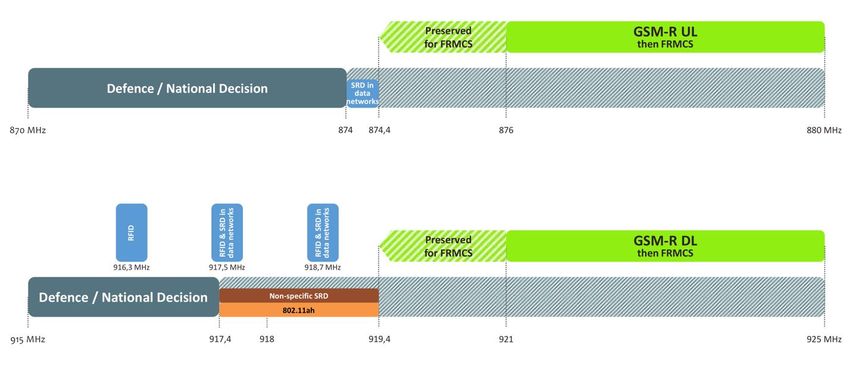
EU Decision on Short Range Radio Devices (SRD) in 874-876 MHz / 915 – 921 MHz is shown in
Figure 2-5. [see RD-1].
Figure 2-5: EU Decision on SRD devices in 874-876 MHz / 915 – 921 MHz [RD-1]
2.7 CBTC vs ERTMS
It is important to note that recent CBTC systems are considered distinct from the European Rail
Traffic Management System (ERTMS), which is another modern, communication-based
signalling system, targeted towards mainline railway operations. Still, however, there are
similarities between the two technologies and, generically, they are actually fairly similar.
CBTC and ERTMS architectures can be divided into four main components. The systems are
typically constituted by
1. onboard and wayside communication equipment,
2. control and command centre with traffic management facilities,
3. trackside or signalling equipment, moreover,
4. the core communication system.
Mainline railway operations make use of wide area network technologies (GSM-R). CBTC is
based on short and medium range solutions. The convergence of CBTC and ERTMS solutions
would be highly beneficial which is a primary focus of the development of both fields. While CBTC
is fragmented but existing and more or less complete set of technologies, ERTMS (level 3 and
above) is mostly the collection of harmonizing ideas. The communication system is the basis for
providing a sustainable, safe operation and ensuring long term interoperability. GSM-R, from
C2CCC_TR_2053_Urban_Rail.doc 28/01/2019 Page 16 of 69CAR 2 CAR Communication Consortium
many reasons, represents a bottleneck in development of future rail systems and it will be phased
out by 2030.
The following table compare the main differences of the two approaches regarding interoperability
and flexibility of the recent solutions and the critical set of implemented features such as ATOs
and the moving block principle. The communication technology used is also rather diverse.
Table 2-1: CBTC and ERTMS system similarities and differences
Due to the big number of stakeholders involved and the wide European heterogenicity of the
affected railways technologies harmonization in standardization is ultimately required. Future
systems must be flexible enough to support these differences without compromising the features
already achieved by each of the individual systems (i.e., ERTMS & CBTC) and everything will
converge towards the standardization of the operational requirements of CBTC and ERTMS
platforms to achieve a seamlessly interoperable European train control system.
C2CCC_TR_2053_Urban_Rail.doc 28/01/2019 Page 17 of 69CAR 2 CAR Communication Consortium 3 Urban Rail communication systems 3.1 CBTC/ERTMS status One the one hand, the trend of applying wireless communication systems in railways – apart from legacy systems (which are usually analogue) that started their development in the early 1980s – is still in its very beginning. In the control and signalling field, several non-harmonized wireless solutions, such as the use of IEEE 802.11-based radio for CBTC/ETCS needs exists in several deployments since several years. In contrast, ERTMS specification for long haul rails combines the GSM-R for internal voice and data communication in the railway environment and the existing ETCS solutions. Harmonization of CBTC in the framework of ERTMS is in a very early stage and the integration of rail systems with other modes of transportation such as with road transportation systems was not considered until recently. As the harmonized European CBTC solutions will be part of final ERTMS specification, the technical work on closing the gap between the road and rail technology domain is an urgent harmonization task. 3.2 Basic CBTC communication requirements Challenges with CBTC stem from the demanding railway application and the special mobility requirements of moving trains. CBTC is ultimately relies on the performance of the communication system. Poor T2G communication performance can result in temporary reduction in speed, a complete train stop, or a train operating in a degraded mode until communications are restored. • Latency and handover time: Basic requirements of radio transmission for CBTC, therefore, are dependability, high priority, the capability of low-to-medium latency communication (latency is in the range of 100 ms and not much higher) and the full-service coverage. Communication holes must be less than 500 msec meaning that if trains lose the connection with the operation (control) centre (i.e., they cannot exchange messages), they will not be authorised to move and must stop in emergency. A roaming handover time of less than 50 ms is essential. From similar reasons a packet loss of less than 0.1 percent is required. • Bandwidth: The typical size of a CBTC control message is 400-500 bytes. A message transmission time of shorter than 100 milliseconds is normally supported. Otherwise, CBTC communications are not specifically bandwidth demanding, they typically generate low data throughput (per train). Given that the typical frequency of messages is about 100-600 milliseconds, data requirement for a CBTC system is typically in the range of 20-40 kbps, but not more than 100 kbps. CBTC is typically a scattered and diverse technology. IEEE 1474.1™ [AD-13] defines a few key and relevant requirements for the CBTC system, however the system itself as a whole is not fully standardized, 1474.1 serves as mere guidelines, and is not strictly followed by the suppliers which C2CCC_TR_2053_Urban_Rail.doc 28/01/2019 Page 18 of 69
CAR 2 CAR Communication Consortium

is one reason why different CBTC solutions are highly incompatible. In particular its
communication system solution is highly implementation dependent.
CBTC does not use a standardized access layer technology neither. A set of different modulation
schemes, MAC and radio bandwidths are used by current implementations.
Though it uses many different technologies: DSSS/TDMA (the CBTC systems installed on the
RATP lines (Paris subway) are based on DSSS proprietary system and TDMA access to channel),
full or modified IEEE 802.11 technology (OFDM based) in various frequencies, nearly all CBTC
installation today work in one of the three, unlicensed ISM bands: 900 MHz, 2.4 GHz, and 5 GHz.
900 MHz is only used in the US. 3GPP TD-LTE (experimentally used in China at 1.8 GHz, not
implemented in Europe yet). Still, however, 802.11 remains the preferred choice since it defends
deployments against obsolescence. Some restrictions on the transmission power do apply,
however.
Using a license-exempt spectrum increases the probability of interference from other users (c.f.
with the widespread proliferation of smartphones and other handheld devices) in the band. The
increasing use of the 2.4 GHz band for CBTC systems by railway operators has therefore raised
concerns and not supported in the future deployments.

3.3 Messages in safety related CBTC (Urban Rail) systems and their
    requirements

CBTC communications can be classified in various categories based on their conditions for
transmission, and also based on their criticality regarding the system performance. Some
messages need to be transmitted and received regularly in order to ensure that on-board and
wayside CBTC subsystems are continuously up-to-date (typically while a train is moving and
updating its location) and to ensure they can 'monitor' each other for a safe evaluation of critical
functions performed by the other interoperable subsystems. For a list of messages see the Table
below.
The main CBTC message types exchanged are:
•   A 'Location Report' message (Uplink) sent by the on-board CBTC of each train to the
    wayside CBTC ('Zone Controller'). These messages help the Zone Controller to continuously
    track the trains' position on a portion of the metro line designated as its 'territory'. It should be
    noted that a train generally communicates with one Zone Controller but it may also have to
    communicate with up to 3 Zone Controllers in some specific configurations (for example when
    the track is subdivided into two diverging branches). The 'Location Report" message includes
    data such as the location of both ends of the train, its speed, the train composition, etc.
•   A functional status message (Uplink) sent by each train to the automatic train supervision
    system, which is less vital but contains more data: it includes information about the train
    position but also any modifications of the rolling stock which can influence the operation, and
    the health status of any on-board redundant equipment, to detect latent failures (hardware
    failures which have no functional impact but reduce the level of redundancy) and fix it before
    a second failure occurs and many other items of functional information, and, when there is a
    driver on a train, some reports on his actions.
•   Messages (Downlink) informing the trains about the status of the variable elements in the
    area where the train is, and in the area that it will reach soon (such as a work zone, a low
    adhesion zone, a malfunctioning signal, etc.). Such information is common to several
    concerned trains which are in the same area.

C2CCC_TR_2053_Urban_Rail.doc                  28/01/2019                                  Page 19 of 69
CAR 2 CAR Communication Consortium
• Messages informing the train about its Movement Authority (downlink): this message
identifies the zone ahead of the train in which it can safely operate without colliding with a
fixed or moving 'obstacle'. Such information is specific to each communicating train. No
messages of that type received during N seconds by a train will trigger an Emergency break
for that train and can also have consequences on following trains.
• It is also sometimes necessary to send quite a high volume of data to a train to update the
track database it is using. To be transparent for train operation, these data are transmitted
from the wayside as the train moves forward (downlink).
Furthermore, when the track is equipped with platform doors, additional messages are
exchanged. These messages necessary to control and ensure safe monitoring of the platform
doors (where existing), also sent periodically when the train is at a station (uplink) and when the
train is approaching and docked at a station (downlink). Very short delays of transmission are
required to ensure fast passenger exchange at the station.
It appears that uplink messages carry status information, in a similar way as C-ITS CAM
messages do. The downlink direction contains different types of messages: status messages
(objective similar to CAM), notification about the area location (objective similar to DENM),
information about Movement of authority ZC (objective similar to SPAT messages) and update of
track database (objective similar to MAP messages).
Direction CBTC application services Period Similar C-ITS
(msec) message
Uplink Location Report to one ZC 200 CAM
Periodic Train Functional Status message 300 CAM
On demand specific status message 300 CAM
Platform Screen Door monitoring and control
approaching, in station and leaving station 100 CAM
Downlink Movement of authority from ZC 600 SPAT
Information about Line from ZC 400 DENM
Track data base update (File transfer) 100 MAP
Request for Health train status 500 DENM
Platform Screen Door 100 CAM
Table 3-1: List of messages used in the CBTC system
According to the topology, the train CBTC system can report to up to three ZCs (Zone Controllers)
simultaneously. The density of the trains depends on several factors such as the train length or
the track configuration of the area, but a good order of magnitude varies typically from 2 to 36
trains in the communications area. Some of the messages exchanged are sent with an identical
content to multiple destinations. Each train receives all the data sent by wayside. CBTC protocol
C2CCC_TR_2053_Urban_Rail.doc 28/01/2019 Page 20 of 69You can also read