SHUTTLE TANKER ADVISORY - OCTOBER 2020 - American Bureau of Shipping (ABS)
←
→
Page content transcription
If your browser does not render page correctly, please read the page content below
SHUTTLE
TANKER
ADVISORY
OCTOBER 2020

               ABS | SHUTTLE TANKER ADVISORY 2020 | i
                                            © Teekay Corporation
——
TABLE OF CONTENTS

INTRODUCTION . .  .  .  .  .  .  .  .  .  .  .  .  .  .  .  .  .  .  .  .  .  .  .  .  .  .  .  .  .  .  .  .  .  .  .  .  .  .  .  .  .  .  .  .  .  .  .  .  .  .  .  .  .  .  .  .  .  .  .  .  .  .  .  .  .  .  .  .  .  . 1

SECTION 1 – OVERVIEW OF SHUTTLE TANKER OPERATIONS .  .  .  .  .  .  .  .  .  .  .  .  .  .  .  .  .  .  .  .  .  .  .  .  .  .  .  .  .  .                                                                                                                                                                 2

        Station Keeping .  .  .  .  .  .  .  .  .  .  .  .  .  .  .  .  .  .  .  .  .  .  .  .  .  .  .  .  .  .  .  .  .  .  .  .  .  .  .  .  .  .  .  .  .  .  .  .  .  .  .  .  .  .  .  .  .  .  .  .  .  .  .  .  .  .  .  .  .  .  .  .  .  .  .  .  .  .  .  .  .  .  .  .  . 2

        Cargo Handling .  .  .  .  .  .  .  .  .  .  .  .  .  .  .  .  .  .  .  .  .  .  .  .  .  .  .  .  .  .  .  .  .  .  .  .  .  .  .  .  .  .  .  .  .  .  .  .  .  .  .  .  .  .  .  .  .  .  .  .  .  .  .  .  .  .  .  .  .  .  .  .  .  .  .  .  .  .  .  .  .  .  .  .  . 3

                   Submerged Turret Loading . .  .  .  .  .  .  .  .  .  .  .  .  .  .  .  .  .  .  .  .  .  .  .  .  .  .  .  .  .  .  .  .  .  .  .  .  .  .  .  .  .  .  .  .  .  .  .  .  .  .  .  .  .  .  .  .  .  .  .  .  .  .  .  .  .  .  .  .  . 3

                   Single Point Mooring .  .  .  .  .  .  .  .  .  .  .  .  .  .  .  .  .  .  .  .  .  .  .  .  .  .  .  .  .  .  .  .  .  .  .  .  .  .  .  .  .  .  .  .  .  .  .  .  .  .  .  .  .  .  .  .  .  .  .  .  .  .  .  .  .  .  .  .  .  .  .  .  .  .  . 3

                   Bow Loading System .  .  .  .  .  .  .  .  .  .  .  .  .  .  .  .  .  .  .  .  .  .  .  .  .  .  .  .  .  .  .  .  .  .  .  .  .  .  .  .  .  .  .  .  .  .  .  .  .  .  .  .  .  .  .  .  .  .  .  .  .  .  .  .  .  .  .  .  .  .  .  .  .  .  .  . 3

        Communications .  .  .  .  .  .  .  .  .  .  .  .  .  .  .  .  .  .  .  .  .  .  .  .  .  .  .  .  .  .  .  .  .  .  .  .  .  .  .  .  .  .  .  .  .  .  .  .  .  .  .  .  .  .  .  .  .  .  .  .  .  .  .  .  .  .  .  .  .  .  .  .  .  .  .  .  .  .  .  .  .  .  .  . 4

        Other Important Considerations .  .  .  .  .  .  .  .  .  .  .  .  .  .  .  .  .  .  .  .  .  .  .  .  .  .  .  .  .  .  .  .  .  .  .  .  .  .  .  .  .  .  .  .  .  .  .  .  .  .  .  .  .  .  .  .  .  .  .  .  .  .  .  .  .  .  .  . 4

        Manning and Training . .  .  .  .  .  .  .  .  .  .  .  .  .  .  .  .  .  .  .  .  .  .  .  .  .  .  .  .  .  .  .  .  .  .  .  .  .  .  .  .  .  .  .  .  .  .  .  .  .  .  .  .  .  .  .  .  .  .  .  .  .  .  .  .  .  .  .  .  .  .  .  .  .  .  .  .  . 5

                   Shuttle Tanker .  .  .  .  .  .  .  .  .  .  .  .  .  .  .  .  .  .  .  .  .  .  .  .  .  .  .  .  .  .  .  .  .  .  .  .  .  .  .  .  .  .  .  .  .  .  .  .  .  .  .  .  .  .  .  .  .  .  .  .  .  .  .  .  .  .  .  .  .  .  .  .  .  .  .  .  .  .  .  .  .  . 5

                   Standby Vessel .  .  .  .  .  .  .  .  .  .  .  .  .  .  .  .  .  .  .  .  .  .  .  .  .  .  .  .  .  .  .  .  .  .  .  .  .  .  .  .  .  .  .  .  .  .  .  .  .  .  .  .  .  .  .  .  .  .  .  .  .  .  .  .  .  .  .  .  .  .  .  .  .  .  .  .  .  .  .  .  .  . 6

                   Offshore Facility .  .  .  .  .  .  .  .  .  .  .  .  .  .  .  .  .  .  .  .  .  .  .  .  .  .  .  .  .  .  .  .  .  .  .  .  .  .  .  .  .  .  .  .  .  .  .  .  .  .  .  .  .  .  .  .  .  .  .  .  .  .  .  .  .  .  .  .  .  .  .  .  .  .  .  .  .  .  .  . 6

        Oil Companies International Marine Forum (OCIMF) Publications .  .  .  .  .  .  .  .  .  .  .  .  .  .  .  .  .  .  .  .  .  .  .  .  .  .  .  .  .  .  .  .  . 6

SECTION 2 – REGIONAL CONSIDERATIONS .  .  .  .  .  .  .  .  .  .  .  .  .  .  .  .  .  .  .  .  .  .  .  .  .  .  .  .  .  .  .  .  .  .  .  .  .  .  .  .  .  .  .  .  .                                                                                                                                  7

        Brazil .  .  .  .  .  .  .  .  .  .  .  .  .  .  .  .  .  .  .  .  .  .  .  .  .  .  .  .  .  .  .  .  .  .  .  .  .  .  .  .  .  .  .  .  .  .  .  .  .  .  .  .  .  .  .  .  .  .  .  .  .  .  .  .  .  .  .  .  .  .  .  .  .  .  .  .  .  .  .  .  .  .  .  .  .  .  .  .  .  .  .  .  .  .  .  . 7

                   Main Operational Particulars .  .  .  .  .  .  .  .  .  .  .  .  .  .  .  .  .  .  .  .  .  .  .  .  .  .  .  .  .  .  .  .  .  .  .  .  .  .  .  .  .  .  .  .  .  .  .  .  .  .  .  .  .  .  .  .  .  .  .  .  .  .  .  .  .  .  . 7

                   Maintenance Challenges .  .  .  .  .  .  .  .  .  .  .  .  .  .  .  .  .  .  .  .  .  .  .  .  .  .  .  .  .  .  .  .  .  .  .  .  .  .  .  .  .  .  .  .  .  .  .  .  .  .  .  .  .  .  .  .  .  .  .  .  .  .  .  .  .  .  .  .  .  .  .  . 7

                   Brazilian Flag Considerations .  .  .  .  .  .  .  .  .  .  .  .  .  .  .  .  .  .  .  .  .  .  .  .  .  .  .  .  .  .  .  .  .  .  .  .  .  .  .  .  .  .  .  .  .  .  .  .  .  .  .  .  .  .  .  .  .  .  .  .  .  .  .  .  .  .  . 7

        North Sea .  .  .  .  .  .  .  .  .  .  .  .  .  .  .  .  .  .  .  .  .  .  .  .  .  .  .  .  .  .  .  .  .  .  .  .  .  .  .  .  .  .  .  .  .  .  .  .  .  .  .  .  .  .  .  .  .  .  .  .  .  .  .  .  .  .  .  .  .  .  .  .  .  .  .  .  .  .  .  .  .  .  .  .  .  .  .  .  .  .  . 7

                   Norwegian Oil and Gas Recommended Guidelines for Offshore Loading
                   Shuttle Tankers, Guideline No . 140 . .  .  .  .  .  .  .  .  .  .  .  .  .  .  .  .  .  .  .  .  .  .  .  .  .  .  .  .  .  .  .  .  .  .  .  .  .  .  .  .  .  .  .  .  .  .  .  .  .  .  .  .  .  .  .  .  .  .  .  .  . 7

                   Cold Climates .  .  .  .  .  .  .  .  .  .  .  .  .  .  .  .  .  .  .  .  .  .  .  .  .  .  .  .  .  .  .  .  .  .  .  .  .  .  .  .  .  .  .  .  .  .  .  .  .  .  .  .  .  .  .  .  .  .  .  .  .  .  .  .  .  .  .  .  .  .  .  .  .  .  .  .  .  .  .  .  .  .  . 8

        U.S. Gulf of Mexico. .  .  .  .  .  .  .  .  .  .  .  .  .  .  .  .  .  .  .  .  .  .  .  .  .  .  .  .  .  .  .  .  .  .  .  .  .  .  .  .  .  .  .  .  .  .  .  .  .  .  .  .  .  .  .  .  .  .  .  .  .  .  .  .  .  .  .  .  .  .  .  .  .  .  .  .  .  .  .  .  .  . 8

                   Alternate Compliance Program .  .  .  .  .  .  .  .  .  .  .  .  .  .  .  .  .  .  .  .  .  .  .  .  .  .  .  .  .  .  .  .  .  .  .  .  .  .  .  .  .  .  .  .  .  .  .  .  .  .  .  .  .  .  .  .  .  .  .  .  .  .  .  .  . 8

SECTION 3 – DESIGN AND OPERATIONAL ISSUES . .  .  .  .  .  .  .  .  .  .  .  .  .  .  .  .  .  .  .  .  .  .  .  .  .  .  .  .  .  .  .  .  .  .  .  .  .  .  .                                                                                                                                            9

        Brazil .  .  .  .  .  .  .  .  .  .  .  .  .  .  .  .  .  .  .  .  .  .  .  .  .  .  .  .  .  .  .  .  .  .  .  .  .  .  .  .  .  .  .  .  .  .  .  .  .  .  .  .  .  .  .  .  .  .  .  .  .  .  .  .  .  .  .  .  .  .  .  .  .  .  .  .  .  .  .  .  .  .  .  .  .  .  .  .  .  .  .  .  .  .  .  . 9

        North Sea .  .  .  .  .  .  .  .  .  .  .  .  .  .  .  .  .  .  .  .  .  .  .  .  .  .  .  .  .  .  .  .  .  .  .  .  .  .  .  .  .  .  .  .  .  .  .  .  .  .  .  .  .  .  .  .  .  .  .  .  .  .  .  .  .  .  .  .  .  .  .  .  .  .  .  .  .  .  .  .  .  .  .  .  .  .  .  .  .  .  . 11

SECTION 4 – TYPICAL CLASS NOTATIONS .  .  .  .  .  .  .  .  .  .  .  .  .  .  .  .  .  .  .  .  .  .  .  .  .  .  .  .  .  .  .  .  .  .  .  .  .  .  .  .  .  .  .  .  .  . 15

        General . .  .  .  .  .  .  .  .  .  .  .  .  .  .  .  .  .  .  .  .  .  .  .  .  .  .  .  .  .  .  .  .  .  .  .  .  .  .  .  .  .  .  .  .  .  .  .  .  .  .  .  .  .  .  .  .  .  .  .  .  .  .  .  .  .  .  .  .  .  .  .  .  .  .  .  .  .  .  .  .  .  .  .  .  .  .  .  .  .  .  .  .     15

        Machinery and Control Systems .  .  .  .  .  .  .  .  .  .  .  .  .  .  .  .  .  .  .  .  .  .  .  .  .  .  .  .  .  .  .  .  .  .  .  .  .  .  .  .  .  .  .  .  .  .  .  .  .  .  .  .  .  .  .  .  .  .  .  .  .  .  .  .  .  .  .                                                            15

        Ballast Water Treatment and Exchange .  .  .  .  .  .  .  .  .  .  .  .  .  .  .  .  .  .  .  .  .  .  .  .  .  .  .  .  .  .  .  .  .  .  .  .  .  .  .  .  .  .  .  .  .  .  .  .  .  .  .  .  .  .  .  .  .  .  .  .                                                                          15

        Lifting Appliances .  .  .  .  .  .  .  .  .  .  .  .  .  .  .  .  .  .  .  .  .  .  .  .  .  .  .  .  .  .  .  .  .  .  .  .  .  .  .  .  .  .  .  .  .  .  .  .  .  .  .  .  .  .  .  .  .  .  .  .  .  .  .  .  .  .  .  .  .  .  .  .  .  .  .  .  .  .  .  .  .                             16
SECTION 5 – LOADING/UNLOADING SYSTEMS . .  .  .  .  .  .  .  .  .  .  .  .  .  .  .  .  .  .  .  .  .  .  .  .  .  .  .  .  .  .  .  .  .  .  .  .  .  .  .  .  .  . 17

       BLU (Bow Loading/Unloading) and SLU (Stern Loading And Unloading) Notation . .  .  .  .  .  .  .  .  .  .  .  .  .  .  .  . 17

       Single Point Mooring Arrangement . .  .  .  .  .  .  .  .  .  .  .  .  .  .  .  .  .  .  .  .  .  .  .  .  .  .  .  .  .  .  .  .  .  .  .  .  .  .  .  .  .  .  .  .  .  .  .  .  .  .  .  .  .  .  .  .  .  .  .  .  .  .  .  . 17

SECTION 6 – DYNAMIC POSITIONING AND PROPULSION REDUNDANCY .  .  .  .  .  .  .  .  .  .  .  .  .  .  .  .  .  .  .  . 18

       Dynamic Positioning Systems . .  .  .  .  .  .  .  .  .  .  .  .  .  .  .  .  .  .  .  .  .  .  .  .  .  .  .  .  .  .  .  .  .  .  .  .  .  .  .  .  .  .  .  .  .  .  .  .  .  .  .  .  .  .  .  .  .  .  .  .  .  .  .  .  .  .  .  .  .                                                 18

       Enhanced System Notations .  .  .  .  .  .  .  .  .  .  .  .  .  .  .  .  .  .  .  .  .  .  .  .  .  .  .  .  .  .  .  .  .  .  .  .  .  .  .  .  .  .  .  .  .  .  .  .  .  .  .  .  .  .  .  .  .  .  .  .  .  .  .  .  .  .  .  .  .  .  .                                               21

       SKP (Station Keeping Performance) Notation .  .  .  .  .  .  .  .  .  .  .  .  .  .  .  .  .  .  .  .  .  .  .  .  .  .  .  .  .  .  .  .  .  .  .  .  .  .  .  .  .  .  .  .  .  .  .  .  .  .  .  .  .  .                                                                                 21

       APS (Athwartship Thruster) Notation . .  .  .  .  .  .  .  .  .  .  .  .  .  .  .  .  .  .  .  .  .  .  .  .  .  .  .  .  .  .  .  .  .  .  .  .  .  .  .  .  .  .  .  .  .  .  .  .  .  .  .  .  .  .  .  .  .  .  .  .  .                                                                 21

       Propulsion Redundancy. .  .  .  .  .  .  .  .  .  .  .  .  .  .  .  .  .  .  .  .  .  .  .  .  .  .  .  .  .  .  .  .  .  .  .  .  .  .  .  .  .  .  .  .  .  .  .  .  .  .  .  .  .  .  .  .  .  .  .  .  .  .  .  .  .  .  .  .  .  .  .  .  .  .  .                                      21

SECTION 7 – HULL CONSTRUCTION AND EQUIPMENT .  .  .  .  .  .  .  .  .  .  .  .  .  .  .  .  .  .  .  .  .  .  .  .  .  .  .  .  .  .  .  .  .  .  .                                                                                                                                              24

       Structures .  .  .  .  .  .  .  .  .  .  .  .  .  .  .  .  .  .  .  .  .  .  .  .  .  .  .  .  .  .  .  .  .  .  .  .  .  .  .  .  .  .  .  .  .  .  .  .  .  .  .  .  .  .  .  .  .  .  .  .  .  .  .  .  .  .  .  .  .  .  .  .  .  .  .  .  .  .  .  .  .  .  .  .  .  .  .  .  .  . 24

       Anchoring . . . . . . . . . . . . . . . . . . . . . . . . . . . . . . . . . . . . . . . . . . . . . . . . . . . . . . . . . . . . . . . . . . . . . . . . . . . . . . . . . . . . . . . . . . 24

       Helicopter Decks .  .  .  .  .  .  .  .  .  .  .  .  .  .  .  .  .  .  .  .  .  .  .  .  .  .  .  .  .  .  .  .  .  .  .  .  .  .  .  .  .  .  .  .  .  .  .  .  .  .  .  .  .  .  .  .  .  .  .  .  .  .  .  .  .  .  .  .  .  .  .  .  .  .  .  .  .  .  .  .  .  .  . 24

       Hull Condition Monitoring . . . . . . . . . . . . . . . . . . . . . . . . . . . . . . . . . . . . . . . . . . . . . . . . . . . . . . . . . . . . . . . . . . . . . . . . . 24

SECTION 8 – OTHER MACHINERY AND SYSTEMS .  .  .  .  .  .  .  .  .  .  .  .  .  .  .  .  .  .  .  .  .  .  .  .  .  .  .  .  .  .  .  .  .  .  .  .  .  .  .  .                                                                                                                                   26

       Vapor Emission Control (VEC and VEC-L) .  .  .  .  .  .  .  .  .  .  .  .  .  .  .  .  .  .  .  .  .  .  .  .  .  .  .  .  .  .  .  .  .  .  .  .  .  .  .  .  .  .  .  .  .  .  .  .  .  .  .  .  .  .  .  .  .  . 26

       Enhanced Shaft Alignment .  .  .  .  .  .  .  .  .  .  .  .  .  .  .  .  .  .  .  .  .  .  .  .  .  .  .  .  .  .  .  .  .  .  .  .  .  .  .  .  .  .  .  .  .  .  .  .  .  .  .  .  .  .  .  .  .  .  .  .  .  .  .  .  .  .  .  .  .  .  .  . 26

       High Voltage Shore Connection System .  .  .  .  .  .  .  .  .  .  .  .  .  .  .  .  .  .  .  .  .  .  .  .  .  .  .  .  .  .  .  .  .  .  .  .  .  .  .  .  .  .  .  .  .  .  .  .  .  .  .  .  .  .  .  .  .  .  .  . 26

       Tailshaft Condition Monitoring .  .  .  .  .  .  .  .  .  .  .  .  .  .  .  .  .  .  .  .  .  .  .  .  .  .  .  .  .  .  .  .  .  .  .  .  .  .  .  .  .  .  .  .  .  .  .  .  .  .  .  .  .  .  .  .  .  .  .  .  .  .  .  .  .  .  . 26

SECTION 9 – SAFETY AND HUMAN FACTORS .  .  .  .  .  .  .  .  .  .  .  .  .  .  .  .  .  .  .  .  .  .  .  .  .  .  .  .  .  .  .  .  .  .  .  .  .  .  .  .  .  .  .                                                                                                                             28

       Safety .  .  .  .  .  .  .  .  .  .  .  .  .  .  .  .  .  .  .  .  .  .  .  .  .  .  .  .  .  .  .  .  .  .  .  .  .  .  .  .  .  .  .  .  .  .  .  .  .  .  .  .  .  .  .  .  .  .  .  .  .  .  .  .  .  .  .  .  .  .  .  .  .  .  .  .  .  .  .  .  .  .  .  .  .  .  .  .  .  .  .  .  .  . 28

       Enhanced Fire Protection .  .  .  .  .  .  .  .  .  .  .  .  .  .  .  .  .  .  .  .  .  .  .  .  .  .  .  .  .  .  .  .  .  .  .  .  .  .  .  .  .  .  .  .  .  .  .  .  .  .  .  .  .  .  .  .  .  .  .  .  .  .  .  .  .  .  .  .  .  .  .  .  .  . 28

       Human Factors .  .  .  .  .  .  .  .  .  .  .  .  .  .  .  .  .  .  .  .  .  .  .  .  .  .  .  .  .  .  .  .  .  .  .  .  .  .  .  .  .  .  .  .  .  .  .  .  .  .  .  .  .  .  .  .  .  .  .  .  .  .  .  .  .  .  .  .  .  .  .  .  .  .  .  .  .  .  .  .  .  .  .  .  . 28

                  Habitability .  .  .  .  .  .  .  .  .  .  .  .  .  .  .  .  .  .  .  .  .  .  .  .  .  .  .  .  .  .  .  .  .  .  .  .  .  .  .  .  .  .  .  .  .  .  .  .  .  .  .  .  .  .  .  .  .  .  .  .  .  .  .  .  .  .  .  .  .  .  .  .  .  .  .  .  .  .  .  .  .  .  .  . 28

                  Ergonomics. .  .  .  .  .  .  .  .  .  .  .  .  .  .  .  .  .  .  .  .  .  .  .  .  .  .  .  .  .  .  .  .  .  .  .  .  .  .  .  .  .  .  .  .  .  .  .  .  .  .  .  .  .  .  .  .  .  .  .  .  .  .  .  .  .  .  .  .  .  .  .  .  .  .  .  .  .  .  .  .  .  .  .  . 29

                  Navigation Bridge .  .  .  .  .  .  .  .  .  .  .  .  .  .  .  .  .  .  .  .  .  .  .  .  .  .  .  .  .  .  .  .  .  .  .  .  .  .  .  .  .  .  .  .  .  .  .  .  .  .  .  .  .  .  .  .  .  .  .  .  .  .  .  .  .  .  .  .  .  .  .  .  .  .  .  .  .  . 29

                  Means of Access . .  .  .  .  .  .  .  .  .  .  .  .  .  .  .  .  .  .  .  .  .  .  .  .  .  .  .  .  .  .  .  .  .  .  .  .  .  .  .  .  .  .  .  .  .  .  .  .  .  .  .  .  .  .  .  .  .  .  .  .  .  .  .  .  .  .  .  .  .  .  .  .  .  .  .  .  .  .  . 30

SECTION 10 – ENVIRONMENT . .  .  .  .  .  .  .  .  .  .  .  .  .  .  .  .  .  .  .  .  .  .  .  .  .  .  .  .  .  .  .  .  .  .  .  .  .  .  .  .  .  .  .  .  .  .  .  .  .  .  .  .  .  .  .  .  . 31

       Cold Climates .  .  .  .  .  .  .  .  .  .  .  .  .  .  .  .  .  .  .  .  .  .  .  .  .  .  .  .  .  .  .  .  .  .  .  .  .  .  .  .  .  .  .  .  .  .  .  .  .  .  .  .  .  .  .  .  .  .  .  .  .  .  .  .  .  .  .  .  .  .  .  .  .  .  .  .  .  .  .  .  .  .  .  .  .  .              31

                  Ice Classes .  .  .  .  .  .  .  .  .  .  .  .  .  .  .  .  .  .  .  .  .  .  .  .  .  .  .  .  .  .  .  .  .  .  .  .  .  .  .  .  .  .  .  .  .  .  .  .  .  .  .  .  .  .  .  .  .  .  .  .  .  .  .  .  .  .  .  .  .  .  .  .  .  .  .  .  .  .  .  .  .  .  .  .  .  .     31

                  Operation in Low-Temperature Environments. .  .  .  .  .  .  .  .  .  .  .  .  .  .  .  .  .  .  .  .  .  .  .  .  .  .  .  .  .  .  .  .  .  .  .  .  .  .  .  .  .  .  .  .  .  .  .  .                                                                                        31

                  Ice Loads Monitoring. .  .  .  .  .  .  .  .  .  .  .  .  .  .  .  .  .  .  .  .  .  .  .  .  .  .  .  .  .  .  .  .  .  .  .  .  .  .  .  .  .  .  .  .  .  .  .  .  .  .  .  .  .  .  .  .  .  .  .  .  .  .  .  .  .  .  .  .  .  .  .  .  .  . 32

       Emissions And Pollution Control . . . . . . . . . . . . . . . . . . . . . . . . . . . . . . . . . . . . . . . . . . . . . . . . . . . . . . . . . . . . . . . . . . . 33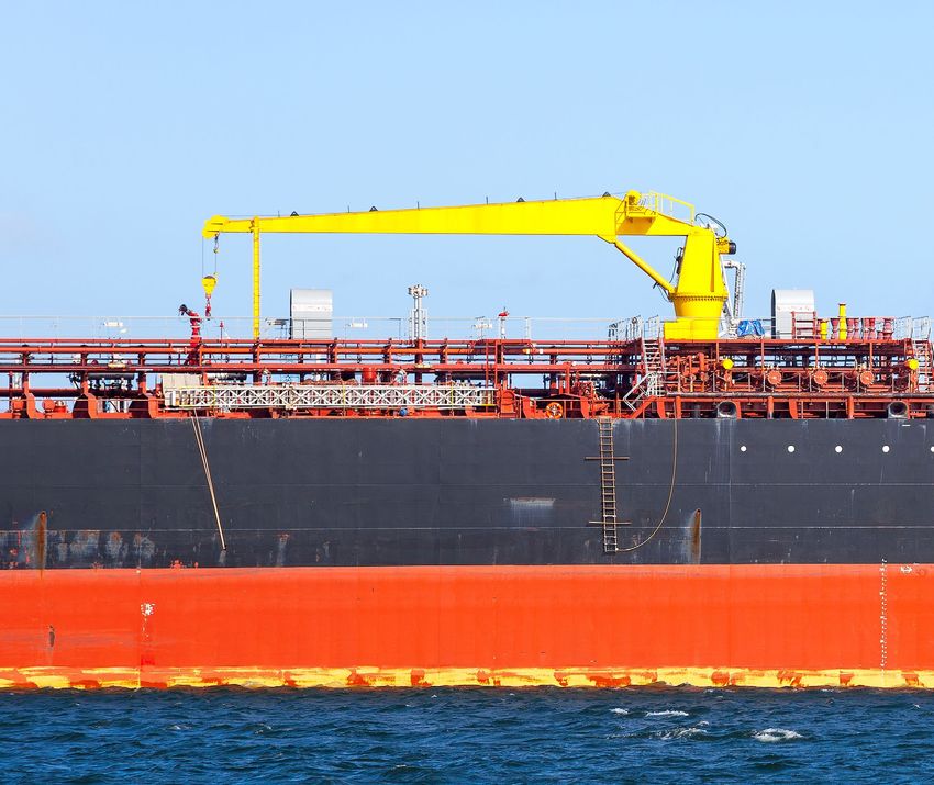
——
TABLE OF CONTENTS, CONTINUED

                 Exhaust Emission Reduction .  .  .  .  .  .  .  .  .  .  .  .  .  .  .  .  .  .  .  .  .  .  .  .  .  .  .  .  .  .  .  .  .  .  .  .  .  .  .  .  .  .  .  .  .  .  .  .  .  .  .  .  .  .  .  .  .  .  .  .  .  .  .  .  .  .  . 33

                 Energy Efficiency Design Index (EEDI) and the IMO GHG Strategy. .  .  .  .  .  .  .  .  .  .  .  .  .  .  .  .  .  .  .  .  .  .  .  .  .  .  .  . 33

                 EU MRV (Monitoring, Reporting and Verification) of Fuel Consumption and
                 IMO DCS (Data Collection System) .  .  .  .  .  .  .  .  .  .  .  .  .  .  .  .  .  .  .  .  .  .  .  .  .  .  .  .  .  .  .  .  .  .  .  .  .  .  .  .  .  .  .  .  .  .  .  .  .  .  .  .  .  .  .  .  .  .  .  .  . 34

                 Environmental Protection .  .  .  .  .  .  .  .  .  .  .  .  .  .  .  .  .  .  .  .  .  .  .  .  .  .  .  .  .  .  .  .  .  .  .  .  .  .  .  .  .  .  .  .  .  .  .  .  .  .  .  .  .  .  .  .  .  .  .  .  .  .  .  .  .  .  .  .  . 34

                 Hazardous Materials .  .  .  .  .  .  .  .  .  .  .  .  .  .  .  .  .  .  .  .  .  .  .  .  .  .  .  .  .  .  .  .  .  .  .  .  .  .  .  .  .  .  .  .  .  .  .  .  .  .  .  .  .  .  .  .  .  .  .  .  .  .  .  .  .  .  .  .  .  .  .  .  .  .  . 35

                 Protection of Fuel and Lubricating Oil Tanks .  .  .  .  .  .  .  .  .  .  .  .  .  .  .  .  .  .  .  .  .  .  .  .  .  .  .  .  .  .  .  .  .  .  .  .  .  .  .  .  .  .  .  .  .  .  .  .  .  . 35

       Noise Control . . . . . . . . . . . . . . . . . . . . . . . . . . . . . . . . . . . . . . . . . . . . . . . . . . . . . . . . . . . . . . . . . . . . . . . . . . . . . . . . . . . . . . . 35

SECTION 11 – ADDITIONAL SURVEY AND INSPECTION CONSIDERATIONS . .  .  .  .  .  .  .  .  .  .  .  .  .  .  .  .  .                                                                                                                                                                             36

       Hull Inspection .  .  .  .  .  .  .  .  .  .  .  .  .  .  .  .  .  .  .  .  .  .  .  .  .  .  .  .  .  .  .  .  .  .  .  .  .  .  .  .  .  .  .  .  .  .  .  .  .  .  .  .  .  .  .  .  .  .  .  .  .  .  .  .  .  .  .  .  .  .  .  .  .  .  .  .  .  .  .  .  .  .  .  . 36

       Underwater Inspection in Lieu of Drydocking .  .  .  .  .  .  .  .  .  .  .  .  .  .  .  .  .  .  .  .  .  .  .  .  .  .  .  .  .  .  .  .  .  .  .  .  .  .  .  .  .  .  .  .  .  .  .  .  .  .  .  .  . 36

       Condition Assessment Program (CAP) .  .  .  .  .  .  .  .  .  .  .  .  .  .  .  .  .  .  .  .  .  .  .  .  .  .  .  .  .  .  .  .  .  .  .  .  .  .  .  .  .  .  .  .  .  .  .  .  .  .  .  .  .  .  .  .  .  .  .  .  . 36

                 Process .  .  .  .  .  .  .  .  .  .  .  .  .  .  .  .  .  .  .  .  .  .  .  .  .  .  .  .  .  .  .  .  .  .  .  .  .  .  .  .  .  .  .  .  .  .  .  .  .  .  .  .  .  .  .  .  .  .  .  .  .  .  .  .  .  .  .  .  .  .  .  .  .  .  .  .  .  .  .  .  .  .  .  .  .  .  .  .  . 36

                 Benefits .  .  .  .  .  .  .  .  .  .  .  .  .  .  .  .  .  .  .  .  .  .  .  .  .  .  .  .  .  .  .  .  .  .  .  .  .  .  .  .  .  .  .  .  .  .  .  .  .  .  .  .  .  .  .  .  .  .  .  .  .  .  .  .  .  .  .  .  .  .  .  .  .  .  .  .  .  .  .  .  .  .  .  .  .  .  .  . 36

       Preventative Maintenance Program (PMP). .  .  .  .  .  .  .  .  .  .  .  .  .  .  .  .  .  .  .  .  .  .  .  .  .  .  .  .  .  .  .  .  .  .  .  .  .  .  .  .  .  .  .  .  .  .  .  .  .  .  .  .  .  .  .  . 36

       Remote Surveys .  .  .  .  .  .  .  .  .  .  .  .  .  .  .  .  .  .  .  .  .  .  .  .  .  .  .  .  .  .  .  .  .  .  .  .  .  .  .  .  .  .  .  .  .  .  .  .  .  .  .  .  .  .  .  .  .  .  .  .  .  .  .  .  .  .  .  .  .  .  .  .  .  .  .  .  .  .  .  .  .  .  .  . 38

SECTION 12 – NEW TECHNOLOGIES .  .  .  .  .  .  .  .  .  .  .  .  .  .  .  .  .  .  .  .  .  .  .  .  .  .  .  .  .  .  .  .  .  .  .  .  .  .  .  .  .  .  .  .  .  .  .  .  .  .  .                                                                                                        39

       Low Carbon Shipping Outlook .  .  .  .  .  .  .  .  .  .  .  .  .  .  .  .  .  .  .  .  .  .  .  .  .  .  .  .  .  .  .  .  .  .  .  .  .  .  .  .  .  .  .  .  .  .  .  .  .  .  .  .  .  .  .  .  .  .  .  .  .  .  .  .  .  .  .  .  . 39

       Reliquefaction of Volatile Organic Compounds (VOC) . .  .  .  .  .  .  .  .  .  .  .  .  .  .  .  .  .  .  .  .  .  .  .  .  .  .  .  .  .  .  .  .  .  .  .  .  .  .  .  .  .  .  .  . 39

       Gas and Other Low Flashpoint Fuels .  .  .  .  .  .  .  .  .  .  .  .  .  .  .  .  .  .  .  .  .  .  .  .  .  .  .  .  .  .  .  .  .  .  .  .  .  .  .  .  .  .  .  .  .  .  .  .  .  .  .  .  .  .  .  .  .  .  .  .  .  .  . 39

       Hybrid Power Systems .  .  .  .  .  .  .  .  .  .  .  .  .  .  .  .  .  .  .  .  .  .  .  .  .  .  .  .  .  .  .  .  .  .  .  .  .  .  .  .  .  .  .  .  .  .  .  .  .  .  .  .  .  .  .  .  .  .  .  .  .  .  .  .  .  .  .  .  .  .  .  .  .  .  .  .  . 39

       Fuel Cell Power Systems . .  .  .  .  .  .  .  .  .  .  .  .  .  .  .  .  .  .  .  .  .  .  .  .  .  .  .  .  .  .  .  .  .  .  .  .  .  .  .  .  .  .  .  .  .  .  .  .  .  .  .  .  .  .  .  .  .  .  .  .  .  .  .  .  .  .  .  .  .  .  .  .  .  .  . 40

       Energy Storage Systems .  .  .  .  .  .  .  .  .  .  .  .  .  .  .  .  .  .  .  .  .  .  .  .  .  .  .  .  .  .  .  .  .  .  .  .  .  .  .  .  .  .  .  .  .  .  .  .  .  .  .  .  .  .  .  .  .  .  .  .  .  .  .  .  .  .  .  .  .  .  .  .  .  .  .  . 40

       DC Power Distribution .  .  .  .  .  .  .  .  .  .  .  .  .  .  .  .  .  .  .  .  .  .  .  .  .  .  .  .  .  .  .  .  .  .  .  .  .  .  .  .  .  .  .  .  .  .  .  .  .  .  .  .  .  .  .  .  .  .  .  .  .  .  .  .  .  .  .  .  .  .  .  .  .  .  .  .  . 40

       Cybersafety . .  .  .  .  .  .  .  .  .  .  .  .  .  .  .  .  .  .  .  .  .  .  .  .  .  .  .  .  .  .  .  .  .  .  .  .  .  .  .  .  .  .  .  .  .  .  .  .  .  .  .  .  .  .  .  .  .  .  .  .  .  .  .  .  .  .  .  .  .  .  .  .  .  .  .  .  .  .  .  .  .  .  .  .  .  .  .  . 40

       Software Systems .  .  .  .  .  .  .  .  .  .  .  .  .  .  .  .  .  .  .  .  .  .  .  .  .  .  .  .  .  .  .  .  .  .  .  .  .  .  .  .  .  .  .  .  .  .  .  .  .  .  .  .  .  .  .  .  .  .  .  .  .  .  .  .  .  .  .  .  .  .  .  .  .  .  .  .  .  .  .  .  .  .                   41

       Smart Vessels .  .  .  .  .  .  .  .  .  .  .  .  .  .  .  .  .  .  .  .  .  .  .  .  .  .  .  .  .  .  .  .  .  .  .  .  .  .  .  .  .  .  .  .  .  .  .  .  .  .  .  .  .  .  .  .  .  .  .  .  .  .  .  .  .  .  .  .  .  .  .  .  .  .  .  .  .  .  .  .  .  .  .  .  .  .          41

       Digital Solutions .  .  .  .  .  .  .  .  .  .  .  .  .  .  .  .  .  .  .  .  .  .  .  .  .  .  .  .  .  .  .  .  .  .  .  .  .  .  .  .  .  .  .  .  .  .  .  .  .  .  .  .  .  .  .  .  .  .  .  .  .  .  .  .  .  .  .  .  .  .  .  .  .  .  .  .  .  .  .  .  .  .  . 42

       Digital Innovations . .  .  .  .  .  .  .  .  .  .  .  .  .  .  .  .  .  .  .  .  .  .  .  .  .  .  .  .  .  .  .  .  .  .  .  .  .  .  .  .  .  .  .  .  .  .  .  .  .  .  .  .  .  .  .  .  .  .  .  .  .  .  .  .  .  .  .  .  .  .  .  .  .  .  .  .  .  .  .  . 42

       Next-Generation Marine Fleet Management Services .  .  .  .  .  .  .  .  .  .  .  .  .  .  .  .  .  .  .  .  .  .  .  .  .  .  .  .  .  .  .  .  .  .  .  .  .  .  .  .  .  .  .  .  . 42

       Freedom. .  .  .  .  .  .  .  .  .  .  .  .  .  .  .  .  .  .  .  .  .  .  .  .  .  .  .  .  .  .  .  .  .  .  .  .  .  .  .  .  .  .  .  .  .  .  .  .  .  .  .  .  .  .  .  .  .  .  .  .  .  .  .  .  .  .  .  .  .  .  .  .  .  .  .  .  .  .  .  .  .  .  .  .  .  .  .  .  .  .  . 43

APPENDIX A - REFERENCES . .  .  .  .  .  .  .  .  .  .  .  .  .  .  .  .  .  .  .  .  .  .  .  .  .  .  .  .  .  .  .  .  .  .  .  .  .  .  .  .  .  .  .  .  .  .  .  .  .  .  .  .  .  .  .  .  . 44

While ABS uses reasonable efforts to accurately describe and update the information in this Advisory, ABS makes no warranties or representations as to its accuracy, currency or
completeness. ABS assumes no liability or responsibility for any errors or omissions in the content of this Advisory. To the extent permitted by applicable law, everything in this Advisory
is provided “as is” without warranty of any kind, either expressed or implied, including, but not limited to, the implied warranties of merchantability, fitness for a particular purpose, or
noninfringement. In no event will ABS be liable for any damages whatsoever, including special, indirect, consequential or incidental damages or damages for loss of profits, revenue or use,
whether brought in contract or tort, arising out of or connected with this Advisory or the use or reliance upon any of the content or any information contained herein.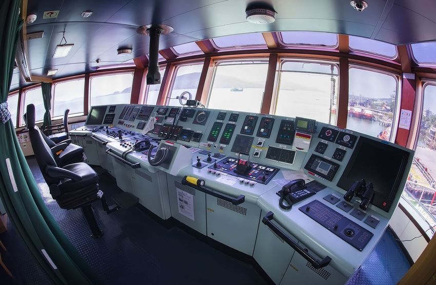
——
INTRODUCTION
ABS is the Class leader in the tanker industry with over a quarter of the worldwide existing fleet and orderbook.
ABS has extensive global experience in all sizes of tankers. Its safety record and leading Port State Control (PSC)
ranking are a testament to ABS’s commitment and focus on its mission.

ABS has a dedicated global workforce, with over 1,200 Surveyors and 500 Engineers positioned in 200 offices in 70
counties worldwide. ABS is looked upon as a trusted service provider not only for classification services but also
for leading technology and research geared toward improving vessel performance.

Shuttle tankers are primarily employed in offshore oil and gas fields. As the Class leader in the offshore industry
with a significant majority of Mobile Offshore Drilling Units (MODUs) currently under ABS class, our extensive
network of experienced Surveyors and Engineers are well-positioned to support client operations. In a continually
evolving market, ABS works alongside its partners to tackle the most pressing technical, operational, and
regulatory challenges to help the industry operate safely, securely, and responsibly.

This Advisory provides an overview of shuttle tanker design and operation. It discusses regional considerations for
shuttle tankers operating in Brazil, the North Sea, and the Gulf of Mexico. It explains how ABS optional notations
complement class and statutory requirements to fulfill regional and operational requirements. We also identify
requirements that are not covered by our class offerings that may be addressed by newbuild specifications or
operational policies. We conclude by discussing new technologies that have already started to impact the shuttle
tanker market.

                                                                                                   © G-Valeriy/Shutterstock

                                                                               ABS | SHUTTLE TANKER ADVISORY 2020 | 1
——
SECTION 1 – OVERVIEW OF SHUTTLE
TANKER OPERATIONS

                                                                                                 © Plamen Galabov/Shutterstock

Shuttle Tankers are a specialized type of tanker designed to load cargo from an offshore facility or a vessel of large
size that cannot transit to the destination due to draft restrictions. Shuttle tankers are often used as an alternative
to pipelines where harsh environments, remote location or water depth prevent a pipeline installation.

The offshore facility that a shuttle tanker loads from is typically a Single Point Mooring (SPM) buoy or a Floating
(Production) Storage and Offloading (F(P)SO) unit. Some F(P)SOs are turret moored, which allows them to
weathervane around the turret depending on current, wave, and wind direction. Some F(P)SOs are spread moored,
which means that they have mooring lines off their bow and stern that maintain their heading despite current,
wave, and wind patterns. A shuttle tanker must be able to safely moor and load cargo from these types of units.

All of this means that station keeping, cargo handling and communication between the shuttle tanker and
offshore loading facility are vital to a shuttle tanker’s safe operation.

STATION KEEPING
The Dynamic Positioning System is one of the most important or vital systems on a shuttle tanker. The shuttle
tanker must maintain position during approach, loading, and departure, even in less than ideal weather
conditions. To address station keeping requirements, ABS offers a full suite of Dynamic Positioning Notations.

2 | SHUTTLE TANKER ADVISORY 2020 | ABS
Most shuttle tankers have a minimum of DPS-2 dynamic positioning system. Additional complementary
Notations, including Enhanced System Notation, Station Keeping Notation, and Athwartship Thruster Notations
are also available and are discussed in Section 6.

To provide further propulsion safety, some shuttle tankers incorporate propulsion redundancy, with various
combinations of multiple engines, engine rooms, and propellers. Propulsion redundancy is also discussed in
Section 6.

CARGO HANDLING
SUBMERGED TURRET LOADING
Depending on the offshore field’s infrastructure, shuttle tankers may need to accommodate different loading
systems. Some shuttle tankers accommodate a Submerged Turret Loading (STL) system with a submerged buoy
that connects through a cone-shaped turret in the keel of the shuttle tanker. This system is best suited for loading
in areas with high sea states.

The buoy is spread moored to the seafloor and normally floats in a neutral position about 40 m below the surface.
The mooring lines, risers, and umbilicals are connected to a turret nested inside the buoy. The turret is free to
rotate inside the buoy, which allows the shuttle tanker to weathervane while connected to the buoy.

The following is a high-level overview of the loading operation using the STL:
1.	 The shuttle tanker locates the buoy using hydroacoustic transponders and TV cameras.
2.	 A messenger line from the shuttle tanker is connected to a messenger line connected to the submerged buoy,
    and the buoy is pulled up through the conical opening in the shuttle tanker bow.
3.	 The buoy is pulled into the hull and locked in place by hydraulic actuators.
4.	 The ship’s loading manifold is lowered onto and connected to the buoy.
5.	 Loading of oil can begin.
6.	 Once loading has completed, the tanker releases the buoy, which sinks back down to the neutral position.

SINGLE POINT MOORING
A Single Point Mooring (SPM) Buoy consists of three components: the anchoring system, the buoy body, and
the product transfer system. The buoy is spread moored to the seabed. A Pipeline End and Manifold (PLEM) on
the seabed connects to the SPM through a riser. The buoy loading mechanism rotates to allow buoy and tanker
movement relative to the PLEM. The cargo is transferred from the PLEM to the tanker using the buoy’s product
transfer system.

The following is a high-level overview of the mooring and loading operation using the SPM:
1.	 A small boat receives a messenger line from the shuttle tanker and connects it to a buoy messenger line. The
    buoy messenger line is connected to a mooring line and a short length of mooring chain.
2.	 The tanker hauls in the mooring line and engages the mooring chain in chain stoppers on the shuttle tanker.
    The tanker is now moored to the buoy.
3.	 A floating hose from the buoy is hauled in and connected to the taker’s loading manifold.
4.	 Loading of oil can now begin.

BOW LOADING SYSTEM
Introduced in the 1980s, the Bow Loading System (BLS) is the most widely used system. This system has a small
house located on the shuttle tanker’s bow where the BLS equipment is located.

The following is a high-level overview of the loading operation using the BLS:
1.	 The shuttle tanker approaches the offloading facility, establishes contact, and maintains the minimum required
    distance from the loading facility.
2.	 The BLS house or the bow doors are opened.
3.	 The shuttle tanker receives a messenger line from the offloading facility. This messenger line is connected to a
    short length of mooring chain, followed by a mooring rope.

                                                                               ABS | SHUTTLE TANKER ADVISORY 2020 | 3
4.	 The messenger line is hauled in by the traction winch and stored in the onboard rope locker.
5.	 The mooring chain that was connected to the messenger line is engaged by the shuttle tanker chain stopper.
    Now the shuttle tanker is moored to the offloading facility.
6.	 A second messenger line is attached to the mooring line that was just hauled in and secured. This messenger
    line is connected to the export hose on the offloading facility. This messenger line is disconnected from the
    mooring line and fed to the hose handling winch.
7.	 The messenger line and export hose are hauled in by the shuttle tanker.
8.	 The export hose is clamped into the BLS manifold.
9.	 Once all connections have been verified, cargo loading from the offloading facility to the shuttle tanker
    can begin.

                                                                                                   © Aytug askin/Shutterstock

COMMUNICATIONS
Communication between the shuttle tanker and the loading facility is vital for safe and successful loading
operations. Redundant voice, telemetry, and Relative Position Reference Systems (RPRS) are typically required for
all shuttle tankers. If personnel or sensors indicate that the minimum safe operating conditions are not being met,
emergency shutdown and disconnection is initiated.

OTHER IMPORTANT CONSIDERATIONS
Vapor Emission Control – The filling levels of cargo tanks in shuttle tankers are always in flux, with tanks empty a
significant amount of time. This means that a large amount of Volatile Organic Compounds (VOCs) are generated
and must be dealt with. ABS addresses these needs through our Vapor Emission Control Notations, VEC, and
VEC-L, discussed in Section 8.

4 | SHUTTLE TANKER ADVISORY 2020 | ABS
Exhaust Emission Reduction – ABS has assisted several owners to develop a 2020 fuel strategy and evaluate
available solutions. To assist in meeting exhaust gas emission requirements, ABS offers various notations for
various types of exhaust emission abatement systems, which include SOx scrubbers, Selective Catalytic Reduction
(SCR) systems, and Exhaust Gas Recirculation (EGR) arrangements, and are supported by Exhaust Emissions
Monitoring Systems (EEMS). These are discussed in Section 10.

Ballast Water Capacity – To enhance stability and station keeping performance, a shuttle tanker’s ballast water
capacity may be increased.

Ballast Water Treatment – IMO has issued ballast water treatment guidance in the “International Convention
for the Control and Management of Ships’ Ballast Water and Sediments, 2004”. Additionally, the USCG has issued
separate requirements for type approval of Ballast Water Treatment Systems, which do not coincide with the
IMO requirements. ABS can help owners and operators sort through these requirements and make sure that a
BWT system is installed onboard that meets all local requirements. See Section 4 for more information on Ballast
Water Treatment.

Ballast Water Exchange – When a system is installed during new construction, the vessel must also comply
with the ABS Guide for Ballast Water Exchange if used as a contingency measure during situations when the
ballast water treatment system needs repairs, is out of service, or unavailable. The use of ballast water exchange
as a contingency measure is subject to approval from the flag Administration or the Port State Authority. The
ballast water management plan includes instructions for the Master to seek permission from the port being
visited prior to commencing ballast exchange as a contingency measure in case of the ballast water treatment
system’s inoperability.

Enhanced Fire Protection – In addition to the normal tanker fire protection requirements, a shuttle tanker must
provide additional fire protection in the way of the bow loading system. Activation of these systems must be
integrated into the emergency shutdown system. The ABS Guide for the Class Notation Bow or Stern Loading
and Unloading (BLU or SLU) for Oil. Carriers, Liquefied Gas Carriers, or Chemical Carriers, discussed in Section 5,
provides additional optional fire-fighting requirements for the bow loading system.

Human Factors – Providing a safe work environment is key to maintaining crew safety and morale. ABS offers
Habitability, Ergonomic, Navigation Bridge Layout, and Means of Access Notations to keep a vessel’s crew safe and
efficient. Section 9 discusses safety and human factors Notations offered by ABS.

MANNING AND TRAINING
SHUTTLE TANKER
Shuttle Tanker Master
The Master should be familiar with all aspects of shuttle tanker operations for the vessel. When coming on board
a new vessel, the Master typically completes a minimum number of loading cycles, ordinarily between two and
six, supervised by a qualified Master, before he is eligible to conduct loading operations independently.

The Master also typically holds a valid Dynamic Positioning (DP) certificate applicable for the vessel type.

The Master is responsible for communications with the offshore facility and standby vessel. Normally,
communications are established at 10 nautical miles from the offshore facility, and reports are given each hour
during loading. Communications also occur when the shuttle tanker is ready to disconnect and when the shuttle
tanker is clear of the loading facility.

Junior Officers
In addition to the Master, a minimum of two Deck or Junior officers normally hold appropriate DP certificates.

Engine Room Manning
During approach, loading, and departure, the engine room typically needs to be fully manned to meet flag State
requirements. This generally includes one engineer and one rating.

                                                                               ABS | SHUTTLE TANKER ADVISORY 2020 | 5
Bridge Manning
DP Operator – The Master is not typically part of the DP watch team but is available to assist. The Senior DP
certified officer on the watch, assisted by the Junior officers on watch, is normally responsible for DP operations.

VOC Operations
The crew members in charge of the VOC plant should be fully trained in the VOC equipment’s operation.

BLS Deck Officer
The Deck Officer in charge of BLS operations should have undergone training provided by the equipment
manufacturer. Any Deck Officer being trained in BLS operations should undergo a minimum number of loading
cycles, normally three, supervised by a qualified officer, before being placed in charge of BLS operations.

Crane Operator
The crew members who perform crane lifts should be fully trained in the operation of the onboard crane(s).

Onboard Training
Many shuttle tankers are equipped with onboard training software. This software can simulate current trading
patterns and a variety of field conditions. Most shuttle tanker operators require a minimum number of simulator
hours for DP and BLS trained officers and crew.

STANDBY VESSEL
The Standby Vessel Master typically:
• Makes sure that all crew members are familiar with the arrival, loading, and departure operations for the
  shuttle tanker and the offshore facility.
• Makes sure all crew members are trained in emergency procedures, including emergency towing procedures
  for the shuttle tanker.
• Monitors all communications between the shuttle tanker and offshore facility.
• Is prepared to provide emergency assistance in the event of:
   º Hawser/loading hose failure
   º Loss of power, propulsion, or maneuvering capability on the shuttle tanker
   º Collision
   º Fire/Explosion
   º Cargo Spill
   º Man Overboard

OFFSHORE FACILITY
The Offshore Facility Manager typically:
• Makes sure the crew involved with offloading operations are familiar with all offloading procedures during
  approach, offloading and shuttle tanker departure.
• Makes sure all mooring and offloading equipment is in good working condition.
• Establishes communications with the shuttle tanker before it is 10 nautical miles (nm) from the offshore facility.
• Notifies the shuttle tanker Master of any other vessels operating within the exclusion zone for the
  offshore facility.
• Reports each hour during the loading operation on the loading rate.
• Initiates oil transfer shutdown in emergencies.

OIL COMPANIES INTERNATIONAL MARINE FORUM (OCIMF) PUBLICATIONS
The Oil Companies International Marine Forum (OCIMF) has produced several excellent publications that
address ship management and safety on shuttle tankers. Of particular interest is the OCIMF Guidelines for
Offshore Tanker Operations.

6 | SHUTTLE TANKER ADVISORY 2020 | ABS
——
SECTION 2 – REGIONAL CONSIDERATIONS
BRAZIL
MAIN OPERATIONAL PARTICULARS
1.	 As most of F(P)SOs operating offshore Brazil are spread moored (versus turret moored), DP capabilities are vital
    for the shuttle tankers.
2.	 For the same reason, the operations sector is wider (see below diagram) than the one used for weathervaned
    operating conditions. This requires special attention on the DP control settings as well as customized training
    for the crew.
3.	 The above requires a very detailed operations procedure to cover the sequences for connection
    and disconnection.
4.	 The use of floating hoses for offloading may induce significant vibration in the Bow Loading System (BLS).
    Additional inspection and maintenance and affected parts may be required.

                                      Figure 1. Sectors Definitions for Moored F(P)SOs

                                70°                                                      70°                                  70°
                          60°                                                      60°                                              60°

                    45°                                                      45°                                                          45°

                                                                                                         Riser Porch
                                               Turret
                 Centerline                                                 Centerline

 Sector Limit                                                Sector Limit
    Alert                                                       Alert

  Sector Limit      45°                                      Sector Limit
 Activate ESD1                                              Activate ESD1            60°                                       60°

                                                                                         80°                                 80°
                          60°
                                70°                                                            90°                     90°
  Sector Limit                                               Sector Limit
 Activate ESD2                                              Activate ESD2

                     Turret Moored FPSO                                              Spread Moored FPSO

MAINTENANCE CHALLENGES
5.	 Difficulties in servicing thrusters while afloat.
6.	 Electrical problems with the sensors are not uncommon on BLS components.
7.	 Vigilance is required to keep the movable parts of BLS lubricated.
8.	 Critical components such as BLS, thrusters, and high voltage switchboards require special attention during
    overhaul periods.

BRAZILIAN FLAG CONSIDERATIONS
Shuttle tankers operating in Brazilian waters may require a percentage of the crew to be Brazilian nationals
depending on the ship’s service and time spent operating in Brazilian waters. It is recommended that local
Brazilian officials be contacted before beginning shuttle tanker operations in Brazilian waters.

NORTH SEA
NORWEGIAN OIL AND GAS RECOMMENDED GUIDELINES FOR OFFSHORE LOADING
SHUTTLE TANKERS, GUIDELINE NO. 140
Most shuttle tankers operating in the North Sea region are required by charterers to comply with the Norwegian
Oil and Gas recommended Guidelines for Offshore Loading Shuttle Tankers, Guideline No. 140

                                                                                               ABS | SHUTTLE TANKER ADVISORY 2020 | 7
This guideline is sponsored by the Norwegian Oil and Gas Association´s FPSO and Shuttle Tanker Network and recommended by the Norwegian Oil and Gas Operations Committee. This guide contains information on: • Hull Design and Structural Requirements • Oil Spill Preventative Measures • Machinery and Propulsion • Cargo Vent and Ballast Systems • Bow Loading Systems and Monitoring • Dynamic Positioning • Firefighting for Offshore Loading • Safety Equipment • Testing and Qualifications Requirements • Competence and Manning COLD CLIMATES With many shuttle tankers operating in the North Sea, the Canadian east coast (offshore Newfoundland), and the Russian (Varandey, Caspian, Sakhalin, and Yamal) coast, there are specific considerations related to operating in cold climates that need to be considered. ABS offers Notations for Operation in Low-Temperature Environments and Ice Load Monitoring. We also provide a full suite of Ice Class Notations, including Polar Class, Enhanced Polar Class, First-year Ice Class, and Baltic Ice Class. See “Cold Climates” in Section 10 for more information. U.S. GULF OF MEXICO ALTERNATE COMPLIANCE PROGRAM The Jones Act requires that vessels operating coastwise between U.S. ports or production facilities in the U.S. Gulf of Mexico and a U.S. port must be U.S. built and flagged. Traditionally, being U.S. flagged meant complying with all U.S. requirements in the Code of Federal Regulations (CFR). However, the U.S. Coast Guard has implemented Navigation and Vessel Inspection (NVIC) No. 2-95 Change 2, the U.S. Coast Guard’s Alternate Compliance Program (ACP). The ACP is an alternative to complying with vessel certification and inspection standards in Title 46 of the CFR and administered through inspections conducted by U.S. Coast guard personnel. The ACP does not supersede the Jones Act requirement that vessels trading coastwise between U.S. ports be U.S. built. The ACP allows new or existing vessels to obtain U.S. flag by meeting applicable Statutory requirements, Class Rules, and additional requirements in a Supplement to the Class Rules. The Coast Guard considers the Statutory requirements plus Class Rules plus the Supplement requirements to provide an equivalent level of safety as that offered by meeting the full CFR requirements. ABS has USCG approved Supplements available on the Rules and Guides download page of our website, www.eagle.org. Under the ACP, the USCG can also delegate authority to ABS to conduct plan reviews and surveys on behalf of the USCG. So, rather than dealing directly with the USCG, designers, shipyards, owners and operators can use ABS as a U.S. flag Recognized Organization (RO) for vessels that have been accepted into the ACP program. Please note that certain activities/functions, as specified in the NVIC 2-95, are retained by USCG and cannot be conducted by the Class Society. 8 | SHUTTLE TANKER ADVISORY 2020 | ABS
——
SECTION 3 – DESIGN AND OPERATIONAL ISSUES
BRAZIL
WIND, WAVES, AND CURRENT (CAMPOS BASIN)
The Campos Basin is one of the 12 coastal sedimentary basins of Brazil. It spans both onshore and offshore parts
of the South Atlantic with the onshore part near Rio de Janeiro. The Campos Basin is bounded on the south by
the Cabo Frio High, separating the basin from the Santos Basin and the north by the Vitória High, forming the
boundary with the Espírito Santo Basin. Campos Basin contains the Paraiba do Sul River delta.

The Campos Basin’s environmental conditions are generally fair, with severe weather conditions limited from July
to October each year.

                                         Brazil

                                                                                         Reconcavo Basin

                                                                                           Espirito Santo Basin

                                                                     Rio de Janeiro
                                                         São Paulo                        Campos Basin

                                              Curitiba

                                                                                  Santos Basin

                                         Porto Alegre

1.	 Wind - Northeast winds prevail in Campos Basin with an average wind speed of 16.5 knots (8.5 m/s) but going as
    high as 40 knots (20.6 m/s). In autumn (March to May) and spring (September to November), sudden changes in
    wind direction (from NE to SW in less than one hour) and intensity (gusts up to 55 knots or 28.3 m/s) can occur.
    Shuttle tankers should be able to stay on station during these events.
2.	 Waves - Northeast waves prevail with significant wave heights (Hs) varying from 0.5 to 1.0 m. A one-year return
    period wave can have a height of up to 5.7 m, with a period of 13.7 seconds, and a 100-year return period can
    have a wave height of up to 7.8 m with a period of 15.3 seconds.
  When heavy winds and waves come from a specific direction, and the swell is reflected 90º, large roll motions
  in the shuttle tanker and F(P)SO may be induced.
3.	 Current - The “Brazil Stream” moves south along the Brazilian coast and exerts an influence in the Campos
    Basin area. Currents moving south with a speed of 0.8 m/s (1.5 knots) going up to 1.5 m/s (approx. 3.0 knots) have
    been recorded.

DYNAMIC POSITIONING SYSTEM
As shown in the above discussion of environmental conditions offshore Brazil, wind, waves, and currents are
not always aligned and can rapidly shift. A minimum of DPS-2 is typically required for shuttle tankers operating
off Brazil.

                                                                                                  ABS | SHUTTLE TANKER ADVISORY 2020 | 9
BOW LOADING SYSTEM (BLS) All shuttle tankers in offshore Brazil service should be equipped with a Bow Loading System (BLS) for cargo loading. As discussed in Section 1, the Bow Loading System (BLS) should provide a system for connecting a shuttle tanker to an offshore loading terminal to offload crude oil from the terminal. The loading hose from the loading terminal should be connected to the BLS loading manifold on the ship a hydraulic coupler. HIGH-PERFORMANCE RUDDER Station keeping is key to successful operations offshore Brazil, and the rudder is part of that station keeping system. A high lift type, field-proven rudder integrated into the DP software, is typically required for shuttle tankers operating in Brazilian waters. EQUIPMENT The following equipment should be on board all shuttle tankers operating in Brazilian waters: • Traction Winch - Must meet minimum pull-in speed for the offloading hose line and pull-in speed of the mooring system. • Chain Stopper - A chain stopper for the mooring chafing chain with a hydraulic quick-release device adequate for the shuttle tanker size should be installed. • Emergency Towing Arrangements - The shuttle tanker should be fitted with an emergency towing arrangement on the stern ready to be used, even in a blackout situation. • Pneumatic Line Throwers and Accessories – The shuttle tanker should have a pneumatic line thrower and suitable tools for the Emergency Towing Arrangement on the poop deck, as well as a pneumatic line thrower and adequate tools for the transferring of the messengers on the forecastle deck. • Messenger Lines - The shuttle tanker should be fitted with two (2) polypropylene messenger lines of the 10-inch circumference and 720 ft. length each and one (1) polypropylene messenger line of the 6-inch circumference and 720 ft. length. These lines are used for both mooring hawser and offloading hose line handling. • Personnel Transfer – The shuttle tanker should be fitted with a proper crane to transfer personnel safely through a personnel basket transfer. • Telemetry System – The shuttle tanker should be fitted with a radio signal-based telemetry system that verifies interlock and permits the pumping of oil during a transfer. Voice communication with the F(P)SO should also be included. • Relative Position Reference System (RPRS) - There should be a minimum of three (3) RPRS installed. For “Full DP” operational mode, at least two (2) RPRS should be operational and in use during the approach, mooring, connection, loading, disconnection, and departure operations at F(P)SOs. • Hawser Tension Monitoring System - The shuttle tanker should be provided with a hawser tension monitoring system. USE OF TUG ASSIST Normal Operations with a Dynamically Positioned Shuttle Tanker (DPST) do not require tug assist. If a Degraded Status exists, then tug assist may be necessary. Degraded Status: The operational condition of a DP shuttle tanker in which a possibility of losing its safe operating capability has been detected. Normally, there will not be an imminent risk of positioning loss. Typically, failure, malfunction, or high load demand on essential DP equipment or systems (power generation, thrusters, computers, reference systems, sensors, etc.) causes a degradation of the vessel capability to operate within their rated DP capability. Generally, the degraded operational condition is related to redundancy loss. It is important to note that “degraded status” does not necessarily mean that vessel operations must be stopped. However, all personnel in charge of the offloading operations must be informed to analyze the situation and take the appropriate course of action. Brazil does not allow two (2) tugboats to operate simultaneously, supporting a shuttle tanker at any stage. MINIMUM DISTANCE BETWEEN THE F(P)SO AND THE SHUTTLE TANKER During the approach, the minimum distance between the F(P)SO and the shuttle tanker is not to be less than 50 m. 10 | SHUTTLE TANKER ADVISORY 2020 | ABS
During operations, the minimum distance between the F(P)SO and the shuttle tanker is not to be less than 90 m.

TENSION ON THE MOORING HAWSER
During operations, the tension on the mooring hawser should not exceed 100 tons. If the tension exceeds 100 tons,
the loading operation should be terminated, and disconnection should occur.

PRESSURE TEST
Connection Tightness Test - The tightness of the NSV (North Sea Valve) connection with the BLS (Bow Loading
System) coupler should be tested before loading. The test must take place with an open Coupler Valve and closed
Crude Valve or Inboarding Valve so that the test is limited to the bow piping (BLS area). The test should be carried
out by the F(P)SO with a pressure of five bar for ten minutes. The shuttle tanker will monitor the pressure until
the test has ended. The results of the test will be logged. After the conclusion, the system must be depressurized by
the F(P)SO.

Hose Integrity Test - The pressure test for the verification of the hose integrity should be part of the inspection
plan, following the international standard established by OCIMF (Guidelines for the handling, storage, inspection,
and testing of hoses in the Field) in its last version.

Note: The Connection Tightness Test described above has the objective of testing the tightness between the NSV and the BLS. IT IS
NOT a hose Integrity test nor an operational test. The pump pressure during the offloading operation IS NOT limited to 5 (five) BAR. The
maximum pump pressure during the offloading n process is limited by the pressure used during the last hose integrity test.

NORTH SEA
The vessels operating in the North Sea,
North Atlantic, and Norwegian Sea fields
have traditionally been designed for
considerably higher environmental loads
and higher throughput compared to vessels
operating in more benign waters. F(P)SOs
operating in these areas typically have an
internal turret in the bow or well forward
of midships, with the transfer of pressurized
production and injection streams going
through piping systems in the turret. A Bow
Loading System (BLS) is typically used on the
shuttle tanker for loading from the F(P)SO or
other offshore facilities.

To verify the robustness of the vessel for
North Sea duty, ABS optional analyses such
as Dynamic Loading Analysis (SH-DLA),
Spectral Fatigue Analysis (SFA(years)), and
Fatigue Life (FL(Years)) should be considered.
                                                                                                                              © Wärtsilä
See Section 7 for more information.

HULL DESIGN AND STRUCTURAL REQUIREMENTS
1.	 Longitudinal Bulkheads – Shuttle tankers should be equipped with a minimum of one solid longitudinal
    bulkhead throughout the cargo area.
2.	 Structural Strength – Cargo and ballast tanks should be designed for any degree of filling to avoid structural
    damage due to sloshing. Any shuttle tanker designed to the IACS Common Structural Rules (CSR) will meet this
    requirement.
3.	 Internal Corrosion Protection of Cargo Tanks – Cargo tanks should have corrosion protection using coatings
    that comply with the most current IMO requirements for cargo and ballast tanks. Anodes should be installed
    for the protection of suction wells.
4.	 Helideck Arrangements – All shuttle tankers should be equipped with a certified helideck.
5.	 Securing of Anchors – Stopper-bar or guillotine type anchor chain stoppers or equivalent means should be
    fitted to provide proper stowing of anchors.
                                                                                           ABS | SHUTTLE TANKER ADVISORY 2020 | 11
PREVENTION OF OIL SPILLS
Coaming Arrangement – Oil spill coamings should be provided in the following areas:
1. The main deck between the bow and the midship manifold
2. From the midship manifold to the aft end of the main cargo tank deck
3. From the aft end of the main cargo tank deck to the accommodation
4. In the BLS area, the manifold room should have gutter bars for drainage to the main cargo deck. A forward
coaming should also be provided.
Oil Spill Pumping System – For drainage of oil spills on deck, shuttle tankers should be equipped with
permanently installed pumping or piping systems. The pump should be protected from freezing either by design
or by operational procedures.
MACHINERY AND PROPULSION
The following general requirements are regarded as a minimum for a shuttle tanker in North Sea service:
1. The main and auxiliary engine(s) should have independent fuel systems (tanks, pumps, and piping systems).
2. Pumps, filters, strainers, etc., for the main and auxiliary engines, should be arranged in parallel.
3. Arrangement of instrumentation and alarms in the systems mentioned above should be documented.
4. All service tanks should be above the engines and boilers to provide gravity supply, or an equivalent system
should be provided, so that fuel supply is maintained.
In addition:
1. Automatic de-sludging of filters should be provided.
2. A mixing tank should be provided so that the mixing of different fuels can be done before use in the engines.
3. Large electrical motors should be RPM controlled.
RUDDER AND THRUSTER TUNNEL GRATINGS
The shuttle tanker should be equipped with high-efficiency rudder(s)
All tunnel thrusters should have protective gratings.
CARGO, VENT, AND BALLAST SYSTEMS
Cargo Loading Capacity - To reduce risk, the time to load cargo should be minimized. The shuttle tanker’s capacity
to receive cargo should be optimized according to the shuttle tanker’s total cargo tank volume.
Cargo Valves - Cargo valves should avoid pressure surges by having an appropriate closing time.
Cargo and Ballast Pump Monitoring - For shuttle tankers with a pump room, the pump’s operating temperature
should be monitored. Vibration monitoring of all cargo, stripping, and ballast pump bearings should be provided
as well.
Cargo/ballast Monitoring - All cargo tanks should be provided with a radar type ullage gauging system. All ballast
tanks and bunker tanks should be provided with automatic gauging systems. All gauging systems should provide
input to a class-approved loading computer.
De-ballasting Capacity – A shuttle tanker should have at least two ballast pumps. The pumps should be able to
de-ballast 100% ballast volume within 70% of the total loading time.
Explosive Atmosphere Monitoring - Ballast tanks and void spaces adjacent to cargo or slop tanks should be
equipped with a fixed gas detection system.
Cargo/Slop Tank Venting System - Each cargo and slop tank should be provided with at least one high-velocity
P/V-valve.
12 | SHUTTLE TANKER ADVISORY 2020 | ABSVapor Emission Controls – Shuttle tankers should be equipped to meet the applicable Volatile Organic Compounds
(VOC) emission requirements as stipulated by the VOC Industry Co-operation and enforced by the Norwegian
Environment Agency.
BOW LOADING SYSTEM (BLS)
All shuttle tankers should be equipped with a Bow Loading System (BLS) for cargo loading.
A Failure Mode, Effect Analysis (FMEA) for the BLS and cargo loading system should be carried out for each shuttle
tanker before the first offshore loading.
The BLS and cargo loading system should, as a minimum, be designed and verified according to these
requirements:
1. A single failure in the cargo loading and storage system should not lead to a pressure rise exceeding the cargo
loading and storage system’s design pressure.
2. No single failure should cause a single-configured valve to close or open uncontrolled.
3. The vessel should, under all circumstances, be able to execute a controlled Emergency Shutdown operation.
4. Each active component should be designed with a fail-safe specification.
BLS Design Requirements
Remote control and monitoring of the following BLS equipment should be provided on the bridge:
1. Traction Winch
2. Chain Stopper
3. Coupler Valve
4. Inboard Valve
5. Inboard By-pass Valve
6. Hydraulic Pump Station
A control station on the forecastle deck should control the following:
1. Connection/disconnection of the Loading Hose
2. Bow Door
3. Loading Manifold
4. Hose Handling Winch
5. Forward/aft Movement of the Chain Stopper, or Adjustable Roller Rairlead
The following should be locally operated from the bow area:
1. Messenger Line Winch and Stowing Arrangement
2. Deck Crane
GREEN LINE CONTROL SYSTEM
The BLS and cargo loading system should be provided with a “green line” control system. When all the “green line”
requirements are satisfied, the telemetry system should transmit a “loading permitted” signal to the offloading
facility. Any interruption in the “green line” should automatically initiate an Emergency Shutdown on the shuttle
tanker and the offloading facility.
TELEMETRY SYSTEM
A telemetry system should be a fail-to-safe design and capable of safely starting, controlling and stopping the
cargo transfer. Duplicate telemetry systems operating in parallel and duplicate UHF radios with automatic
changeover should be used.
DYNAMIC POSITIONING
The shuttle tanker should be capable of maintaining a safe position and heading during connection, loading, and
disconnection by using a Dynamic Positioning System (DPS).
ABS | SHUTTLE TANKER ADVISORY 2020 | 13DP capability plots should be developed for the worst single failure according to the environmental conditions.
The intent of the capability plots is to identify each shuttle’s DP capability. The plots will generally indicate a
window of safe operation during connection and loading.
POSITION REFERENCE SYSTEM
The DP system should be equipped with redundant Position Reference Systems (PRSs). To reduce the risk of
interference and shadow zones, the PRS sensors’ location should be optimized.
FIRE-FIGHTING FOR OFFSHORE LOADING
A fire water system should be installed in the BLS area. The system should serve two purposes:
1. Supply of deluge (water only) to the BLS equipment and bow slot prevents any sparks that might cause a fire
during emergency disconnection.
2. Supply of water for the foam fire-fighting system. The foam system should be operated from the fire-fighting
panel on the bridge.
SAFETY EQUIPMENT
The following equipment should be provided:
1. Emergency towing arrangements
2. Pneumatic line throwing device (air gun)
3. Messenger line cutter
4. Safe walkways
5. Freefall Lifeboat
6. Fast Rescue Craft
7. Personal Protective Equipment
14 | SHUTTLE TANKER ADVISORY 2020 | ABS——
SECTION 4 – TYPICAL CLASS NOTATIONS
GENERAL
Shuttle tankers that comply with the requirements of the ABS Rules and which were surveyed by ABS during
construction may be classed, for example, À A1, Oil Carrier, ESP, CSR, AB-CM, Á, À AMS, ACCU, DPS-2+, BLU,
EFP-M, TCM, NBLES(COS), UWILD, BWT, VEC-L, SPMA, CPS, IHM, ENVIRO, RRDA.
The symbol Á is assigned if the vessel’s anchor and chain comply with the Rules.
Shuttle tankers must also be enrolled in ABS’s Enhanced Survey Program. Qualifying vessels are given the
notation ESP.
Optional Notations typically awarded to Shuttle Tankers include ENVIRO, BLU, SPMA, BWT, UWILD, TCM, VEC-L,
NBLES(COS), POT, GFS(DFD, RELIQ, GCU), LNG Fuel Ready (S, FS, ME, AE), CRC, PMA, RW and HELIDK.
All these Notations are widely accepted by the industry and are discussed in more detail later in this Advisory.
MACHINERY AND CONTROL SYSTEMS
The machinery, boilers, and systems of a shuttle tanker may be given the notation À AMS.
ABS also offers notations for centralized control systems. The À ACC notation signifies that a vessel has the means
to control and monitor the propulsion-machinery space from a continuously manned centralized control and
monitoring station instead of locally manning the propulsion machinery space. The À ACCU notation means that
the vessel is fitted with various degrees of automation and remote monitoring and control systems to enable the
propulsion machinery space to be periodically unattended.
If the vessel’s engines are designed to burn natural gas as fuel, optional notations typically assigned include GFS
(DFD, RELIQ, GCU, SGF). A vessel which is arranged to burn low flashpoint fuels other than natural gas, the LFFS
notation may be assigned {e.g., LFFS (DFD-Methanol)}.
BALLAST WATER TREATMENT AND EXCHANGE
Currently, ABS has10 engineering offices with Ballast Water experience. One hundred and thirty systems have
been design assessed by ABS. 140 Vendor systems are tracked by ABS and over 900 vessels are operating with the
ABS BWT Notation.
BALLAST WATER EXCHANGE (BWE)
BWE – When a system is installed during new construction, the vessel is to also comply with the ABS Guide for
Ballast Water Exchange if used as a contingency measure during situations when the ballast water treatment
system needs repairs, is out of service, or unavailable. The use of ballast water exchange as a contingency measure
is subject to approval from the flag Administration or the Port State Authority. The ballast water management
plan is to include instructions for the Master to seek permission from the port being visited prior to commencing
ballast exchange as a contingency measure in case of inoperability of the ballast water treatment system.
BALLAST WATER TREATMENT (BWT)
BWT – This notation is assigned to a vessel with a ballast water management system installed on board that has
received a Type Approval Certificate issued by an IMO Member State. The system has been reviewed and installed
in compliance with the ABS Guide for Ballast Water Treatment and serves to identify a level of compliance with
the applicable regulations contained in the IMO “International Convention for the Control and Management
of Ships’ Ballast Water and Sediments, 2004”, as well as those supporting IMO Guidelines referenced in the
Convention addressing the ballast water management systems.
ABS | SHUTTLE TANKER ADVISORY 2020 | 15BWT+ – This notation is assigned to a vessel with a ballast water management system installed on board that, in
addition to being type approved by an IMO Member State and evaluated for compliance with the requirements in
the ABS Guide for Ballast Water Treatment, has been fabricated under survey at the manufacturing facility by an
ABS Surveyor.
LIFTING APPLIANCES
A deck crane is standard equipment for a shuttle tanker equipped with a Bow Loading System (BLS). ABS offers
a range of notations for lifting appliances, including shipboard cranes, special purpose cranes, personnel lifting
cranes, and shipboard elevators.
As discussed further in the ABS Guide for Certification of Lifting Appliances, vessels may be assigned with the
notation CRC if they have been issued an ABS Register of Lifting Appliances. ABS offers notations for several types
of cranes, which include:
• SC for shipboard cranes
• SP for special purpose cranes (such as monorail hoists, engine room cranes, or provision cranes)
If these cranes may be used for personnel lifting, the PL, PL+, or PL++ notations may also be given. These notations
distinguish the level of emergency recovery capability of the crane.
For a shuttle tanker classed by ABS, having an installed shipboard elevator certified by ABS in accordance with
requirements in the Lifting Appliance Guide, ABS offers the optional class notation SELev (shipboard elevator).
© Nightman1965/Shutterstock
16 | SHUTTLE TANKER ADVISORY 2020 | ABS——
SECTION 5 – LOADING/UNLOADING SYSTEMS
ABS offers Notations for the following Loading/Unloading Systems:
BLU (BOW LOADING/UNLOADING) AND SLU (STERN LOADING AND
UNLOADING) NOTATION
These Notations address arrangements where a shuttle tanker is provided with facilities to load or unload cargo
with a piping manifold located at the vessel’s bow or stern. Requirements for this Notation can be found in the
ABS Guide for the Class Notation Bow or Stern Loading and Unloading (BLU or SLU) for Oil Carriers, Liquefied Gas
Carriers or Chemical Carriers. The Guide has been recently updated to include requirements from the Norwegian
Oil and Gas recommended Guidelines for Offshore Loading Shuttle Tankers, which are widely applied for the
design of shuttle tankers operating in North Sea and Brazil.
This Guide gives minimum ABS requirements for:
1. Cargo Piping Systems
2. Hazardous Area and Electrical Systems
3. Communication Systems
4. Fire Extinguishing Arrangements
5. Mooring Arrangements
6. Emergency Quick Release System
See Figure 2 below for a profile view of a typical Bow Loading System (BLS).
Figure 2. Typical Bow Loading System
Deck Crane
Traction Winch and Chain Stopper Fairlead/Roller
Tension Guide Roller
Messenger Tension/
Storage Arrangement
Hose Handling Winch
BLS Loading Manifold
Hydraulic Room
Rope
Storage
BLS Door
SINGLE POINT MOORING ARRANGEMENT
SPMA – This notation is assigned to a shuttle tanker provided with mooring arrangements in accordance with the
requirements of Section 3-5-2 of the ABS Rules for Building and Classing Marine Vessels (Mooring of Oil Carriers at
Single Point Moorings). This Rule Section gives ABS requirements for:
1. Submission of Plans
2. Arrangements
3. Bow Chain Stoppers
4. Bow Fairleads
5. Pedestal Rollers
6. Winches or Capstan
7. Winch Storage Drum
8. Materials
ABS | SHUTTLE TANKER ADVISORY 2020 | 17——
SECTION 6 – DYNAMIC POSITIONING AND
PROPULSION REDUNDANCY
The selection of propulsion solutions is mainly defined by Dynamic Positioning, redundancy, and the relevant
operating profile of the vessel. Propulsion solutions affect the CAPEX as well as OPEX of the vessel. Certain recent
propulsion solutions (affecting general machinery) with a more favorable environmental footprint (CO2 reduction)
are using LNG as fuel as well as being able to handle/consume VOCs (Volatile Organic Compounds). Additionally,
the hybrid propulsion concept has been developed to provide possible benefits (operating profile dependent) in
OPEX (including reduced CO2) and CAPEX in certain cases.
• Typical propulsion solutions:
º Twin main engine (2-stroke), twin screw
º Diesel Electric (4-stroke), twin screw
Note: Single main engine, single screw, shuttle tankers exist as well.
• Recently developed propulsion solutions:
º Twin main engine - Dual Fuel (2-stroke) – LNG
º Diesel Electric – Dual Fuel (4-stroke) – LNG
Note: Above concepts may include Hybrid electric Propulsion with batteries.
DYNAMIC POSITIONING SYSTEMS
The Dynamic Positioning System is one of the most essential systems on a shuttle tanker. The shuttle tanker
must maintain position during approach, loading, and departure, even in less than ideal weather conditions.
Even though the full suite of ABS DPS notations is presented below, the minimum that should be considered for
a shuttle tanker is DPS-1+ or higher. Additional complementary Notations, including Enhanced System Notation,
Station Keeping Notation, Athwartship Thruster Notation, and Propulsion Redundancy are also available and
discussed below.
Dynamic positioning systems installed on shuttle tankers and built and tested in compliance with the
requirements in the ABS Guide for Dynamic Positioning Systems (DPS Guide) and relevant Rules may be assigned
different classification notations depending on the degree of redundancy built into the system as defined below.
These notations are not a requirement for the vessel’s classification and are to be assigned only on the specific
request of the Owner. Certain flag States may have specific requirements for shuttle tankers operating in their
waters (e.g., Brazil, North Sea).
• DPS-0: For vessels fitted with centralized manual position control and automatic heading control system to
maintain the position and heading under the specified maximum environmental conditions.
• DPS-1: For vessels fitted with a dynamic positioning system that is capable of automatically maintaining the
position and heading of the vessel under specified maximum environmental conditions having a manual
position control system.
• DPS-2: For vessels fitted with a dynamic positioning system that is capable of automatically maintaining
the position and heading of the vessel within a specified operating envelope under specified maximum
environmental conditions during and following any single fault, excluding a loss of compartment
or compartments.
• DPS-3: For vessels fitted with a dynamic positioning system that is capable of automatically maintaining
the position and heading of the vessel within a specified operating envelope under specified maximum
environmental conditions during and following any single fault, including complete loss of a compartment due
to fire or flood.
18 | SHUTTLE TANKER ADVISORY 2020 | ABSYou can also read