CyberTWO Series VFS-EC Installation, Operation & Maintenance Manual
←
→
Page content transcription
If your browser does not render page correctly, please read the page content below

CyberTWO Series VFS-EC Installation, Operation & Maintenance Manual

(© April, 2008)

                                   Air Technology Systems, Inc.
CyberTWO Series VFS-EC Installation, Operation & Maintenance Manual

                           MODEL NOMENCLATURE

                               VFS-360-DG-FC-U-EC

                                                                                       EC = *EC Fan

                                                                                  D    = Downflow
                                                                                  U    = Upflow

VFS = Vertical Floor System                                                       AWS = Alternate Water Source
                                                                                  FC    = Free Cooling

                                                                             AR   =    Air Cooled Remote (Split)

Nominal Capacity in                                                          C    =    Chilled Water System

1,000’s of BTU/Hr                                                            G    =    Glycol Cooled
                                                                             S    =    Single Pump
                                                                             W    =    Water Cooled

D ( )=Dual (Two) Circuit System

                    *EC (Electronically Commutated) Fan
                    Highly reliable EC (Electronically Commutated)
                    Fans offer considerable energy cost savings and
                    long life. Using an electronically commutated
                    permanent magnet DC motor, AC inverter whine is
                    eliminated. Fan speed is continuously adjustable
                    via a signal from the system controller without the
                    use of VFD’s. EC fans offer energy efficient, quiet,
                    low vibration operation.

                                                                                                       (© April, 2008)

                                              Air Technology Systems, Inc.
CyberTWO Series VFS-EC Installation, Operation & Maintenance Manual

                                          TABLE OF CONTENTS
1.0       Introduction ....................................... 1-1                     2.9         System Charging Procedures .................. 2-13
1.1       General ...................................................... 1-1           2.9.1       R22 Refrigerant Charging Procedures ...... 2-13
1.2       Product Description ................................... 1-1                  2.9.2       R407C Refrigerant Charging Procedures .. 2-14
1.3       Product Warranty ...................................... 1-2                  2.9.3       Water/Glycol Systems ............................ 2-15
1.4       Safety ........................................................ 1-4          2.10        System Settings and Adjustments ........... 2-16
1.4.1     General ...................................................... 1-4           2.10.1      Low/High Pressure Limit Switch .............. 2-16
1.4.2     Safety Summary ........................................ 1-4                  2.10.2      Head Pressure Controls-
1.5       General Design .......................................... 1-6                            Air Cooled Systems ................................. 2-17
1.6       Optional Equipment ................................... 1-8                   2.10.3      Head Pressure Control-
                                                                                                   Water/Glycol-Cooled Systems ................. 2-17
2.0       Installation ......................................... 2-1                   2.10.4      Humidifier Adjustment .............................. 2-17
2.1       Receiving the Equipment. .......................... 2-1                      2.10.5      EC Fan(s) ................................................ 2-17
2.2       Site Preparation ......................................... 2-1               2.10.6      Thermal Expansion Valve ......................... 2-17
2.3       Rigging ...................................................... 2-2           2.10.7      Snap Acting Hot Gas Bypass (Optional) .. 2-18
2.4       Mounting/Placement .................................. 2-2                    2.10.8      Hot Gas Reheat (Optional) ....................... 2-18
2.4.1     Precision A/C Unit ..................................... 2-3                 2.11        Refrigerant Characteristics ....................... 2-18
2.4.2     Outdoor Equipment .................................... 2-3                   2.11.1      Pressure/Temperature Settings ................ 2-18
2.5       Air Distribution Connection ........................ 2-3                     2.11.2      Saturated Refrigerant Pressure Tables ..... 2-18
2.5.1     Downflow Configuration Air Patterns ........... 2-3
                                                                                       3.0         Start-Up/Commissioning .................. 3-1
2.5.2     Upflow Configuration Air Patterns ............... 2-4
                                                                                       3.1         Operation ................................................... 3-1
2.6       Optional Equipment (Field Installed) .......... 2-5
                                                                                       3.2         Step-by-Step Start-Up Instructions ............. 3-1
2.6.1     Floor Stand ................................................ 2-5
                                                                                       3.3         Microprocessor Controller
2.6.2     Remote Display ......................................... 2-6
                                                                                                   Programming ............................................. 3-1
2.6.3     Remote Temperature/Humidity Sensor ....... 2-6
2.6.4     Remote Water Detector ............................. 2-6                      4.0         Maintenance...................................... 4-1
                                                                                       4.1         Periodic General Maintenance ................... 4-1
2.7       Piping Connections .................................... 2-7
                                                                                       4.1.1       Precision A/C Unit ..................................... 4-1
2.7.1     Refrigerant ................................................. 2-7
                                                                                       4.2         Troubleshooting ......................................... 4-2
2.7.2     Water/Glycol ............................................. 2-8
                                                                                       4.3         Field Service .............................................. 4-7
2.7.3     Condensate Drain ...................................... 2-8
                                                                                       4.3.1       Leak Detection .......................................... 4-7
2.7.3.1   Gravity Drain .............................................. 2-8
                                                                                       4.3.2       Leak Repair ............................................... 4-7
2.7.3.2   Condensate Pump ..................................... 2-9
                                                                                       4.3.3       Refrigerant Piping ...................................... 4-7
2.7.4     Humidifier .................................................. 2-9
                                                                                       4.3.4       General Common Repairs/
2.8       Utility Connections .................................... 2-9
                                                                                                   Component Replacement ........................... 4-7
2.8.1     Main Power ............................................... 2-9
                                                                                       4.3.4.1     Compressor Failure ................................... 4-7
2.8.2     Controls ................................................... 2-10
                                                                                       4.3.4.2     Humidifier Cylinder Replacement ............... 4-9
2.8.3     Optional Equipment ................................. 2-10
                                                                                       4.3.4.3     Filter Replacement .................................... 4-9
2.8.3.1   Remote Temperature/Humidity Sensor ..... 2-10
2.8.3.2   Remote Water Detector ........................... 2-10                       5.0         Product Support Group ........................... 5-1
                                                                                       5.1         Technical Support ...................................... 5-1
2.8.4     Interconnecting Field Wiring ...................... 2-11
                                                                                       5.2         Obtaining Warranty Parts .......................... 5-1
2.8.4.1   Air Cooled Split Systems
          with Remote Condenser ............................ 2-11                      5.3         Obtaining Spare/Replacement Parts .......... 5-1
2.8.4.2   Glycol Systems ....................................... 2-12

(© April, 2008)                                                                                                                                                    i

                                                                    Air Technology Systems, Inc.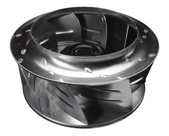
CyberTWO Series VFS-EC Installation, Operation & Maintenance Manual

                           TABLE OF CONTENTS                                                        (Continued)

                       List of Figures                                                               Appendix A - Forms
                                                                                  Checklist for Completed Installation ......................... A-1
Figure 1     Typical Internal Layout - Downflow .......... 1-6                    Periodic General Maintenance
Figure 2     Typical Internal Layout - Upflow ............... 1-7                 Checks and Service Checklist .................................. A-2

Figure 3     Installation Clearance ............................. 2-1
Figure 4     Typical Installation .................................. 2-2                           Appendix B - Glossary
Figure 5     Downflow Configuration                                               Definition of Terms and Acronyms ............................ B-1
             Typical Air Patterns ................................ 2-3
Figure 6     Upflow Configuration
             Typical Air Patterns ................................ 2-4
Figure 7     Optional Floor Stand Installation ............. 2-5
Figure 8     Condensate Pump .................................. 2-9
Figure 9     Sample Nameplate ................................. 2-9
Figure 10 Interconnecting Field Wiring
          Remote Condenser ................................2-11
Figure 11 Interconnecting Field Wiring
          Glycol Systems .................................... 2-12

                                                                      Notice

This document contains information protected by copyright. All rights are reserved. The owner of the equipment for
which this manual is written may photocopy the contents of this manual for internal use only. No part of this docu-
ment may be photocopied, reproduced, or translated into another language for use by anyone other than the owner
of the equipment for which this manual is written without the prior written consent of Stulz Air Technology Systems,
Inc. (SATS).

This document contains confidential and proprietary information of Stulz Air Technology Systems, Inc. Distributing or
photocopying this document for external distribution is in direct violation of U.S. copyright laws and is strictly
prohibited without the express written consent of SATS.

Unpublished — rights reserved under the copyright laws of the United States and of other countries.
Other brands and tradenames are trademarks of their respective owners.

Copyright 2007 by Stulz Air Technology Systems, Inc.
Printed in the United States of America.
All rights reserved.

Stulz Air Technology Systems, Inc.
1572 Tilco Drive
Frederick, MD 21704
USA

ii                                                                                                                                 (© April, 2008)

                                                                Air Technology Systems, Inc.
CyberTWO Series VFS-EC Installation, Operation & Maintenance Manual
1.0 INTRODUCTION The functional modes of operation, in addition to
cooling, are heating, humidification, dehumidification
1.1 General and filtration which provide complete environmental
control of a conditioned space.
Congratulations, the CyberTWO™ floor mounted
precision air conditioning system covered by this There are two air flow pattern configurations, upflow
manual is designed and manufactured by Stulz Air and downflow, and several cabinet sizes based on the
Technology Systems, Inc. (SATS) using the latest, type of system and capacity. Regardless of configura-
state-of-the-art control technology. Recognized as a tion, CyberTWO systems are compact and versatile.
world leader, SATS provides air conditioning systems See the Installation drawing provided with your unit for
with the highest quality craftsmanship using the finest the layout and dimensions of the cabinet.
materials available in the industry. The unit will provide
years of trouble free service if installed and maintained The CyberTWO unit is provided with a main power
in accordance with this manual. Damage to the unit disconnect switch located inside the electric box. The
from improper installation, operation or maintenance is disconnect switch electrically isolates the unit during
not covered by the warranty. routine maintenance. The system incorporates state-
of-the-art component protection with the use of motor
STUDY the instructions contained in this manual. start protectors and circuit breakers.
They must be followed to avoid difficulties. Spare parts
are available from SATS to insure continuous opera- An operating manual for the system controller is
tion. Using substitute parts or bypassing electrical or provided under separate cover. Refer to that manual for
refrigeration components in order to continue operation detailed instructions on operating the system control-
is not recommended and will VOID THE WARRANTY. ler provided with your unit.
Due to technological advancements, components are
The standard controller for the CyberTWO unit is the
subject to change without notice.
C6000 microprocessor, which provides the following
All CyberTWO systems and centrifugal condensers features: input/output monitoring status, full integrated
are designed to be installed indoors, unless otherwise control of heating, cooling, humidification and dehu-
noted on the equipment. Propeller-type condensers, midification; multi-unit control and remote communica-
drycoolers and pump packages are designed for tion with building management systems. The controller
outdoor use. is typically factory mounted on the front hinged access
door of the unit. As an option, the controller may be
1.2 Product Description remotely mounted to a wall or control panel.
CyberTWO systems are designed to be the most
versatile and flexible floor mounted air conditioning
systems in the industry. The unit is available in air
cooled, water cooled and glycol cooled configurations.
The cooling capacity, in BTU/Hr, will depend on the
unit size, which can range from 72,000 to 360,000
BTU/Hr. CyberTWO systems are designed to operate
with either R22 or R407C refrigerant. Refer to the unit
nameplate to identify which refrigerant is used with
your unit.
NOTE
The CyberTWO systems are designed to sup- C6000 Controller
ply air to only one room.
(© April, 2008) 1-1
Air Technology Systems, Inc.CyberTWO Series VFS-EC Installation, Operation & Maintenance Manual
1.3 Product Warranty
SATS offers a two year standard limited warranty as stated on the following pages. Additionally an extended
warranty may be purchased on the unit's compressor. Consult the factory to verify if the extended compressor
warranty was purchased for your system. The extended compressor warranty as stated on the next page will be
sent with your unit and should be retained for future reference.
2-Year Standard Limited Warranty:
Stulz Air Technology Systems, Inc., warrants to the original buyer of its products that the goods
are free from defects in material and workmanship. Stulz Air Technology Systems, Inc.’s
obligation under this warranty is to repair or replace, at its option, free of charge to the customer,
any part or parts which are determined by Stulz Air Technology Systems Inc. to be defective
for a period of 24 months from date of shipment when a completed start-up form has been
submitted to Stulz Air Technology Systems, Inc. within 90 days from shipment. In the event
that a completed start-up form is not received by Stulz Air Technology Systems, Inc. within 90
days from shipment, the company’s obligation will be for a period of 12 months from date of
shipment. Parts repaired or replaced under this warranty are shipped FOB Factory, and
warranted for the balance of the original warranty period or for 90 days from the date of
installation, whichever is greater.
Stulz Air Technology Systems, Inc.’s warranty does not cover failures caused by improper
installation, abuse, misuse, misapplication, improper or lack of maintenance, negligence,
accident, normal deterioration (including wear and tear), or the use of improper parts or improper
repair.
Purchaser’s remedies are limited to replacement or repair of non-conforming materials in
accordance with the written warranty. This warranty does not include costs for transportation,
costs for removal or reinstallation of equipment or labor for repairs or replacement made in the
field.
If any sample was shown to the buyer, such sample was used merely to illustrate the general
type and quality of the product, and not to represent that the equipment would necessarily
conform to the sample.
This is the only warranty given by the seller, and such warranty is only given to buyers for
commercial or industrial purposes. This warranty is not enforceable until the invoice(s) is paid
in full.
THE FOREGOING SHALL CONSTITUTE SATS’S ENTIRE LIABILITY AND YOUR EXCLUSIVE
REMEDY. IN NO EVENT SHALL SATS BE LIABLE FOR ANY DIRECT, INDIRECT, SPECIAL,
INCIDENTAL, CONSEQUENTIAL, OR EXEMPLARY DAMAGES, INCLUDING LOST PROFITS
(EVEN IF ADVISED OF THE POSSIBILITY THEREOF) ARISING IN ANY WAY OUT OF THE
INSTALLATION, USE OR MAINTENANCE OF THE EQUIPMENT. THIS WARRANTY IS IN
LIEU OF ALL OTHER WARRANTIES, EXPRESS OR IMPLIED, INCLUDING WARRANTIES OF
MERCHANTABILITY OR FITNESS FOR A PARTICULAR PURPOSE.
1-2 (© April, 2008)
Air Technology Systems, Inc.CyberTWO Series VFS-EC Installation, Operation & Maintenance Manual
Optional Limited Extended Warranty (5 Years Total)
Stulz Air Technology Systems, Inc., warrants to the original buyer of its product that
the compressor(s) listed below are warranted for parts replacement (not including
labor) for extended period of 4 years from the date of expiration of the standard
equipment warranty.
Stulz Air Technology Systems’ warranty does not cover failures caused by improper
installation, abuse, misuse, misapplication, improper or lack of maintenance, negli-
gence, accident, normal deterioration including normal wear and tear, or the use of
improper parts or improper repair as determined by SATS.
This warranty does not include costs of transportation, cost for removal or reinstallation
of equipment or labor for repairs or replacement made in the field.
The obligation and liability of Stulz Air Technology Systems under this warranty does
not include losses, direct or indirect, for incidental or consequential damages.
Compressor Serial No.: __________________________________
Unit Model No.: __________________________________
Unit Serial No.: __________________________________
Stulz Air Technology Systems Job No.: __________________________________
End User: __________________________________
Date: __________________________________
(© April, 2008) 1-3
Air Technology Systems, Inc.CyberTWO Series VFS-EC Installation, Operation & Maintenance Manual
1.4 Safety
WARNING
1.4.1 General
To prevent personal injury, stay clear of rotating
Stulz Air Technology Systems, Inc. uses NOTES components as automatic controls may start
along with CAUTION and WARNING symbols through- them unexpectedly. Turn off power to the unit
out this manual to draw your attention to important unless you are performing tests that require
operational and safety information. power. With power and controls energized, the
unit could begin operating at any time.
A bold text NOTE marks a short message in the
information to alert you to an important detail. Never operate the unit with any cover, guard, screen
panel, etc. removed unless the instructions specifically
A bold text CAUTION safety alert appears with state otherwise, then do so with extreme caution to
information that is important for protecting your avoid personal injury.
equipment and performance. Be especially careful to
read and follow all cautions that apply to your applica- Never lift any component in excess of 35 pounds
tion. without help. If a lifting device is used to move a unit
ensure it is capable of supporting the unit.
A bold text WARNING safety alert appears with
information that is important for protecting you from When working on electrical equipment, remove all
harm and the equipment from damage. Pay very jewelry, watches, rings, etc.
close attention to all warnings that apply to your
application. Always disconnect the main power supply to the
equipment at the main power disconnect switch before
A safety alert symbol precedes a general WARN- beginning work on the equipment. A lock-out tag-out
procedure should be followed to ensure that power is
ING or CAUTION safety statement.
not inadvertently reconnected.
A safety alert symbol precedes an electrical Never work on electrical equipment unless another
shock hazard WARNING or CAUTION safety state- person who is familiar with the operation and hazards
ment. of the equipment and competent in administering first
aid is nearby.
1.4.2 Safety Summary
All personnel working on or near equipment should be
The following statements are general guidelines familiar with hazards associated with electrical
followed by warnings and cautions applicable maintenance. Safety placards/stickers have been
throughout the manual. placed on the unit to call attention to all personal and
Prior to performing any installation, operation, mainte- equipment damage hazard areas.
nance or troubleshooting procedure read and under- Certain maintenance or cleaning procedures may call
stand all instructions, recommendations and guide- for the use and handling of chemicals, solvents, or
lines contained within this manual. cleansers. Always refer to the manufacturer's Material
Safety Data Sheet (MSDS) prior to using these
WARNING materials. Clean parts in a well-ventilated area. Avoid
inhalation of solvent fumes and prolonged exposure
This equipment should be serviced and repaired
of skin to cleaning solvents. Wash exposed skin
by journeyman, refrigeration mechanic or an air
thoroughly after contact with solvents.
conditioning technician.
1-4 (© April, 2008)
Air Technology Systems, Inc.CyberTWO Series VFS-EC Installation, Operation & Maintenance Manual
WARNING WARNING
This unit employs high voltage equipment with When performing soldering or desoldering op-
rotating components. Exercise extreme care to erations, make certain the refrigeration system
avoid accidents and ensure proper operation. is fully recovered and purged and dry nitrogen
is flowing through the system at the rate of not
WARNING less than 1-2 CFM (.03 - .06 M³/minute).
Hazardous voltage will still be present inside the CAUTION
electric box at the motor start protectors and
circuit breakers, even with the unit turned off at When the air conditioner is in the cooling mode,
the microprocessor controller. To isolate the unit the return air-intake and discharge (supply)
for maintenance, turn off power at the main power must be free of obstructions. Ensure panels are
disconnect switch. Always disconnect main secure and latched into position.
power prior to performing any service or repairs.
CAUTION
WARNING
Do not use cleaning solvents near open flame or
Refrigerant (R22 or R407C) is used with this excessive heat. Wear eye protection when blow-
equipment. Death or serious injury may result if ing solvent from parts. The pressure-wash should
personnel fail to observe proper safety precau- not exceed 30 psig. Solvent solutions should be
tions. Great care must be exercised to prevent disposed of in accordance with local and state
contact of liquid refrigerant or refrigerant gas, dis- regulatory statutes.
charged under pressure, with any part of the
body. The extremely low temperature resulting CAUTION
from the rapid expansion of liquid refrigerant or
pressurized gas can cause sudden and irrevers- The unit must be kept in its normal installed po-
ible tissue damage. sition. If the unit is not kept level and vertical,
damage to the unit's compressors will result.
As a minimum, all personnel should wear ther-
mal protective gloves and face-shield/goggles
when working with refrigerant. Application of ex-
cessive heat to any component will cause ex-
treme pressure and may result in a rupture.
Exposure of refrigerant to an open flame or a
very hot surface will cause a chemical reaction
that will form carbonyl chloride (hydrochloric/hy-
drofluoric acid); a highly poisonous and corro-
sive gas commonly referred to as PHOSGENE.
In its natural state, refrigerant is a colorless, odor-
less vapor with no toxic characteristics. It is
heavier than air and will disperse rapidly in a
well-ventilated area. In an unventilated area, it
presents a danger as a suffocant.
Always refer to the manufacturer's MSDS pro-
vided with the unit.
(© April, 2008) 1-5
Air Technology Systems, Inc.CyberTWO Series VFS-EC Installation, Operation & Maintenance Manual
1.5 General Design NOTE
Customer specified non standard features or de-
The CyberTWO VFS-EC unit is housed in a steel frame sign variations may not be described in this
type cabinet and is rated for indoor use. The exterior of manual. Refer to the installation and/or electri-
the cabinet is coated with a powder coat finish to cal drawings supplied with your unit for details
protect against corrosion. Hinged doors are located in on additional feature(s). In some cases, an ad-
the front of the cabinet for easy access to all compo- dendum to this manual may also be included to
nents. Operator controls are conveniently located on the further describe the feature(s).
front of the cabinet.
Figure 1 depicts a sample internal layout of a downflow unit and identifies the major components. Location of the
major components vary depending on VFS model number and options purchased.
NOTE: CABINET DOORS AND SIDE ACCESS PANEL REMOVED TO SHOW INTERNAL PARTS
FILTER RACK T/H SENSOR
FILTER RACKS
SMOKE
DETECTOR
FIRESTAT
FIRESTAT
ELECTRIC
BOX
HUMIDIFIER
MAIN POWER SERVICE
COILS DISCONNECT SWITCH
HEAT EXCHANGERS
ELECTRIC
REHEAT COMPRESSORS
FIN TUBE
CONDENSATE
PUMP
EC FANS
LEFT SIDE FRONT
Figure 1 - Typical Internal Layout - Downflow
1-6 (© April, 2008)
Air Technology Systems, Inc.CyberTWO Series VFS-EC Installation, Operation & Maintenance Manual
Figure 2 depicts a sample internal layout of an upflow unit and identifies the major components. Location of the
major components vary depending on VFS model number and options purchased.
NOTE: CABINET DOORS AND SIDE ACCESS PANEL REMOVED TO SHOW INTERNAL PARTS
ELECTRIC REHEAT
FIN TUBE
HUMIDIFIER
COILS
ELECTRIC
BOX
MAIN POWER SERVICE
DISCONNECT SWITCH
FILTER HEAT EXCHANGERS
COMPRESSORS
CONDENSATE
PUMP
EC FANS FIRESTAT T/H SENSOR
SMOKE
LEFT SIDE DETECTOR
FRONT
Figure 2 - Typical Internal Layout - Upflow
1.5.1 Electric Box Access The electric box cover is safety interlocked with the
The electrical components are protected in an enclo- main power service disconnect switch, preventing the
sure located in the cabinet behind the hinged access cover from being removed when the switch is in the
door with the system controller. Before opening the “On” position. The main power service disconnect
access door, turn the “On/Off” switch beneath system switch must be turned “Off” to gain access to the
controller to the “Off” position. This removes power components within the electric box.
from the system controller and shuts the unit off. The main power service disconnect switch may be
used to turn the unit off for emergency shutdown or
WARNING during routine maintenance. The handle of the switch
may be locked in the “Off” position to prevent unin-
Hazardous voltage will still be present inside the tended operation.
cabinet, even with the unit turned off at the sys-
tem controller. To isolate the unit for maintenance,
turn off power at the main power service discon-
WARNING
nect switch on the electric box cover. This unit employs high voltage equipment with
rotating components. Exercise extreme care to
WARNING avoid accidents. Always keep hands, clothing
and tools clear of the EC Fan blades when power
With power and controls energized, the unit could is “On”.
begin operating at any time. To prevent personal
injury, stay clear of rotating components as au-
tomatic controls may start them unexpectedly.
(© April, 2008) 1-7
Air Technology Systems, Inc.CyberTWO Series VFS-EC Installation, Operation & Maintenance Manual
1.5.2 Circuit Breakers / Motor Start Protectors loose for field installation. Refer to the electrical
drawing supplied with your unit for details specific to
Individual overload protection is provided by circuit your system.
breaker(s) and motor start protectors. These switches
must be manually reset once the overload condition is 1.5.6 Heaters (Optional)
cleared.
The precision A/C unit incorporates heaters for reheat-
1.5.3 Coil(s) ing the supply air as required to offset the sensible
The cooling and optional hot water reheating coils are cooling of the system during the dehumidification cycle
aluminum finned/copper tube construction. The coils are and for the automatic heating mode. As a standard,
leak tested and cleaned before installation by the factory. electric resistance heating elements are factory
installed in the supply airstream to heat the supply air.
1.5.4 EC Fan(s)
As an option, hot water reheat may be selected. A hot
The unit is equipped with high efficiency, Electronically water heating coil is factory installed in the supply air
Commutated (EC) fan(s). EC Fans utilize a brushless stream to heat the supply air. A valve is provided to
motor equipped with permanent magnets and perma- control the flow of hot water through the coil to main-
nently lubricated ball bearing. The Fan impellers are tain the correct reheat temperature.
backward curved and attached to the rotor casing. The
fan is balanced and aerodynamically optimized to 1.6 Optional Equipment
minimize vibration.
1.6.1 Humidifier
The fan does not utilize drive belts. The fan speed is
variable via a 0 to 10 VDC signal from the system CyberTWO VFS-EC systems may utilize an optional
controller. The fan motor is equipped with integral electrode, steam humidifier. The humidifier is factory
electronics and does not require the addition of installed inside the air conditioner and includes fill and
secondary electronics such as thermal protection, drain valves and associated piping. Operation of the
inverters or filters. The fan will not produce AC inverter humidifier’s fill and drain cycles is based on water
whine. conductivity and is maintained by the humidifier
controller. An operating manual for the humidifier is
EC fans feature an integrated monitoring function to
provided under separate cover. Refer to that manual for
protect the motor and electronics against damage from
detailed information on operation of the humidifier.
jamming, phase loss or overheating. If any of the
following failure conditions occur, the motor automati- 1.6.2 Condensate Pump
cally stops and an alarm is signaled:
a. Locked rotor1 An optional factory installed condensate pump may be
b. Low main supply voltage1 provided. The pump automatically eliminates conden-
c. Loss of a phase1 sate and humidifier flush water (if applicable) from the
d. Over-heating of electronics2 drain pan. An internal overflow safety switch is wired to
e. Over-heating of motor2 the system controller to automatically shut down the
1
Upon correction of these failure conditions, the precision A/C system should an overflow occur.
motor will automatically reset.
2
1.6.3 Smoke Detector
Upon correction of these failure conditions, the
motor must be manually reset by turning off power Optionally mounted in the return air stream, a photo-
for 20 seconds. electric smoke detector is used to sense the presence
of smoke and signal the controller when a smoke
1.5.5 Temperature/Humidity Sensor
alarm condition exists.
As a standard, a temperature/humidity (T/H) sensor is
factory mounted in the return air stream for room air 1.6.4 Firestat
control. The (T/H) sensor monitors the return air
Optionally mounted in the return air stream, a fire
conditions and provides input signal(s) to the system
detector senses high retun air temperature and signals
controller to manage the operation of the A/C unit
the controller when a fire alarm condition exists.
consistent with the setpoints entered in the system
controller. As an option, sensor(s) may be shipped
1-8 (© April, 2008)
Air Technology Systems, Inc.CyberTWO Series VFS-EC Installation, Operation & Maintenance Manual
2.0 INSTALLATION NOTE
Working clearance requirements need to be es-
2.1 Receiving the Equipment tablished prior to mounting the unit. Refer to lo-
Your CyberTWO system has been tested and in- cal and national electrical codes.
spected prior to shipment. To ensure that your equip-
ment has been received in excellent condition, make a
visual inspection of the equipment immediately upon
delivery. Carefully remove the shipping container and
all protective packaging. Remove the access panels
and thoroughly inspect the unit interior for any signs of
transit-incurred damage. If there is shipping damage, it
must be noted on the freight carrier's delivery forms
BEFORE signing for the equipment. Any freight claims
MUST be done through the freight carrier. SATS ships
all equipment FOB. SATS can assist in the claim
filing process with the freight carrier. Should any
damage be present, notify the SATS Product Support 30"
Group prior to attempting any repairs. Refer to section (MINIMUM SIDE
CLEARANCE)
five of this manual for instructions. 40"
(MINIMUM FRONT
CLEARANCE)
A Data Package has been sent with your unit. It 30"
(MINIMUM SIDE
contains this manual, a supplemental microprocessor CLEARANCE)
controller manual, system drawings, applicable
MSDS’s, other component manuals, warranty registra-
tion and other applicable instructions based on the Figure 3 - Installation Clearance
configuration and options of your unit. The data
package has been placed in your unit in a clear plastic To minimize the effects of the environment surrounding
envelope. These documents need to be retained with the conditioned space, certain steps must be taken.
the unit for future reference. This is especially true for critical/precision room
preparation (computer rooms/labs) requiring close
NOTE tolerance control of temperature and humidity. The
conditioned space should be well insulated and
Items that have been shipped loose, such as con-
include a vapor barrier. The installer should ensure that
trollers, temperature/humidity sensors, water
the proper insulation rating is used based on the
detectors, etc., are shipped inside the air condi-
design of the space, which was the basis for the
tioner unless specified otherwise by the customer.
system selected. The following chart is a recom-
Unpack and store these items in a safe place
mended minimum R-value (thermal resistance) to
unless you are using them immediately.
ensure optimum equipment operation.
2.2 Site Preparation
STRUCTURE R-VALUE
CyberTWO systems are designed with easy service
access in mind. Hinged doors are located on the front Ceiling R-38
of the unit and removable access panels are provided Wall R-21
on each side. The number of doors may vary depend- Floor R-19
ing on size and configuration. Each unit has an Door R-5
electrical box inside the cabinet with a removable
panel for accessing the electrical components. In order
to have full service access through the front of unit, no The vapor barrier is the single most important require-
permanent obstructions can be placed within 40 ment for maintaining environmental control in the
inches of the front of unit. Side access panels require conditioned space. The vapor barrier in the ceiling and
a minimum of 30 inches of clearance to remove and walls can be a polyethylene film. Concrete walls and
replace components (see Figure 3). floors should be painted with a rubber or plastic based
(© April, 2008) 2-1
Air Technology Systems, Inc.CyberTWO Series VFS-EC Installation, Operation & Maintenance Manual
paint. Doors and windows should be properly sealed 2.4 Mounting/Placement
and a door sweep used to minimize leakage. Outside
or fresh air should be kept to a minimum (as it adds to CyberTWO systems that are not ducted are designed
the cooling, heating, dehumidification and humidifying to be located in the conditioned space. Ducted units
loads), while maintaining the requirement of the Indoor may be either inside or outside the conditioned space
Air Quality (IAQ) standard. Lack of these steps can but are designed to supply air to only one room.
cause erratic operation, unstable room control and CyberTWO series systems are 100% front accessible,
excessive maintenance costs. which allows the units to be placed in a corner or
between cabinetry. It is recommended to position the
2.3 Rigging unit to obtain optimum air circulation.
CyberTWO systems are designed to be kept in the NOTE
vertical position. Move the unit with a suitable device
Placement of the floor registers is important. If
such as a forklift, pallet jack or roller bar and dollies.
they are too close to the unit, the supply air will
For reference, a weight table is provided on the
be recirculated back to the unit before it has
installation drawing. Units are shipped on a skid to
circulated throughout the space.
facilitate moving prior to installation. Units should
always be stored indoors in a dry location prior to See Figure 4. The unit is designed to be located
installation. directly on top of the floor (typically upflow) or on a
raised floor (typically downflow).
CAUTION
Units must be kept level and in the vertical posi- CAUTION
tion when lifting to prevent damage to the unit. Ensure the mounting surface is capable of sup-
porting the equipment. Before mounting the unit,
refer to the weight provided on the installation
drawing. On some raised floor installations a floor
stand is required, depending on the load capac-
ity of the existing raised floor.
HINGED
DOOR
C6000 SERIES
CONTROLLER
ON/OFF
SWITCH
FLOOR STAND
(OPTIONAL)
UPFLOW DOWNFLOW
CONFIGURATION CONFIGURATION
Figure 4 - Typical Installation
2-2 (© April, 2008)
Air Technology Systems, Inc.CyberTWO Series VFS-EC Installation, Operation & Maintenance Manual
2.4.1 Precision A/C Unit Secure the condenser/condensing unit to prevent the
system from moving during operation. It is recom-
CyberTWO systems use a frame and panel construc- mended that the remote condenser be mounted with
tion for unit rigidity and full service accessibility while field supplied vibration mounts to reduce vibration
the unit is mounted in place. transmitted to the mounting surface.
If a floor stand is selected for downflow units, refer to
the installation drawing provided and cut out the raised
2.5 Air Distribution Connection
floor to match the unit’s overall base dimension. If a 2.5.1 Downflow Configuration Air Patterns
floor stand is not selected, use the installation drawing
and cut out the raised floor to match the discharge In a downflow configured unit, the conditioned supply
opening for the blowers and cut out the holes required air discharge is through the bottom of the unit into the
for piping and wiring through the raised floor. raised floor. There are two basic air patterns; top free
return and top ducted return (see Figure 5).
NOTE
If ductwork is to be used, always consult your state
The equipment must be level to operate properly. and local codes when determining ducting require-
ments. The duct system should be designed to allow
2.4.2 Outdoor Equipment
the air to move with as little resistance as possible.
Install remote condensers in a secure location where
the unit cannot be tampered with and the main power The connection of ductwork to the unit is typically
circuit breaker cannot be inadvertently turned off. made to a one-inch collar provided at the top of the
Locate the remote condenser where the fan is not unit (refer to the installation drawing provided with the
likely to draw dirt and debris into the coil fins. There unit). The connection of the duct to the unit may be
should be at least 24 inches of clearance around the made with either pop rivets or self-tapping screws.
condenser to ensure adequate airflow to the coil.
RETURN
AIR INLET
RETURN
AIR INLET
SUPPLY SUPPLY
AIR OUTLET AIR OUTLET
TOP FREE RETURN TOP DUCTED RETURN
Figure 5 - Downflow Configuration Typical Air Patterns
(© April, 2008) 2-3
Air Technology Systems, Inc.CyberTWO Series VFS-EC Installation, Operation & Maintenance Manual
2.5.2 Upflow Configuration Air Patterns
In an upflow configured unit, the conditioned supply air has two methods of discharge: ducted or through a 2 or 3-
way grilled plenum box. The return air pattern is front free return. (See Figure 6.)
The supply air outlet is provided with a flange for connection of ductwork (refer to the installation drawing provided
with the unit). The connection of ductwork to the unit may be made with either pop rivets or self-tapping screws.
If ductwork is to be used, always consult your state and local codes when determining ducting requirements. The
duct system should be designed to allow the air to move with as little resistance as possible.
FRONT FREE RETURN
SUPPLY OPTIONAL
AIR OUTLET PLENUM BOX
SUPPLY
AIR OUTLET
DUCT
RETURN AIR RETURN
INLET AIR INLET
TOP DUCTED DISCHARGE TOP DISHARGE WITH 2-3 WAY PLENUM BOX
Figure 6 - Upflow Configuration Typical Air Patterns
2-4 (© April, 2008)
Air Technology Systems, Inc.CyberTWO Series VFS-EC Installation, Operation & Maintenance Manual
2.6 Optional Equipment (Field Installed)
2.6.1 Floor Stand
Install the floor stand directly on the sub-floor, ensuring the side with the "FRONT" label is facing the same direction
as the front of the precision A/C unit (see Figure 7). Refer to the floor stand assembly drawing for the dimensions
required to cut the opening in the raised floor. The optional floor stand is designed with adjustable feet on all the legs,
allowing for leveling and overall height adjustment. Refer to the floor stand assembly drawing for minimum and
maximum height adjustability of your floor stand. To adjust the height, first loosen the middle nuts on each leg. Next,
turn the top hex nuts to raise or lower the floor stand. Once the floor stand is level and even with the raised floor, lock
all feet in place by tightening the middle hex nuts against the top hex nuts.
TURNING VANES
(OPTIONAL)
"FRONT" LABEL
FLOOR STAND
LEG
TOP HEX NUT THREADED ROD
MIDDLE HEX NUT
ISOLATION PAD
Figure 7 - Optional Floor Stand Installation
(© April, 2008) 2-5
Air Technology Systems, Inc.CyberTWO Series VFS-EC Installation, Operation & Maintenance Manual
2.6.2 Remote Display 2.6.4 Remote Water Detector
The C6000 Microprocessor is the standard controller The remote water detector is normally placed on the
supplied with CyberTWO systems. As an option the subfloor or in a field supplied auxiliary drain pan located
control panel may be remote mounted. For mounting beneath the unit. SATS provides 2 types of water
and wiring instructions, refer to the system drawings detectors:
and the supplemental manual sent in the data pack- Spot type water detector-
age with your unit.
Remove the protective cover and connect two control
wires to the terminals on the base
2.6.3 Remote Temperature/Humidity Sensor
(terminal lugs are provided). Replace the
The remote temperature/humidity (T/H) sensor must be cover and place the water detector(s) on
located so that it will properly sense the temperature/ the floor with the metal electrodes
humidity conditions to be controlled. The T/H sensor facing down. When water is present,
should not be mounted near a doorway or an area current will flow between the electrodes. The base is
where it would be exposed to direct sunlight. Follow the provided with a mounting hole in the center which may
steps below to mount the sensor. For unit wiring details, be used to secure the water detector in place.
refer to Section 2.8, Utility Connections. NOTE
Do not place the spot type water detector on
COVER
SCREW an electrically conductive surface.
Cable type water detector-
Lay the cable water detector
flat across the subfloor
where water could collect.
When water is present,
Temperature /Humidity Sensor current will flow between the
1. Using a flat head screwdriver, remove the cover two wires. A two conductor wire harness is provided
plate from the base of the sensor. with a quick connect fitting on the end. The harness
mates to the fitting on the water detector and connects
2. Place the base temporarily over the wire hole it to the control board inside the electric box.
opening in the wall. Level the base and mark the
mounting hole locations through the two slots.
3. Drill the mounting holes and insert the provided
wall anchors.
4. Run the wires coming out of the wall through the
opening in the base, then secure the base with the
screws provided.
5. Make the wiring connections. See Section 2.8
Utility Connections and refer to the wiring diagram
supplied with your unit.
6. Replace the cover plate on the base.
CAUTION
Take care not damage the exposed tempera-
ture/humidity sensors on the PC board while
screwing in the cover fastening screw. The sen-
sors can be damaged if handled improperly.
2-6 (© April, 2008)
Air Technology Systems, Inc.CyberTWO Series VFS-EC Installation, Operation & Maintenance Manual
2.7 Piping Connections Refrigerant lines for split systems must be sized
according to the piping distance between the evapora-
For downflow VFS models, piping is to be routed tor and the condenser/condensing unit. Each valve,
through the bottom of the cabinet. For upflow models, fitting and bend in the refrigerant line must be consid-
the piping is to be routed through the top of the cabinet. ered in this calculation. Refer to the following chart
Once the piping is connected to the A/C unit, install 2- provided for determining the standard equivalent
piece, pipe penetration plates (shipped loose) around lengths, in feet, of straight pipe.
the piping to stop air bypass. Mounting holes are
predrilled in the plates. Self drilling screws are provided
to attach the plates to the A/C cabinet. Equivalent Length (ft) of Straight Pipe
OD (In.) Globe Angle 90º 45º Tee Tee
2.7.1 Refrigerant Line Size Valve Valve Elbow Elbow Line Branch
2.7.1.1 Self-Contained Systems 1/2 9.0 5.0 0.9 0.4 0.6 2.0
5/8 12 6.0 1.0 0.5 0.8 2.5
No refrigerant connections are required for self-
contained water or glycol cooled systems (Models 7/8 15 8.0 1.5 0.7 1.0 3.5
VFS-[ ]-DW/DG-[ ]). 1-1/8 22 12 1.8 0.9 1.5 4.5
1-3/8 28 15 2.4 1.2 1.8 6.0
2.7.1.2 Split Systems
1-5/8 35 17 2.8 1.4 2.0 7.0
Split air-cooled systems with a remote condenser will
require field refrigeration piping. All split systems are 2-1/8 45 22 3.9 1.8 3.0 10
shipped with a dry nitrogen charge of 50 psig. 2-5/8 51 26 4.6 2.2 3.5 12
3-1/8 65 34 5.5 2.7 4.5 15
Split systems coupled with a remote condenser will
require a copper discharge and copper liquid line. 3-5/8 80 40 6.5 3.0 5.0 17
All refrigeration piping should be installed with high
temperature soldered joints. Use standard refrigeration When installing remote condenser(s) above the
practices for piping supports, leak testing, dehydration evaporator, the discharge line should include a shallow
and charging of the refrigeration circuits. The refrigera- P-trap at the evaporator. The highest point in the
tion piping should be isolated from the building by the discharge line should be above the condenser coil. An
use of vibration isolating supports. To prevent tube inverted trap is required on the discharge line of the
damage when sealing openings in walls and to reduce remote condenser to help prevent oil and liquid refriger-
vibration transmission, use a soft flexible material to ant from flooding back to the compressor.
pack around the tubes. Oil traps must be included every 20 feet in the vertical
Clear all pipe connections of debris and prepare the risers and the refrigerant lines must be sloped ¼ inch
connections for soldering. Use only "L" or "K" grade for every 10 feet in the horizontal lines to ensure proper
refrigerant copper piping. Be careful not to allow oil return to the compressor.
solder/piping debris to get inside refrigerant lines. Refer to the following refrigerant line size charts for
Silver solder containing a minimum of 15% silver is recommended line sizing.
recommended. Dry nitrogen should be flowing through
the tubing while soldering at a rate of not less than 1-2
CFM (.03 - .06 M3/minute).
(© April, 2008) 2-7
Air Technology Systems, Inc.CyberTWO Series VFS-EC Installation, Operation & Maintenance Manual
NOTE 2.7.2 Water/Glycol
In the following charts, the line sizes represent Piping connections for water/glycol condensers are
the sizing for individual refrigeration circuits. sweat connections. Field piping may not necessarily
CyberTWO units have two separate pairs of re- be the same size as the unit connection. Piping
frigeration lines. (One per compressor.) should be sized to match the required system pres-
sure drop and pump capacity, and may require a
Recommended Liquid Line Sizes reducing fitting to match the connection size on the air
conditioner. Glycol cooled systems with low entering
(For R22 or R407C Refrigerant)
fluid temperatures should have insulated piping.
Model No./ Receiver to Evaporator (Equivalent Ft.)*
Total Unit 50' 100' 150' The recommended ethylene glycol solution ratio is
Capacity or less or less or less
40% glycol to 60% water. (SATS recommends
072 / 72,000 1/2 1/2 1/2 Dowtherm SR1 manufactured by Dow Chemical Co.)
Use only ethylene glycol with inhibitors for corrosion
096 / 96,000 1/2 5/8 5/8
protection.
120 / 120,000 1/2 5/8 5/8
180 / 180,000 5/8 7/8 7/8
WARNING
240 / 240,000 7/8 7/8 7/8 Glycol is hazardous. Consult the manufacturer's
MSDS for detailed safety information.
312 / 312,000 7/8 7/8 7/8
360 / 360,000 7/8 7/8 1 1/8 CAUTION
*Equivalent Ft. accounts for the linear pipe length as well as When installing and filling the water/glycol loop, all
equivalent length of Valves, Elbows & Tee’s as shown in the air must be bled from the piping system and the
previous chart. piping system must be cleaned prior to operating
the system. Failure to do so will result in equip-
Recommended Discharge Line Sizes ment problems.
(For R22 or R407C Refrigerant) 2.7.3 Condensate Drain
Model No./ Equivalent Length Ft.*
Total Unit 50' 100' 150' 2.7.3.1 Gravity Drain
Capacity or less or less or less
A 7/8 inch OD copper (sweat type) line is provided to
072 / 72,000 7/8 7/8 7/8
drain the condensate pan. An “S” trap is installed at
096 / 96,000 7/8 7/8 7/8 the end of piping for the installer to connect a 7/8 inch
ID drain line to remove water from the cabinet. This line
120 / 120,000 7/8 1-1/8 1-1/8
also drains the humidifier.
180 / 180,000 1-1/8 1-1/8 1-3/8
NOTE
240 / 240,000 1-1/8 1-3/8 1-3/8
The humidifier drains (hot) water into the
312 / 312,000 1-1/8 1-3/8 1-3/8 condensate drain during normal operation.
360 / 360,000 1 3/8 1 3/8 1 5/8 The drain line must be located so it will not be ex-
posed to freezing temperatures. The diameter of the
NOTE drain line should be the full size of the connection.
Vertical runs are based on a total rise of 30 equivalent
feet. For longer sizes, individual calculations must be NOTE
made. Sizes assume the use of single risers; double Pour some water into the condensate drain pans
risers may be necessary. prior to start-up. This fills the trap and prevents
air from being drawn up the drain lines.
Consult the Copeland applications data guide for more
detailed information regarding refrigerant line traps and
line sizing.
2-8 (© April, 2008)
Air Technology Systems, Inc.CyberTWO Series VFS-EC Installation, Operation & Maintenance Manual
2.7.3.2 Condensate Pump 2.8 Utility Connections
An optional condensate pump is normally factory 2.8.1 Main Power
installed. The drain connection may be 1/2” ID vinyl
tubing or 1/2” OD copper sweat connection. The CyberTWO product offering is available in 208,
460 and 575 volt three-phase configurations. It is
imperative that the unit nameplate be examined to
determine the operating voltage, frequency and phase
INLET 7/8" OD
of the system (see Figure 9). The nameplate also
OUTLET 1/2" OD
provides the full load amps (FLA), the current the unit
will draw under full design load, the minimum circuit
ampacity (MCA) for wire sizing, and the maximum
fuse or HACR (Heating, Air Conditioning, Refrigeration)
SEE NOTE 2
2.00 breaker size (MAX FUSE/CKT BKR) for circuit protec-
SEE NOTE 1
tion. The unit's nameplate is located inside the cabinet
within the electrical box.
NOTES:
1. MIMIMUM HEIGHT IN INCHES.
2. P-TRAP MUST BE LOCATED IN THE INLET SIDE OF PUMP WHEN FIELD INSTALLED.
Figure 8 - Condensate Pump
If an optional field installed condensate pump is used,
a p-trap must be installed to allow proper condensate
drainage (see Figure 8). The height of the trap must be
a minimum of 2 inches on standard systems to ensure
proper water drainage. The condensate pump dis-
charge line should be 1/2 inch OD (maximum) copper
pipe to prevent excessive back flow to the condensate
pump.
2.7.4 Humidifier
CyberTWO systems utilize an electrode steam
humidifier. The humidifier empties into the condensate
drain line during the flush/drain cycle. A water supply
line must be connected to the copper tubing connec-
tion supplied by the factory. Refer to the installation
drawing provided with your unit for the size and
location of the connectrion. The humidifier requires
normal tap water as the water supply. If the supply
water is high in particulate, an external filter may be
needed.
CAUTION
Do not use demineralized water.
Refer to the humidifier operator’s manual, supplied
with the equipment, for complete manufacturer’s
information on the humidifier and the supply water
recommendations.
Figure 9 - Sample Nameplate
(© April, 2008) 2-9
Air Technology Systems, Inc.CyberTWO Series VFS-EC Installation, Operation & Maintenance Manual
NOTE
CAUTION
If the nameplate states MAX FUSE/CKT BKR,
it is required to use fuses or a HACR type cir- Improper wire connections will result in the re-
cuit breaker to protect the system. Other pro- verse rotation of the fans/blower motors and com-
tection devices are not allowed based upon the pressor (if applicable) and may eventually result
product listing. in damage to the scroll compressor. To correct
this problem, exchange any two of the incoming
The unit is provided with terminals for all required field- main power wires at the main power disconnect
wiring. Refer to the electrical schematic supplied with switch. Do NOT rewire the unit's individual com-
the unit for all power and control field-wiring. It is ponents.
important to identify the options that were purchased
with the unit in order to confirm which field connections Prior to unit operation, an adequate unit-to-earth
are required. ground must be connected to the unit.
2.8.2 Controls
WARNING
Stulz Air Technology Systems offers a wide range of
Verify power is turned off before making connec- control features to solve your air conditioning control/
tions to the equipment. alarm requirements. The C6000 Microprocessor is the
standard controller for the CyberTWO system. If it is
NOTE mounted on the unit (standard), no utility connection is
All wiring must conform to local and national elec- required. As an option the display may be remote
trical code requirements. Use of copper conduc- mounted. A six-conductor cable harness is provided for
tors only is required. Wiring terminations may interconnect wiring. Refer to Figures 10 and 11and the
become loose during transit of the equipment; electrical drawing supplied with your unit for details on
therefore, it is required to verify that all wiring interconnecting the field wiring.
terminations are secure.
2.8.3 Optional Equipment
It is important to verify that the main power supply NOTE
coincides with the voltage, phase and frequency
information specified on the system nameplate. The All wiring must be provided in accordance with
supply voltage measured at the unit must be within local and national electrical code requirements.
±10% of the voltage specified on the system name-
plate. 2.8.3.1 Remote Temperature/Humidity Sensor
A manual fused disconnect switch or HACR type The remote temperature/humidity sensor requires a
circuit breaker must be installed per local and national three conductor shielded cable with the shield being
electrical codes for service of equipment. Do not terminated at the unit electric box. Both the electric
mount a customer supplied manual fused disconnect box and the sensor include a terminal strip with box
switch or HACR type circuit breaker to the surface of type lugs for wire connections. Refer to the electrical
the unit. schematic supplied with your unit for the number of
conductors required and for the appropriate wire
Each unit is provided with a main power and control terminations.
pilot hole for connection of the field-wiring conduit.
These pilot holes are located in the floor of the cabinet. 2.8.3.2 Remote Water Detector
A label stating "MAIN POWER INPUT" is in close
proximity. See the installation drawing provided with Each remote water detector used will require two
your unit for pilot hole locations. The main power wires conductors to be wired to the control terminal board
shall be terminated at the line side of the main power within the unit electrical box. The wire insulation must
disconnect switch, located within the electric box. A be rated at 600V. Refer to the electrical schematic
separate equipment ground lug is provided within the supplied with your unit for proper wire terminations.
electrical box for termination of the earth ground wire.
2-10 (© April, 2008)
Air Technology Systems, Inc.CyberTWO Series VFS-EC Installation, Operation & Maintenance Manual
2.8.4 Interconnecting Field Wiring 2.8.4.1 Air Cooled Split Systems With Remote
Condenser
The following system interconnecting field wiring
sections detail the number of conductors required for a See Figure 10. Systems equipped with a remote
typical system. Additional control conductors may be condenser will require field wiring between the A/C
required depending on the options purchased with the system and the remote condenser. Refer to the
equipment. Refer to the supplied electrical schematic electrical schematic supplied with your unit and the
to determine the total number of interconnecting wiring diagram supplied with the condenser (typically
conductors required for your system. It is important to located in the condenser electric box).
note that the control transformer(s) supplied with the
equipment have been sized and selected based upon The installer must provide main power wiring to the
the expected loads for each system. main power distribution block located within the
remote condenser control box. A separate equipment
ground lug is provided within the electrical box for
CAUTION termination of the earth ground wire.
Do not connect any additional loads to the sys-
tem control transformers. Connecting additional The installer must also wire control conductors from
loads to the factory supplied control transformer the terminal board within the A/C unit to the control
may result in overloading of the transformer. terminal board within the remote condenser control
box. Refer to the electrical schematic for the correct
NOTE number of field wires needed and for appropriate wire
All wiring must be provided in accordance with terminations required for your specific system.
local and national electrical code requirements.
SEE NOTE 3
4 CONDUCTOR NON-
SHIELDED CABLE
2 CONDUCTOR
SHIELDED CABLE
MAIN POWER SUPPLY C6000
208-575V/3PH/60Hz
3 CONDUCTOR
SHIELDED CABLE
REMOTE TEMPERATURE/
INTERCONNECTING FIELD HUMIDITY SENSOR
WIRING (TO BE INSTALLED
IN ACCORDANCE WITH
NFPA 70, N.E.C.)
L1
L2
MAIN POWER SUPPLY
L3
208-575V/3PH/60Hz
24VAC
MODEL VFS-360-DAR SHOWN FOR REFERENCE
AIR COOLED CONDENSER
NOTES:
1. PHANTOM WIRES ( ) NOT APPLICABLE FOR SINGLE PHASE POWER SUPPLIES.
2. NUMBER OF CONDUCTORS VARY DEPENDING ON OPTIONS PROVIDED. INTERCONNECTING FIELD WIRING
3. OPTIONAL REMOTE MOUNTED DEVICES. (TO BE INSTALLED IN ACCORDANCE
WITH NFPA 70, N.E.C.)
SEE NOTE 1 & 2
Figure 10 - Interconnecting Field Wiring Remote Condenser
(© April, 2008) 2-11
Air Technology Systems, Inc.You can also read