COMe-bCL6 - USER GUIDE - Kontron
←
→
Page content transcription
If your browser does not render page correctly, please read the page content below
USER GUIDE
COMe-bCL6
User Guide Rev 1.99
Doc. ID: 1062-1415
www.kontron.com // 1
COMe-bCL6 - User Guide Rev 1.99

                  This page has been intentionally left blank

www.kontron.com                                                                            // 2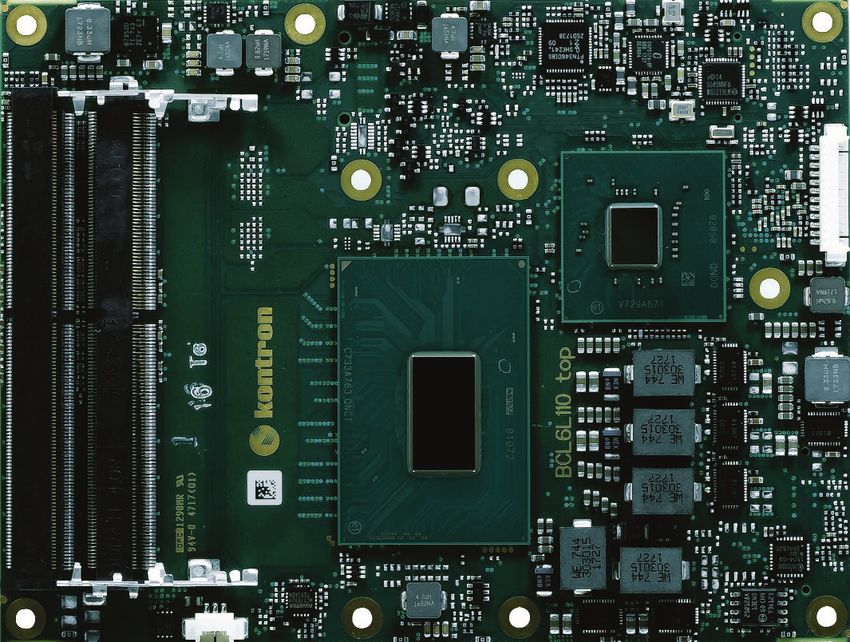
COMe-bCL6 - User Guide Rev 1.99 COME-BCL6 USER GUIDE Disclaimer Kontron would like to point out that the information contained in this user guide may be subject to alteration, particularly as a result of the constant upgrading of Kontron products. This document does not entail any guarantee on the part of Kontron with respect to technical processes described in the user guide or any product characteristics set out in the user guide. Kontron assumes no responsibility or liability for the use of the described product(s), conveys no license or title under any patent, copyright or mask work rights to these products and makes no representations or warranties that these products are free from patent, copyright or mask work right infringement unless otherwise specified. Applications that are described in this user guide are for illustration purposes only. Kontron makes no representation or warranty that such application will be suitable for the specified use without further testing or modification. Kontron expressly informs the user that this user guide only contains a general description of processes and instructions which may not be applicable in every individual case. In cases of doubt, please contact Kontron. This user guide is protected by copyright. All rights are reserved by Kontron. No part of this document may be reproduced, transmitted, transcribed, stored in a retrieval system, or translated into any language or computer language, in any form or by any means (electronic, mechanical, photocopying, recording, or otherwise), without the express written permission of Kontron. Kontron points out that the information contained in this user guide is constantly being updated in line with the technical alterations and improvements made by Kontron to the products and thus this user guide only reflects the technical status of the products by Kontron at the time of publishing. Brand and product names are trademarks or registered trademarks of their respective owners. ©2021 by Kontron Europe GmbH Kontron Europe GmbH Gutenbergstraße 2 85737 Ismaning, Germany www.kontron.com www.kontron.com // 3
COMe-bCL6 - User Guide Rev 1.99

Intended Use
THIS DEVICE AND ASSOCIATED SOFTWARE ARE NOT DESIGNED, MANUFACTURED OR INTENDED FOR USE
OR RESALE FOR THE OPERATION OF NUCLEAR FACILITIES, THE NAVIGATION, CONTROL OR
COMMUNICATION SYSTEMS FOR AIRCRAFT OR OTHER TRANSPORTATION, AIR TRAFFIC CONTROL, LIFE
SUPPORT OR LIFE SUSTAINING APPLICATIONS, WEAPONS SYSTEMS, OR ANY OTHER APPLICATION IN A
HAZARDOUS ENVIRONMENT, OR REQUIRING FAIL-SAFE PERFORMANCE, OR IN WHICH THE FAILURE OF
PRODUCTS COULD LEAD DIRECTLY TO DEATH, PERSONAL INJURY, OR SEVERE PHYSICAL OR
ENVIRONMENTAL DAMAGE (COLLECTIVELY, "HIGH RISK APPLICATIONS").
You understand and agree that your use of Kontron devices as a component in High Risk Applications is entirely at
your risk. To minimize the risks associated with your products and applications, you should provide adequate design
and operating safeguards. You are solely responsible for compliance with all legal, regulatory, safety, and security
related requirements concerning your products. You are responsible to ensure that your systems (and any Kontron
hardware or software components incorporated in your systems) meet all applicable requirements. Unless otherwise
stated in the product documentation, the Kontron device is not provided with error-tolerance capabilities and cannot
therefore be deemed as being engineered, manufactured or setup to be compliant for implementation or for resale as
device in High Risk Applications. All application and safety related information in this document (including application
descriptions, suggested safety measures, suggested Kontron products, and other materials) is provided for reference
only.

                      Handling and operation of the product is permitted only for trained personnel within a work
                      place that is access controlled. Please follow the “General Safety Instructions” supplied with
                      the system.

                      You find the most recent version of the “General Safety Instructions“ online in the download
                      area of this product.

www.kontron.com                                                                                                      // 4
COMe-bCL6 - User Guide Rev 1.99

Revision History

 Revision     Brief Description of Changes                           Date of Issue            Author
 1.0          Initial version                                        2018-July-30             hjs
 1.1          PNs cooling accessories changed, added new             2018-August-30           hjs
              processor
 1.2          MTBF, EMV test modified                                2018-December-04         hjs
 1.3          Pin A52/A53 changed, USB 3.1 Gen2 support              2019-February-04         hjs
 1.4          BIOS Chapter screens added                             2019-April-08            hjs
 1.5          Table 2: Commercial Grade Modules (0°C to +60°C)       2019-July-30             hjs
              modified
 1.6          Block diagram and variants updated, processors         2019-November-26         hjs
              updated, RMA
 1.7          added chapter 3.9                                      2019-December-16         hjs
 1.8          TDP i7-9850HE modified                                 2020-January-13          hjs
 1.9          RTC range modified                                     2020-February-12         hjs
 1.91         Chip G5600E removed                                    2020-February-25         hjs
 1.92         new UL reports in Table 39, "Type 6" in chapter 3.9    2020-June-16             hjs
 1.93         R E2S added in chapter 3.9                             2020-July-13             hjs
 1.94         Accessories change: 38116-0000-00-5                    2020-July-22             hjs
 1.95         PCH features in Table 10 corrected                     2020-October-08          hjs
 1.96         DMCM removed                                           2020-December-02         hjs
 1.97         Starter Kit in Table 5 removed, new address            2020-December-15         hjs
 1.98         Chapter "Boot problems with Xeon Modules"              2021-January-21          hjs
              deleted
 1.99         Word2016 issues                                        2021-March-18            hjs

Terms and Conditions
Kontron warrants products in accordance with defined regional warranty periods. For more information about
warranty compliance and conformity, and the warranty period in your region, visit http://www.kontron.com/terms-
and-conditions.
Kontron sells products worldwide and declares regional General Terms & Conditions of Sale, and Purchase Order Terms
& Conditions. Visit http://www.kontron.com/terms-and-conditions.
For contact information, refer to the corporate offices contact information on the last page of this user guide or visit
our website CONTACT US.

www.kontron.com                                                                                                     // 5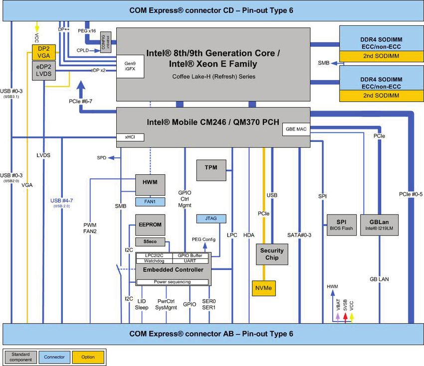
COMe-bCL6 - User Guide Rev 1.99

Customer Support
Find Kontron contacts by visiting: https://www.kontron.de/support-and-services.

Customer Service
As a trusted technology innovator and global solutions provider, Kontron extends its embedded market strengths into
a services portfolio allowing companies to break the barriers of traditional product lifecycles. Proven product expertise
coupled with collaborative and highly-experienced support enables Kontron to provide exceptional peace of mind to
build and maintain successful products.
For more details on Kontron’s service offerings such as: enhanced repair services, extended warranty, Kontron training
academy, and more visit http://www.kontron.com/support-and-services/services.

Customer Comments
If you have any difficulties using this user guide, discover an error, or just want to provide some feedback, contact
Kontron support. Detail any errors you find. We will correct the errors or problems as soon as possible and post the
revised user guide on our website.

www.kontron.com                                                                                                      // 6
COMe-bCL6 - User Guide Rev 1.99

Symbols
The following symbols may be used in this user guide.

                     DANGER indicates a hazardous situation which, if not avoided,
                     will result in death or serious injury.

                     WARNING indicates a hazardous situation which, if not avoided,
                     could result in death or serious injury.

                     NOTICE indicates a property damage message.

                     CAUTION indicates a hazardous situation which, if not avoided,
                     may result in minor or moderate injury.

                     Electric Shock!
                     This symbol and title warn of hazards due to electrical shocks (> 60 V) when touching
                     products or parts of products. Failure to observe the precautions indicated and/or prescribed
                     by the law may endanger your life/health and/or result in damage to your material.

                     ESD Sensitive Device!
                     This symbol and title inform that the electronic boards and their components are sensitive to
                     static electricity. Care must therefore be taken during all handling operations and inspections
                     of this product in order to ensure product integrity at all times.

                     HOT Surface!
                     Do NOT touch! Allow to cool before servicing.

                     Laser!
                     This symbol inform of the risk of exposure to laser beam and light emitting devices (LEDs)
                     from an electrical device. Eye protection per manufacturer notice shall review before
                     servicing.

                     This symbol indicates general information about the product and the user guide.
                     This symbol also indicates detail information about the specific product configuration.

                     This symbol precedes helpful hints and tips for daily use.

www.kontron.com                                                                                                    // 7
COMe-bCL6 - User Guide Rev 1.99
For Your Safety
Your new Kontron product was developed and tested carefully to provide all features necessary to ensure its
compliance with electrical safety requirements. It was also designed for a long fault-free life. However, the life
expectancy of your product can be drastically reduced by improper treatment during unpacking and installation.
Therefore, in the interest of your own safety and of the correct operation of your new Kontron product, you are
requested to conform to the following guidelines.
High Voltage Safety Instructions
As a precaution and in case of danger, the power connector must be easily accessible. The power connector is the
product’s main disconnect device.
Warning
All operations on this product must be carried out by sufficiently skilled personnel only.
Electric Shock!
Before installing a non hot-swappable Kontron product into a system always ensure that
your mains power is switched off. This also applies to the installation of piggybacks. Serious
electrical shock hazards can exist during all installation, repair, and maintenance operations
on this product. Therefore, always unplug the power cable and any other cables which
provide external voltages before performing any work on this product.
Earth ground connection to vehicle’s chassis or a central grounding point shall remain
connected. The earth ground cable shall be the last cable to be disconnected or the first
cable to be connected when performing installation or removal procedures on this product.
Special Handling and Unpacking Instruction
ESD Sensitive Device!
Electronic boards and their components are sensitive to static electricity. Therefore, care
must be taken during all handling operations and inspections of this product, in order to
ensure product integrity at all times.
Do not handle this product out of its protective enclosure while the product is not used for operational purposes
unless the product is otherwise protected.
Whenever possible, unpack or pack this product only at EOS/ESD safe work stations. Where a safe work station is not
guaranteed, it is important for the user to be electrically discharged before touching the product with his/her hands
or tools. This is most easily done by touching a metal part of your system housing.
It is particularly important to observe standard anti-static precautions when changing piggybacks, ROM devices,
jumper settings etc. If the product contains batteries for RTC or memory backup, ensure that the product is not placed
on conductive surfaces, including anti-static plastics or sponges. They can cause short circuits and damage the
batteries or conductive circuits on the product.
www.kontron.com // 8COMe-bCL6 - User Guide Rev 1.99
Lithium Battery Precautions
If your product is equipped with a lithium battery, take the following precautions when replacing the battery.
Danger of explosion if the battery is replaced incorrectly.
Replace only with same or equivalent battery type recommended by the manufacturer.
Dispose of used batteries according to the manufacturer’s instructions.
General Instructions on Usage
In order to maintain Kontron’s product warranty, this product must not be altered or modified in any way. Changes or
modifications to the product, that are not explicitly approved by Kontron and described in this user guide or received
from Kontron Support as a special handling instruction, will void your warranty.
This product should only be installed in or connected to systems that fulfill all necessary technical and specific
environmental requirements. This also applies to the operational temperature range of the specific board version
that must not be exceeded. If batteries are present, their temperature restrictions must be taken into account.
In performing all necessary installation and application operations, only follow the instructions supplied by the
present user guide.
Keep all the original packaging material for future storage or warranty shipments. If it is necessary to store or ship
the product then re-pack it in the same manner as it was delivered.
Special care is necessary when handling or unpacking the product. See Special Handling and Unpacking Instruction.
Quality and Environmental Management
Kontron aims to deliver reliable high-end products designed and built for quality, and aims to complying with
environmental laws, regulations, and other environmentally oriented requirements. For more information regarding
Kontron’s quality and environmental responsibilities, visit http://www.kontron.com/about-kontron/corporate-
responsibility/quality-management.
Disposal and Recycling
Kontron’s products are manufactured to satisfy environmental protection requirements where possible. Many of the
components used are capable of being recycled. Final disposal of this product after its service life must be
accomplished in accordance with applicable country, state, or local laws or regulations.
WEEE Compliance
The Waste Electrical and Electronic Equipment (WEEE) Directive aims to:
Reduce waste arising from electrical and electronic equipment (EEE)
Make producers of EEE responsible for the environmental impact of their products, especially when the product
become waste
Encourage separate collection and subsequent treatment, reuse, recovery, recycling and sound environmental
disposal of EEE
Improve the environmental performance of all those involved during the lifecycle of EEE
Environmental protection is a high priority with Kontron.
Kontron follows the WEEE directive
You are encouraged to return our products for proper disposal.
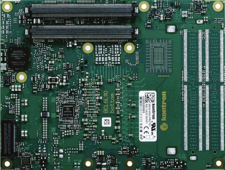
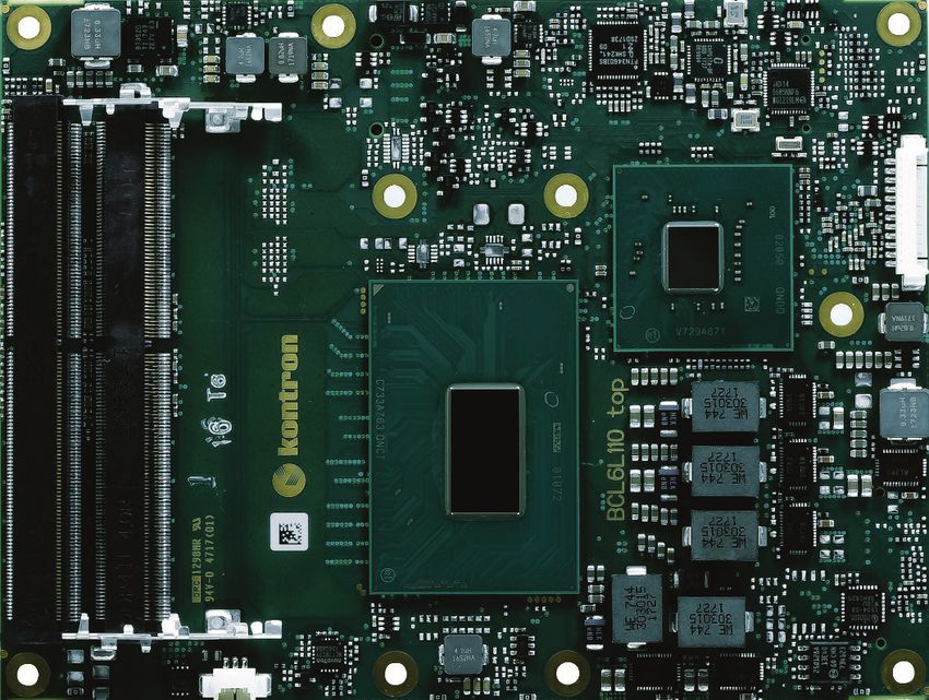
www.kontron.com // 9COMe-bCL6 - User Guide Rev 1.99 Table of Contents Symbols .......................................................................................................................................................................................................... 7 Table of Contents ...................................................................................................................................................................................... 10 List of Tables ................................................................................................................................................................................................ 12 List of Figures .............................................................................................................................................................................................. 13 1/ Introduction .................................................................................................................................................................................... 15 1.1. Product Description ........................................................................................................................................................................................ 15 1.2. Product Naming Clarification ..................................................................................................................................................................... 15 1.3. COM Express® Documentation .................................................................................................................................................................. 15 1.4. COM Express® Functionality ...................................................................................................................................................................... 16 1.5. COM Express® Benefits ................................................................................................................................................................................ 16 2/ Product Specification ................................................................................................................................................................... 17 2.1. Module Variants .............................................................................................................................................................................................. 17 2.1.1. Commercial Grade Modules (0°C to +60°C) ....................................................................................................................................... 17 2.1.2. Extended Temperature Grade Modules (E1, -25 °C to +75 °C)....................................................................................................18 2.1.3. R E2S Modules (R E2S, -40°C to +85°C) ..............................................................................................................................................18 2.2. Accessories....................................................................................................................................................................................................... 19 2.3. Functional Specification ............................................................................................................................................................................. 22 2.3.1. Block Diagram COMe-bCL6..................................................................................................................................................................... 22 2.3.2. Front and Bottom View ........................................................................................................................................................................... 23 2.3.2.1. Front View.................................................................................................................................................................................................. 23 2.3.2.2. Bottom View ............................................................................................................................................................................................. 24 2.3.3. Technical Data ............................................................................................................................................................................................ 25 2.3.4. Processor ...................................................................................................................................................................................................... 26 2.3.5. Chipset ........................................................................................................................................................................................................... 28 2.3.5.1. Platform Controller Hub (PCH) .......................................................................................................................................................... 28 2.3.6. System Memory ......................................................................................................................................................................................... 28 2.3.7. Hardware Monitor (HWM)...................................................................................................................................................................... 28 2.3.8. Trusted Platform Module (TPM) ......................................................................................................................................................... 29 2.3.9. SPI BIOS Memory ....................................................................................................................................................................................... 29 2.3.10. Onboard FAN connector ........................................................................................................................................................................ 29 2.3.11. Rapid Shutdown ........................................................................................................................................................................................ 29 2.3.12. General Purpose PCI Express 3.0 ....................................................................................................................................................... 29 2.3.13. PCI Express Graphics 3.0 (PEG) .......................................................................................................................................................... 30 2.3.14. Universal Serial Bus (USB) ................................................................................................................................................................... 30 2.3.15. Serial ATA 3.0 .............................................................................................................................................................................................. 31 2.3.16. Gigabit Ethernet......................................................................................................................................................................................... 31 2.3.17. Graphic Interfaces.................................................................................................................................................................................... 32 2.3.17.1. Display Resolution ................................................................................................................................................................................ 32 2.3.18. Video Graphics Array (VGA) ................................................................................................................................................................. 32 2.3.19. High Definition (HD) Audio.................................................................................................................................................................... 32 2.3.20. Inter-Integrated Circuit (I2C)-Bus .................................................................................................................................................... 33 2.3.21. Power Supply Control Settings........................................................................................................................................................... 33 2.3.22. General Purpose IOs (GPIOs) .............................................................................................................................................................. 33 2.3.23. Fan Control ................................................................................................................................................................................................ 33 2.3.24. UART Serial Ports .................................................................................................................................................................................... 34 2.3.25. BIOS/Software Features ...................................................................................................................................................................... 34 2.3.26. COMe Features ......................................................................................................................................................................................... 34 www.kontron.com // 10
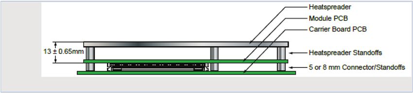
COMe-bCL6 - User Guide Rev 1.99

2.3.27. Kontron Features..................................................................................................................................................................................... 34
2.4. Electrical Specification................................................................................................................................................................................ 35
2.4.1. Power Supply Voltage .............................................................................................................................................................................. 35
2.4.2. Power Supply Rise Time ......................................................................................................................................................................... 35
2.4.3. Power Supply Voltage Ripple................................................................................................................................................................ 35
2.4.4. Power Consumption................................................................................................................................................................................. 35
2.4.6. Power Supply Control Settings ............................................................................................................................................................ 37
2.4.7. Power Supply Modes ............................................................................................................................................................................... 38
2.4.7.1. ATX Mode ................................................................................................................................................................................................... 38
2.4.7.2. Single Supply Mode ............................................................................................................................................................................... 38
2.5. Thermal Management ................................................................................................................................................................................. 39
2.5.1. Heatspreader and Cooling Solutions .................................................................................................................................................. 39
2.5.2. Operating with Kontron Heatspreader Plate (HSP) Assembly................................................................................................. 39
2.5.3. Operating without Kontron Heatspreader Plate Assembly ...................................................................................................... 39
2.5.4. On-board Fan Connector ........................................................................................................................................................................ 39
2.6. Environmental Specification......................................................................................................................................................................41
2.6.1. Temperature .................................................................................................................................................................................................41
2.6.2. Humidity .........................................................................................................................................................................................................41
2.7. Standards and Certifications .................................................................................................................................................................... 42
2.8. MTBF .................................................................................................................................................................................................................. 43
2.9. Mechanical Specification ...........................................................................................................................................................................44
2.9.1. Dimensions ...................................................................................................................................................................................................44
2.9.2. Height .............................................................................................................................................................................................................44
3/           Features and Interfaces ............................................................................................................................................................. 45
3.1. LPC ....................................................................................................................................................................................................................... 45
3.2. Serial Peripheral Interface (SPI)............................................................................................................................................................... 45
3.2.1. SPI boot........................................................................................................................................................................................................... 45
3.2.2. Using an External SPI Flash ................................................................................................................................................................... 46
3.2.3. External SPI flash on Modules with Intel® ME – in the PRD ..................................................................................................... 47
3.2.4. External BIOS ROM Support/SPI .......................................................................................................................................................... 47
3.3. M.A.R.S. .............................................................................................................................................................................................................. 47
3.4. Fast I2C .............................................................................................................................................................................................................. 47
3.5. UART ................................................................................................................................................................................................................... 47
3.6. Triple Staged Watchdog Timer (WDT) ..................................................................................................................................................48
3.6.1. Basics ..............................................................................................................................................................................................................48
3.6.2. WDT Signal ...................................................................................................................................................................................................48
3.7. Real Time Clock (RTC) .................................................................................................................................................................................. 49
3.8. Kontron Security Solution APPROTECT ................................................................................................................................................ 49
3.9. Rapid Shutdown............................................................................................................................................................................................. 49
3.9.1. Crowbar implementation details ......................................................................................................................................................... 49
3.9.2. Shutdown input circuit details ............................................................................................................................................................. 50
4/           System Resources ......................................................................................................................................................................... 51
4.1. Memory Area .................................................................................................................................................................................................... 51
4.2. I/O Address Map ........................................................................................................................................................................................... 52
4.3. Legacy Interrupt (IRQ) lines ...................................................................................................................................................................... 54
4.4. Peripheral Component Interconnect (PCI) Devices ......................................................................................................................... 54
4.5. I2C Bus ............................................................................................................................................................................................................... 54
4.6. System Management (SM) Bus ............................................................................................................................................................... 55
5/           Interface Connectors X1A and X1B .......................................................................................................................................... 56

www.kontron.com                                                                                                                                                                                                                // 11
COMe-bCL6 - User Guide Rev 1.99

5.1. X1A and X1B Signals....................................................................................................................................................................................... 56
5.2. X1A and X1B Pin Assignment ..................................................................................................................................................................... 57
5.2.1. Connector X1A Row A ................................................................................................................................................................................ 57
5.2.2. Connector X1A Row B ............................................................................................................................................................................... 60
5.2.3. Connector X1B Row C ............................................................................................................................................................................... 63
5.2.4. Connector X1B Row D ............................................................................................................................................................................... 66
6/           Maintenance .................................................................................................................................................................................. 69
6.1. Blue Screen after BIOS Update ................................................................................................................................................................. 69
7/           uEFI BIOS ......................................................................................................................................................................................... 70
7.1. Starting the uEFI BIOS................................................................................................................................................................................... 70
7.2. Setup Menus..................................................................................................................................................................................................... 71
7.2.1. Main Setup Menu ........................................................................................................................................................................................ 72
7.2.2. Advanced Setup Menu ............................................................................................................................................................................. 74
7.2.3. Chipset Setup Menu .................................................................................................................................................................................. 80
7.2.3.1. Chipset: System Agent Configuration ..............................................................................................................................................81
7.2.3.2. Chipset > PCH-IO Configuration ........................................................................................................................................................ 82
7.2.4. Security Setup Menu ................................................................................................................................................................................ 85
7.2.4.1. Remember the Password .................................................................................................................................................................... 86
7.2.5. Boot Setup Menu ........................................................................................................................................................................................ 87
7.2.6. Save and Exit Setup Menu ......................................................................................................................................................................88
7.3. The uEFI Shell .................................................................................................................................................................................................. 89
7.3.1. Basic Operation of the uEFI Shell ......................................................................................................................................................... 89
7.3.1.1. Entering the uEFI Shell ........................................................................................................................................................................... 89
7.3.1.2. Exiting the uEFI Shell ............................................................................................................................................................................. 89
7.4. uEFI Shell Scripting ....................................................................................................................................................................................... 90
7.4.1. Startup Scripting ......................................................................................................................................................................................... 90
7.4.2. Create a Startup Script ............................................................................................................................................................................ 90
7.4.3. Examples of Startup Scripts.................................................................................................................................................................. 90
7.4.3.1. Execute Shell Script on Other Harddrive ....................................................................................................................................... 90
7.5. Firmware Update ............................................................................................................................................................................................ 91
7.5.1.1. Updating Procedure ................................................................................................................................................................................. 91
8/           Technical Support ........................................................................................................................................................................ 92
8.1. Warranty ........................................................................................................................................................................................................... 92
8.2. Returning Defective Merchandise .......................................................................................................................................................... 92
Appendix A: List of Acronyms ........................................................................................................................................................................... 94
About Kontron – Member of the S&T Group............................................................................................................................................... 95

List of Tables
Table 1: Pin Assignment of Type 6 and COMe-bCL6 ................................................................................................................................. 16
Table 2: Commercial Grade Modules (0°C to +60°C) ................................................................................................................................ 17
Table 3: R E2S Modules (R E2S, -40°C to +85°C) ........................................................................................................................................18
Table 4: Product Specific Accessories............................................................................................................................................................ 19
Table 5: COMe Type 6 Specific Accessories ................................................................................................................................................ 20
Table 6: General Accessories ............................................................................................................................................................................ 20
Table 7: Memory Modules................................................................................................................................................................................... 21
Table 8: Technical Data ....................................................................................................................................................................................... 25
Table 9: Specifications of the COMe-bCL6 Processor Variants........................................................................................................... 27
Table 10: PCH QM370 and CM246 Features ................................................................................................................................................ 28
Table 11: System Memory ................................................................................................................................................................................... 28

www.kontron.com                                                                                                                                                                                                        // 12
COMe-bCL6 - User Guide Rev 1.99

Table 12: Onboard FAN connector................................................................................................................................................................... 29
Table 13: General Purpose PCI Express 3.0.................................................................................................................................................. 29
Table 14: PCI Express Graphics 3.0 ................................................................................................................................................................. 30
Table 15: Universal Serial Bus (USB) .............................................................................................................................................................. 30
Table 16: USB Overcurrent .................................................................................................................................................................................. 31
Table 17: Serial ATA 3.0 ........................................................................................................................................................................................ 31
Table 18: Supported Ethernet Features ......................................................................................................................................................... 31
Table 19: Digital Display Interfaces Overview ............................................................................................................................................ 32
Table 20: HDA Features ...................................................................................................................................................................................... 32
Table 21: Implemented Power Supply Control Settings ......................................................................................................................... 33
Table 22: Fan Signals ........................................................................................................................................................................................... 33
Table 23: UART Signals........................................................................................................................................................................................ 34
Table 24: BIOS and Software Features ......................................................................................................................................................... 34
Table 25: COMe Specification Features ........................................................................................................................................................ 34
Table 26: Kontron Features ............................................................................................................................................................................... 34
Table 27: Power Supply Specifications ......................................................................................................................................................... 35
Table 28: Single Supply Current Consumption @ 12 V with AVX2 Load ............................................................................................ 35
Table 29: Power Supply and Management ................................................................................................................................................. 36
Table 30: Power Management Options ........................................................................................................................................................ 37
Table 31: Power Supply Control Settings ..................................................................................................................................................... 37
Table 32: ATX Mode Settings ............................................................................................................................................................................ 38
Table 33: Single Supply Mode Settings ......................................................................................................................................................... 38
Table 34: Heatspreader Test Temperature Specifications ................................................................................................................... 39
Table 35: 3-Pin Fan Connector Pin Assignment: ....................................................................................................................................... 39
Table 36: Electrical Characteristics of the Fan Connector .................................................................................................................... 40
Table 37: Temperature Grade Specifications ..............................................................................................................................................41
Table 38: Humidity Specifications ...................................................................................................................................................................41
Table 39: Standards and Certifications......................................................................................................................................................... 42
Table 40: Supported BIOS Features ............................................................................................................................................................... 45
Table 41: SPI Boot Pin Configuration .............................................................................................................................................................. 45
Table 42: Supported SPI Boot Flash Types for 8-SOIC Package ......................................................................................................... 46
Table 43: Reserved SM-Bus Addresses for Smart Battery Solutions on the Carrier ................................................................. 47
Table 44: Triple Stage Watchdog Timer- Time-out Events ..................................................................................................................48
Table 45: Designated memory Locations ..................................................................................................................................................... 51
Table 46: Designated I/O Port Addresses ................................................................................................................................................... 52
Table 47: List of Interrupt Requests............................................................................................................................................................... 54
Table 48: I2C Bus Port Addresses ................................................................................................................................................................... 54
Table 49: Designated I/O Port Addresses ................................................................................................................................................... 55
Table 50: General Signal Description ............................................................................................................................................................. 56
Table 51: Connector X1A Row A Pinout List.................................................................................................................................................. 57
Table 52: Connector X1A Row B Pinout List ................................................................................................................................................. 60
Table 53: Connector X1B Row C Pinout List ................................................................................................................................................. 63
Table 54: Connector X1B Row D Pinout List ................................................................................................................................................ 66
Table 55: Navigation Hot Keys Available in the Legend Bar ................................................................................................................. 70
Table 56: Main Setup Menu Sub-screens and Functions ...................................................................................................................... 72
Table 57: Advanced Setup menu Sub-screens and Functions ............................................................................................................. 74
Table 58: Chipset: System Agent Configuration Sub-screens and Functions ................................................................................81
Table 59: Chipset Set > PCH-IO Configuration Sub-screens and Functions .................................................................................. 82
Table 60: Security Setup Menu Functions ................................................................................................................................................... 85
Table 61: Boot Setup Menu Functions ........................................................................................................................................................... 87
Table 62: Save and Exit Setup Menu Functions .........................................................................................................................................88

List of Figures
Figure 1: Block Diagram COMe-bCL6 .............................................................................................................................................................. 22
Figure 2: Front View COMe-bCL6 .................................................................................................................................................................... 23

www.kontron.com                                                                                                                                                                                                // 13
You can also read