COMe-cAL6 - USER GUIDE - Kontron
←
→
Page content transcription
If your browser does not render page correctly, please read the page content below
USER GUIDE
COMe-cAL6
Doc. User Guide Rev.1.5
Doc. ID: 1061-1953
www.kontron.com // 1
COMe-cAL6 – User Guide Rev.1.5

                  This page has been intentionally left blank

www.kontron.com                                                                           // 2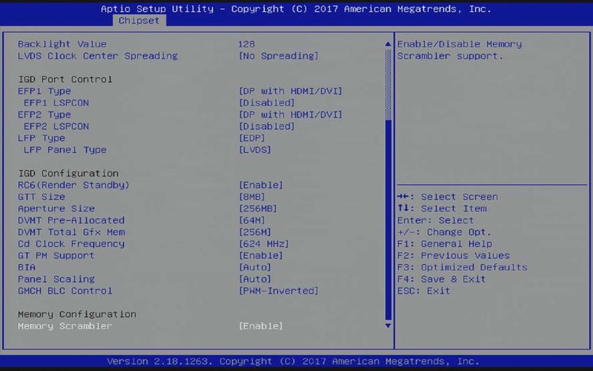
COMe-cAL6 – User Guide Rev.1.5 COME-CAL6 - USER GUIDE Disclaimer Kontron would like to point out that the information contained in this user guide may be subject to alteration, particularly as a result of the constant upgrading of Kontron products. This document does not entail any guarantee on the part of Kontron with respect to technical processes described in the user guide or any product characteristics set out in the user guide. Kontron assumes no responsibility or liability for the use of the described product(s), conveys no license or title under any patent, copyright or mask work rights to these products and makes no representations or warranties that these products are free from patent, copyright or mask work right infringement unless otherwise specified. Applications that are described in this user guide are for illustration purposes only. Kontron makes no representation or warranty that such application will be suitable for the specified use without further testing or modification. Kontron expressly informs the user that this user guide only contains a general description of processes and instructions which may not be applicable in every individual case. In cases of doubt, please contact Kontron. This user guide is protected by copyright. All rights are reserved by Kontron. No part of this document may be reproduced, transmitted, transcribed, stored in a retrieval system, or translated into any language or computer language, in any form or by any means (electronic, mechanical, photocopying, recording, or otherwise), without the express written permission of Kontron. Kontron points out that the information contained in this user guide is constantly being updated in line with the technical alterations and improvements made by Kontron to the products and thus this user guide only reflects the technical status of the products by Kontron at the time of publishing. Brand and product names are trademarks or registered trademarks of their respective owners. ©2017 by Kontron S&T AG Kontron S&T AG Lise-Meitner-Str. 3-5 86156 Augsburg Germany www.kontron.com www.kontron.com // 3
COMe-cAL6 – User Guide Rev.1.5

High Risk Applications Hazard Notice
THIS DEVICE AND ASSOCIATED SOFTWARE ARE NOT DESIGNED, MANUFACTURED OR INTENDED FOR USE
OR RESALE FOR THE OPERATION OF NUCLEAR FACILITIES, THE NAVIGATION, CONTROL OR
COMMUNICATION SYSTEMS FOR AIRCRAFT OR OTHER TRANSPORTATION, AIR TRAFFIC CONTROL, LIFE
SUPPORT OR LIFE SUSTAINING APPLICATIONS, WEAPONS SYSTEMS, OR ANY OTHER APPLICATION IN A
HAZARDOUS ENVIRONMENT, OR REQUIRING FAIL-SAFE PERFORMANCE, OR IN WHICH THE FAILURE OF
PRODUCTS COULD LEAD DIRECTLY TO DEATH, PERSONAL INJURY, OR SEVERE PHYSICAL OR
ENVIRONMENTAL DAMAGE (COLLECTIVELY, "HIGH RISK APPLICATIONS").
You understand and agree that your use of Kontron devices as a component in High Risk Applications is entirely at
your risk. To minimize the risks associated with your products and applications, you should provide adequate design
and operating safeguards. You are solely responsible for compliance with all legal, regulatory, safety, and security
related requirements concerning your products. You are responsible to ensure that your systems (and any Kontron
hardware or software components incorporated in your systems) meet all applicable requirements. Unless otherwise
stated in the product documentation, the Kontron device is not provided with error-tolerance capabilities and cannot
therefore be deemed as being engineered, manufactured or setup to be compliant for implementation or for resale as
device in High Risk Applications. All application and safety related information in this document (including application
descriptions, suggested safety measures, suggested Kontron products, and other materials) is provided for reference
only.

www.kontron.com                                                                                                     // 4
COMe-cAL6 – User Guide Rev.1.5

Revision History

 Revision   Brief Description of Changes                                                   Date of Issue     Author/
                                                                                                             Editor
 1.0        Initial version                                                                2017-Oct-17       CW
 1.1        Included metal heat slug dimensions and information in Ch.2.5.1 and 2.8.3      2018-May-24       CW
 1.2        Updates pSLC information in Chapters 2.3.13 and 3.1                            2019-Apr-01       CW
 1.3        Included the MTBF graphs                                                       2020-Jan-08       CW
 1.4        Extended Specification of COMe-cAL6 Processor Variants Table 8                 2020-May-14       CW
 1.5        Updated Accessories List                                                       2020-Jul-23       CW

Terms and Conditions
Kontron warrants products in accordance with defined regional warranty periods. For more information about
warranty compliance and conformity, and the warranty period in your region, visit http://www.kontron.com/terms-
and-conditions.
Kontron sells products worldwide and declares regional General Terms & Conditions of Sale, and Purchase Order
Terms & Conditions. Visit http://www.kontron.com/terms-and-conditions.

For contact information, refer to the corporate offices contact information on the last page of this user guide or visit
our website CONTACT US.

Customer Support
Find Kontron contacts by visiting: http://www.kontron.com/support.

Customer Service
As a trusted technology innovator and global solutions provider, Kontron extends its embedded market strengths into
a services portfolio allowing companies to break the barriers of traditional product lifecycles. Proven product
expertise coupled with collaborative and highly-experienced support enables Kontron to provide exceptional peace of
mind to build and maintain successful products.
For more details on Kontron’s service offerings such as: enhanced repair services, extended warranty, Kontron
training academy, and more visit http://www.kontron.com/support-and-services/services.

Customer Comments
If you have any difficulties using this user guide, discover an error, or just want to provide some feedback, contact
Kontron support. Detail any errors you find. We will correct the errors or problems as soon as possible and post the
revised user guide on our website.

www.kontron.com                                                                                                     // 5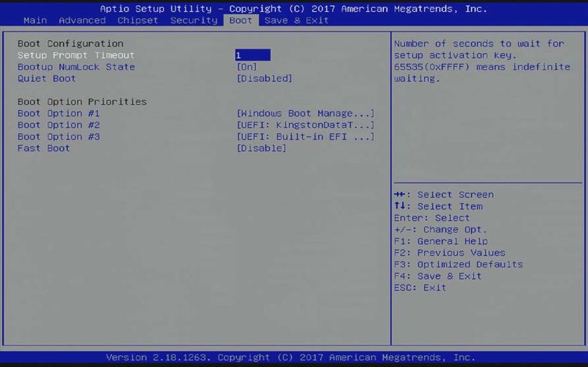
COMe-cAL6 – User Guide Rev.1.5

Symbols
The following symbols may be used in this user guide

                    DANGER indicates a hazardous situation which, if not avoided,
                    will result in death or serious injury.

                    WARNING indicates a hazardous situation which, if not avoided,
                    could result in death or serious injury.

                    NOTICE indicates a property damage message.

                    CAUTION indicates a hazardous situation which, if not avoided,
                    may result in minor or moderate injury.

                    Electric Shock!
                    This symbol and title warn of hazards due to electrical shocks (> 60 V) when touching
                    products or parts of products. Failure to observe the precautions indicated and/or
                    prescribed by the law may endanger your life/health and/or result in damage to your
                    material.

                    ESD Sensitive Device!
                    This symbol and title inform that the electronic boards and their components are sensitive
                    to static electricity. Care must therefore be taken during all handling operations and
                    inspections of this product in order to ensure product integrity at all times.

                    HOT Surface!
                    Do NOT touch! Allow to cool before servicing.

                    Laser!
                    This symbol inform of the risk of exposure to laser beam and light emitting devices (LEDs)
                    from an electrical device. Eye protection per manufacturer notice shall review before
                    servicing.

                    This symbol indicates general information about the product and the user guide.
                    This symbol also indicates detail information about the specific product configuration.

                    This symbol precedes helpful hints and tips for daily use.

www.kontron.com                                                                                                  // 6
COMe-cAL6 – User Guide Rev.1.5

For Your Safety
Your new Kontron product was developed and tested carefully to provide all features necessary to ensure its
compliance with electrical safety requirements. It was also designed for a long fault-free life. However, the life
expectancy of your product can be drastically reduced by improper treatment during unpacking and installation.
Therefore, in the interest of your own safety and of the correct operation of your new Kontron product, you are
requested to conform with the following guidelines.

High Voltage Safety Instructions
As a precaution and in case of danger, the power connector must be easily accessible. The power connector is the
product’s main disconnect device.

                     Warning
                     All operations on this product must be carried out by sufficiently skilled personnel only.

                     Electric Shock!
                     Before installing a non hot-swappable Kontron product into a system always ensure that
                     your mains power is switched off. This also applies to the installation of piggybacks. Serious
                     electrical shock hazards can exist during all installation, repair, and maintenance operations
                     on this product. Therefore, always unplug the power cable and any other cables which
                     provide external voltages before performing any work on this product.
                     Earth ground connection to vehicle’s chassis or a central grounding point shall remain
                     connected. The earth ground cable shall be the last cable to be disconnected or the first
                     cable to be connected when performing installation or removal procedures on this product.

Special Handling and Unpacking Instruction

                     ESD Sensitive Device!
                     Electronic boards and their components are sensitive to static electricity. Therefore, care
                     must be taken during all handling operations and inspections of this product, in order to
                     ensure product integrity at all times.

                     Handling and operation of the product is permitted only for trained personnel within a work
                     place that is access controlled. Follow the “General Safety Instructions for IT Equipment”
                     supplied with the system.

Do not handle this product out of its protective enclosure while it is not used for operational purposes unless it is
otherwise protected.
Whenever possible, unpack or pack this product only at EOS/ESD safe work stations. Where a safe work station is not
guaranteed, it is important for the user to be electrically discharged before touching the product with his/her hands
or tools. This is most easily done by touching a metal part of your system housing.
It is particularly important to observe standard anti-static precautions when changing piggybacks, ROM devices,
jumper settings etc. If the product contains batteries for RTC or memory backup, ensure that the product is not placed
on conductive surfaces, including anti-static plastics or sponges. They can cause short circuits and damage the
batteries or conductive circuits on the product.

www.kontron.com                                                                                                         // 7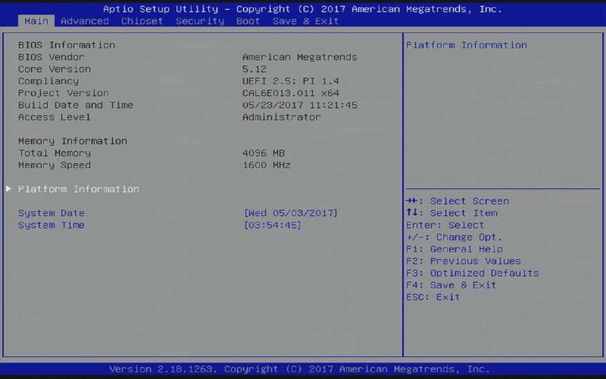
COMe-cAL6 – User Guide Rev.1.5
Lithium Battery Precautions
If your product is equipped with a lithium battery, take the following precautions when replacing the battery.
Danger of explosion if the battery is replaced incorrectly.
Replace only with same or equivalent battery type recommended by the manufacturer.
Dispose of used batteries according to the manufacturer’s instructions.
General Instructions on Usage
In order to maintain Kontron’s product warranty, this product must not be altered or modified in any way. Changes or
modifications to the product, that are not explicitly approved by Kontron and described in this user guide or received
from Kontron Support as a special handling instruction, will void your warranty.
This product should only be installed in or connected to systems that fulfill all necessary technical and specific
environmental requirements. This also applies to the operational temperature range of the specific board version
that must not be exceeded. If batteries are present, their temperature restrictions must be taken into account.
In performing all necessary installation and application operations, only follow the instructions supplied by the
present user guide.
Keep all the original packaging material for future storage or warranty shipments. If it is necessary to store or ship
the product then re-pack it in the same manner as it was delivered.
Special care is necessary when handling or unpacking the product. See, Special Handling and Unpacking Instruction.
Quality and Environmental Management
Kontron aims to deliver reliable high-end products designed and built for quality, and aims to complying with
environmental laws, regulations, and other environmentally oriented requirements. For more information regarding
Kontron’s quality and environmental responsibilities, visit http://www.kontron.com/about-kontron/corporate-
responsibility/quality-management.
Disposal and Recycling
Kontron’s products are manufactured to satisfy environmental protection requirements where possible. Many of the
components used are capable of being recycled. Final disposal of this product after its service life must be
accomplished in accordance with applicable country, state, or local laws or regulations.
WEEE Compliance
The Waste Electrical and Electronic Equipment (WEEE) Directive aims to:
Reduce waste arising from electrical and electronic equipment (EEE)
Make producers of EEE responsible for the environmental impact of their products, especially when the product
become waste
Encourage separate collection and subsequent treatment, reuse, recovery, recycling and sound environmental
disposal of EEE
Improve the environmental performance of all those involved during the lifecycle of EEE
Environmental protection is a high priority with Kontron.
Kontron follows the WEEE directive
You are encouraged to return our products for proper disposal.
www.kontron.com // 8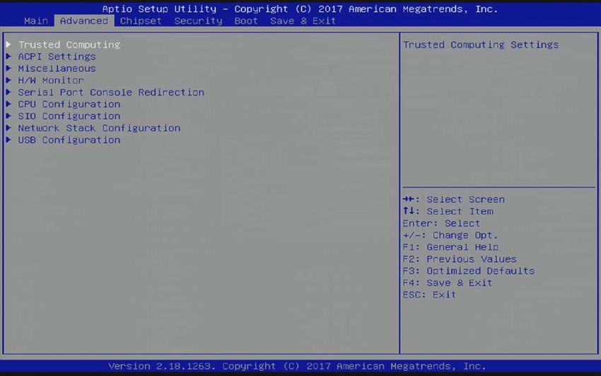
COMe-cAL6 – User Guide Rev.1.5

Table of Contents
Symbols .................................................................................................................................................................................................................6
For Your Safety.................................................................................................................................................................................................... 7
High Voltage Safety Instructions .................................................................................................................................................................. 7
Special Handling and Unpacking Instruction ............................................................................................................................................ 7
Lithium Battery Precautions .......................................................................................................................................................................... 8
General Instructions on Usage...................................................................................................................................................................... 8
Quality and Environmental Management ................................................................................................................................................. 8
Disposal and Recycling.................................................................................................................................................................................... 8
WEEE Compliance.............................................................................................................................................................................................. 8
Table of Contents ...............................................................................................................................................................................................9
List of Tables.......................................................................................................................................................................................................11
List of Figures .................................................................................................................................................................................................... 12
1/           Introduction .......................................................................................................................................................................................... 13
1.1. Product Description................................................................................................................................................................................... 13
1.2. Product Naming Clarification ................................................................................................................................................................ 13
1.3. COM Express® Documentation ............................................................................................................................................................. 13
1.4. Com Express® Functionality ..................................................................................................................................................................14
1.5. COM Express® Benefits ...........................................................................................................................................................................14
2/           Product Specification ........................................................................................................................................................................ 15
2.1. Module Variants ........................................................................................................................................................................................ 15
2.1.1. Commercial Temperature Grade Modules 0°C to +60°C ........................................................................................................... 15
2.1.2. Industrial Temperature Grade Modules E2-40°C to +85°C...................................................................................................... 15
2.2. Accessories................................................................................................................................................................................................. 16
2.3. Functional Specification .........................................................................................................................................................................18
2.3.1. Block Diagram COMe-cAL6 .................................................................................................................................................................18
2.3.2. Processor ................................................................................................................................................................................................. 19
2.3.3. Platform Controller Hub .................................................................................................................................................................... 20
2.3.4. System Memory ................................................................................................................................................................................... 20
2.3.5. Graphics.................................................................................................................................................................................................... 21
2.3.6. LVDS........................................................................................................................................................................................................... 21
2.3.7. AUDIO ....................................................................................................................................................................................................... 22
2.3.8. PCI Express (PCIE) Lanes [0-4] ........................................................................................................................................................ 22
2.3.9. USB............................................................................................................................................................................................................ 23
2.3.10. SATA........................................................................................................................................................................................................ 23
2.3.11. Ethernet.................................................................................................................................................................................................. 24
2.3.12. COMe High-speed Interfaces ......................................................................................................................................................... 24
2.3.13. Storage Features ................................................................................................................................................................................ 25
2.3.14. BIOS/Software Features.................................................................................................................................................................. 25
2.3.15. COM Features ...................................................................................................................................................................................... 25
2.3.16. Kontron Features................................................................................................................................................................................ 25
2.4. Electrical Specification .......................................................................................................................................................................... 26
2.4.1. Power Supply Voltage Specification .............................................................................................................................................. 26
2.4.2. Power Management ........................................................................................................................................................................... 26
2.4.3. Power Supply Control Settings ....................................................................................................................................................... 27
2.4.4. Power Supply Modes.......................................................................................................................................................................... 27
2.5. Thermal Management ........................................................................................................................................................................... 29

www.kontron.com                                                                                                                                                                                                        // 9
COMe-cAL6 – User Guide Rev.1.5

2.5.1. Heatspreader Plate (HSP) Assembly and Metal Heat Slug ..................................................................................................... 29
2.5.2. Active or Passive Cooling Solutions ............................................................................................................................................... 29
2.5.3. Operating with Kontron Heatspreader Plate (HSP) Assembly.............................................................................................. 29
2.5.4. Operating without Kontron Heatspreader Plate (HSP) Assembly....................................................................................... 29
2.6. Environmental Specification................................................................................................................................................................. 31
2.6.1. Temperature............................................................................................................................................................................................ 31
2.6.2. Humidity ................................................................................................................................................................................................... 31
2.7. Standards and Certifications ............................................................................................................................................................... 32
2.7.1. MTBF ......................................................................................................................................................................................................... 33
2.8. Mechanical Specification ...................................................................................................................................................................... 35
2.8.1. Module Dimensions ............................................................................................................................................................................. 35
2.8.2. Module Height ....................................................................................................................................................................................... 35
2.8.3. Heatspreader Dimensions ................................................................................................................................................................ 36
3/           Features and Interfaces .................................................................................................................................................................. 37
3.1. eMMC Flash Memory .............................................................................................................................................................................. 37
3.2. Micro SD Card............................................................................................................................................................................................ 37
3.3. LPC ................................................................................................................................................................................................................ 38
3.4. Serial Peripheral Interface (SPI) ......................................................................................................................................................... 38
3.4.1. SPI Boot .................................................................................................................................................................................................... 38
3.4.2. Booting from an External SPI Flash ............................................................................................................................................... 39
3.4.3. External SPI Flash on Modules with Intel® ME .......................................................................................................................... 40
3.5. Fast I2C ........................................................................................................................................................................................................40
3.6. UART ............................................................................................................................................................................................................40
3.7. Dual Staged Watchdog Timer (WDT) ................................................................................................................................................ 40
3.7.1. WDT Signal ...............................................................................................................................................................................................41
3.8. GPIO...............................................................................................................................................................................................................41
3.9. Real Time Clock (RTC) .............................................................................................................................................................................41
3.10. Trusted Platform Module (TPM 2.0) ................................................................................................................................................41
3.11. Kontron Security Solution .................................................................................................................................................................... 42
3.12. SpeedStep® Technology ...................................................................................................................................................................... 42
4/           System Resources............................................................................................................................................................................. 43
4.1. Interrupt Request (IRQ) Lines .............................................................................................................................................................. 43
4.2. Memory Area ............................................................................................................................................................................................ 43
4.3. I/O Address Map ......................................................................................................................................................................................44
4.4. Peripheral Component Interconnect (PCI) Devices ..................................................................................................................... 45
4.5. I2C Bus......................................................................................................................................................................................................... 45
4.6. System Management (SM) Bus .......................................................................................................................................................... 46
5/           COMe Interface Connectors ........................................................................................................................................................... 47
5.1. X1A and X1B Signals ................................................................................................................................................................................. 47
5.2. X1A and X1B Pin Assignment ................................................................................................................................................................48
5.2.1. Connector X1A Row A1 – A110 ........................................................................................................................................................... 49
5.2.2. Connector X1A Row B 1 - B 110 ......................................................................................................................................................... 52
5.2.3. Connector X1B Row C 1 - C 110 .......................................................................................................................................................... 55
5.2.4. Connector X1B Row D 1 - D 110 ......................................................................................................................................................... 58
6/           uEFI BIOS................................................................................................................................................................................................ 61
6.1. Starting the uEFI BIOS .............................................................................................................................................................................. 61
6.2. Setup Menus ............................................................................................................................................................................................. 62
6.2.1. Main Setup Menu .................................................................................................................................................................................. 63
6.2.2. Advanced Setup Menu........................................................................................................................................................................ 64

www.kontron.com                                                                                                                                                                                                        // 10
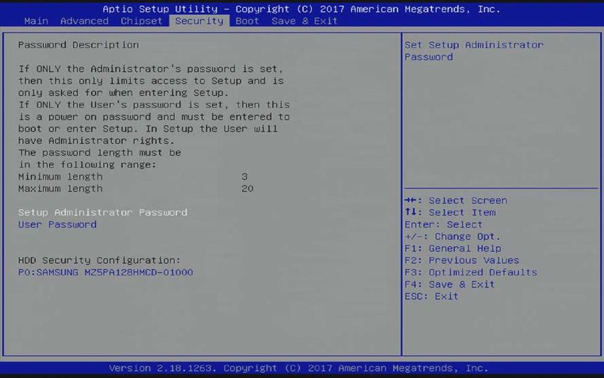
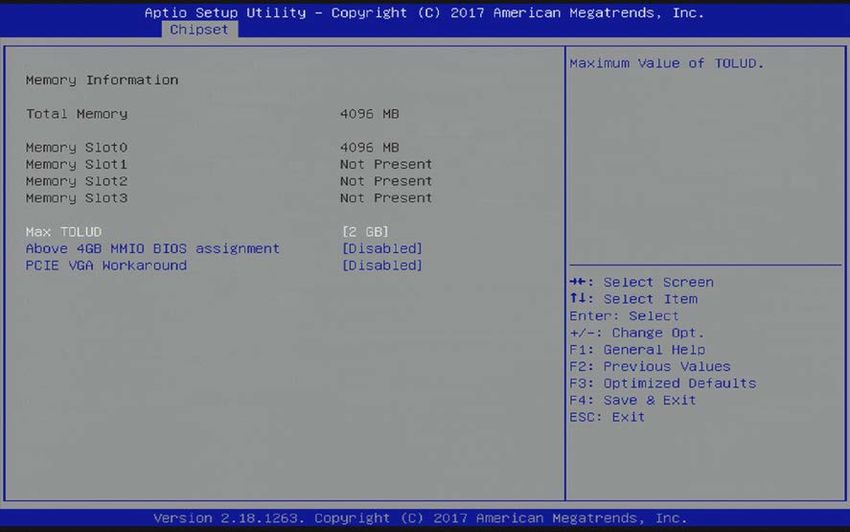
COMe-cAL6 – User Guide Rev.1.5

6.2.3. Chipset Setup Menu ............................................................................................................................................................................. 71
6.2.4. Security Setup Menu ............................................................................................................................................................................81
6.2.5. Boot Setup Menu .................................................................................................................................................................................. 83
6.2.6. Save and Exit Setup Menu................................................................................................................................................................. 85
6.3. The uEFI Shell............................................................................................................................................................................................ 87
6.3.1. Basic Operation of the uEFI Shell .................................................................................................................................................... 87
6.4. uEFI Shell Scripting .................................................................................................................................................................................88
6.4.1. Startup Scripting ...................................................................................................................................................................................88
6.4.2. Create a Startup Script .......................................................................................................................................................................88
6.4.3. Example of Startup Scripts...............................................................................................................................................................88
6.5. Firmware Update .....................................................................................................................................................................................88
6.5.1. Updating Procedure .............................................................................................................................................................................88
Appendix A: List of Acronyms...................................................................................................................................................................... 90
About Kontron .................................................................................................................................................................................................. 92

List of Tables
Table 1: Type 6 and COMe-cAL6 Functionality........................................................................................................................................14
Table 2: Product Number for Commercial Grade Modules (0°C to +60°C operating)................................................................ 15
Table 3: Product number for Industrial Grade Modules E2 (-40°C to +85°C operating) .......................................................... 15
Table 4: Product Specific Accessories ....................................................................................................................................................... 16
Table 5: COMe Type 6 Accessories ............................................................................................................................................................. 16
Table 6: General COMe Accessories ........................................................................................................................................................... 16
Table 7: Memory Modules ............................................................................................................................................................................. 17
Table 8: Specification of the COMe-cAL6 Processor Variants .......................................................................................................... 19
Table 9: Heatspreader Test Temperature Specifications .................................................................................................................. 29
Table 10: 3-Pin Fan Connector Pin Assignment..................................................................................................................................... 30
Table 11: Electrical Characteristics of the Fan Connector .................................................................................................................. 30
Table 12: Temperature Grade Specifications .......................................................................................................................................... 31
Table 13: Humidity Specification.................................................................................................................................................................. 31
Table 14: MTBF Estimated Values .............................................................................................................................................................. 33
Table 15: Supported BIOS Features ........................................................................................................................................................... 38
Table 16: SPI Boot Pin Configuration ......................................................................................................................................................... 39
Table 17: Supported SPI Boot Flash Types for 8-SOIC Package ....................................................................................................... 39
Table 18: Dual Stage Watchdog Timer- Time-out Events ................................................................................................................. 40
Table 19: Interrupt Requests........................................................................................................................................................................ 43
Table 20: Designated Memory Locations ................................................................................................................................................ 43
Table 21: Designated I/O Port Address ....................................................................................................................................................44
Table 22: I2C Bus Port Address ................................................................................................................................................................... 45
Table 23: SMBus Address ............................................................................................................................................................................. 46
Table 24: General Signal Description ........................................................................................................................................................48
Table 25: Connector X1A Row A Pin Assignment (A1-A110) ............................................................................................................... 49
Table 26: Connector X1A Row B Pin Assignment (B1 -B110) .............................................................................................................. 52
Table 27: Connector X1B Row C Pin Assignment (C1 -C110) ............................................................................................................... 55
Table 28: Connector X1B Row D Pin Assignment (D1 -D110) ............................................................................................................. 58
Table 29: Navigation Hot Keys Available in the Legend Bar............................................................................................................... 61
Table 30: Main Setup Menu Sub-screens and Functions .................................................................................................................. 63
Table 31: Advanced Setup menu Sub-screens and Functions .......................................................................................................... 64
Table 32: Chipset> North Bridge Sub-screens and Function ............................................................................................................. 71
Table 33: Chipset> South Bridge Sub-screens and Functions.......................................................................................................... 72
Table 34: Chipset> Uncore Configuration Sub-screens and Functions......................................................................................... 74
Table 35: Chipset>South Cluster Configuration Menu Sub-screens and Functions ................................................................. 76
Table 36: Security Setup Menu Sub-screens and Functions .............................................................................................................81
Table 37: Boot Setup Menu Sub-screens and Functions ................................................................................................................... 83

www.kontron.com                                                                                                                                                                                                // 11
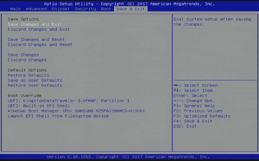
COMe-cAL6 – User Guide Rev.1.5

Table 38: Save and Exit Setup Menu Sub-screens and Functions .................................................................................................. 85
Table 39: List of Acronyms ........................................................................................................................................................................... 90

List of Figures
Figure 1: Block Diagram COMe-cAL6 ..........................................................................................................................................................18
Figure 2: MTBF De-rating Values @ 40°C for the COMe- cAL6 N4200 (MTBF: 829207 hours) ............................................. 33
Figure 3: MTBF De-rating Values @ 40°C for the COMe- cAL6 E2 E3950 32S (MTBF: 684743 hours) ................................ 34
Figure 4: Module Dimensions ...................................................................................................................................................................... 35
Figure 5: Module Height ................................................................................................................................................................................ 36
Figure 6: Heatspreader and Metal Heat Slug Dimensions ................................................................................................................. 36
Figure 7: X1A and X1B COMe Interface Connectors............................................................................................................................... 47
Figure 8: Main Setup Menu Initial Screen ................................................................................................................................................ 63
Figure 9: Advanced Setup Menu Initial Screen ...................................................................................................................................... 64
Figure 10: Chipset > North Bridge Menu Initial Screen ......................................................................................................................... 71
Figure 11: Chipset > South Bridge Menu Initial Screen ......................................................................................................................... 72
Figure 12: Chipset>Uncore Configuration Menu Initial Screens ....................................................................................................... 73
Figure 13: Chipset>South Cluster Configuration Menu Initial Screen............................................................................................. 76
Figure 14: Security Setup Menu Initial Screen .........................................................................................................................................81
Figure 15: Boot Setup Menu Initial Screen ............................................................................................................................................... 83
Figure 16: Save and Exit Setup Menu Initial Screen.............................................................................................................................. 85

www.kontron.com                                                                                                                                                                                        // 12
COMe-cAL6 – User Guide Rev.1.5
1/ Introduction
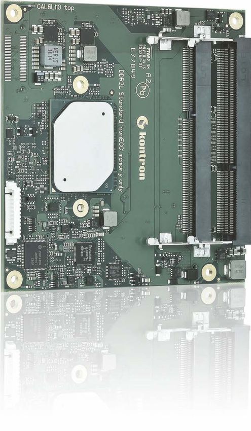
1.1. Product Description
The COMe-cAL6 is a compact form factor, COM Express® type 6 Computer-on-Module based on Intel® Apollo Lake®
series of processors Atom™, Pentium® and Celeron®, with an integrated chipset. The COMe-cAL6 combines increased
efficiency and performance with TDP as low as 6 W, and no more than 12 W with Intel’s® extensive HD Graphics
capabilities.
The main COMe-cAL6 features are:
Intel® Apollo Lake® series of processors with integrated chipset
Up to 8 GByte DDR3L 1600/1866 (non-ECC) with 2x SO-DIMM sockets
High-speed connectivity includes: up to 5x PCIe x1, 4x USB 3.0 (including USB 2.0) + 4x USB 2.0, and
2x SATA Gen 3 (6 Gb/s)
Support for both commercial and Industrial temperature grade environments
1.2. Product Naming Clarification
COM Express® defines a Computer-on-Module, or COM, with all the components necessary for a bootable host
computer, packaged as a super component. The product names for Kontron COM Express® Computer-on-Modules
consist of:
Short form of the industry standard
COMe-
Module form factor
b=basic (125mm x 95mm)
c=compact (95mm x 95mm)
m=mini (84mm x 55mm)
Intel’s processor code name
AL = Apollo Lake
Pinout type
Type 6
Type 7
Type10
Available temperature variants
Commercial
Extended (E1)
Industrial (E2)
Screened industrial (E2S) and Rapid shutdown screened industrial (R E2S)
Processor Identifier
Chipset identifier (if chipset assembled)
Memory size
Memory down + DIMM memory (#GB) / eMMC pSLC memory (#S)
1.3. COM Express® Documentation
The COM Express® Specification defines the COM Express® module form factor, pinout and signals. The COM Express
document is available at the PICMG® website.
www.kontron.com // 13COMe-cAL6 – User Guide Rev.1.5
1.4. Com Express® Functionality
All Kontron COM Express® basic and compact modules contain two 220-pin connectors; each of it has two rows
called Row A & B on primary connector and Row C & D on secondary connector. COM Express® Computer-on-
Modules feature the following maximum amount of interfaces according to the PICMG module pinout type.
Table 1: Type 6 and COMe-cAL6 Functionality
Feature Type 6 Pinout COMe-cAL6 Pinout
HD Audio 1x 1x
Gbit Ethernet 1x 1x
Serial ATA 4x 2x
PCI Express x 1 8x 5x
PCI Express x16 (PEG) 1x Not supported
USB Client 1x 1x (USB Port 0 is dual role Client/Host)
USB 4x USB 3.0 (Including USB 2.0) 4x USB 3.0 (Including USB 2.0)
4x USB 2.0 4x USB 2.0
VGA 1x Not supported
LVDS Dual Channel Dual Channel LVDS with optional
embedded display port (eDP) overlay
DP++ (eDP/DP/HDMI/DVI/VGA) 3x 2x
LPC 1x 1x
External SMB 1x 1x
External I2C 1x 1x
GPIO 8x 8x (4x GPI, 4x GPO)
SDIO shared w/GPIO 1x optional Not supported
UART (2-wire COM) 2x 2x
FAN PWM out 1x 1x
Express Card 2x 2x
1.5. COM Express® Benefits
COM Express® defines a Computer-on-Module, or COM, with all the components necessary for a bootable host
computer, packaged as highly integrated computer. All Kontron COM Express® modules are very compact and feature
a standardized form factor and a standardized connector layout that carry a specified set of signals. Each COM is
based on the COM Express® specification. This standardization allows designers to create a single-system baseboard
that can accept present and future COM Express® modules.
The baseboard designer can optimize exactly how each of these functions implements physically. Designers can
place connectors precisely where needed for the application, on a baseboard optimally designed to fit a system’s
packaging.
A single baseboard design can use a range of COM Express® modules with different sizes and pinouts. This flexibility
differentiates products at various price and performance points and provides a built-in upgrade path when designing
future-proof systems. The modularity of a COM Express® solution also ensures against obsolescence when computer
technology evolves. A properly designed COM Express® baseboard can work with several successive generations of
COM Express® modules.
A COM Express® baseboard design has many advantages of a customized computer-board design and, additionally,
delivers better obsolescence protection, heavily reduced engineering effort, and faster time to market.
www.kontron.com // 14COMe-cAL6 – User Guide Rev.1.5
2/ Product Specification
2.1. Module Variants
The COMe-cAL6 is available in different processor and chipset variants to cover demands in performance, price and
power.
2.1.1. Commercial Temperature Grade Modules 0°C to +60°C
Table 2: Product Number for Commercial Grade Modules (0°C to +60°C operating)
Product Number Product Name Description
36023-0000-11-4 COMe-cAL6 N4200 COM Express® compact pin-out type 6 Computer-on-
Module with Intel® Pentium® N4200, commercial grade
36023-0000-11-2 COMe-cAL6 N3350 COM Express® compact pin-out type 6 Computer-on-
Module with Intel® Celeron® N3350,commercial grade
2.1.2. Industrial Temperature Grade Modules E2-40°C to +85°C
Table 3: Product number for Industrial Grade Modules E2 (-40°C to +85°C operating)
Product Number Product Name Description
36024-0032-16-7 COMe-cAL6 E2 E3950 32S PCIe COM Express® compact pin-out type 6 Computer-on-
Module with Intel® Atom™ x7 E3950, 32 GB pSLC eMMC,
PCIe Hub, industrial temperature
36024-0000-16-7 COMe-cAL6 E2 E3950 COM Express® compact pin-out type 6 Computer-on-
Module with Intel® Atom™ x7 E3950, industrial
temperature
36024-0000-16-5 COMe-cAL6 E2 E3940 COM Express® compact pin-out type 6 Computer-on-
Module with Intel® Atom™ x5 E3940, industrial
temperature
36024-0000-13-5 COMe-cAL6 E2 E3930 COM Express® compact pin-out type 6 Computer-on-
Module with Intel® Atom™ x5 E3930, industrial
temperature
www.kontron.com // 15COMe-cAL6 – User Guide Rev.1.5
2.2. Accessories
Accessories are either COMe-cAL6 product specific, COMe type 6 specific, or general accessories including memory
modules. For more information, contact your local Kontron sales representative or Kontron Inside Sales.
Table 4: Product Specific Accessories
Part Number Heatspreader ( validated ref. types) Description
36024-0000-99-0 HSP COMe-cAL6 E2 thread Heatspreader for COMe-cAL6 E2, threaded mounting
holes
36024-0000-99-1 HSP COMe-cAL6 E2 through Heatspreader for COMe-cAL6 E2, through holes
Table 5: COMe Type 6 Accessories
Part Number COMe Carrier Project Code Description
38115-0000-00-x COM Express® Ref. Carrier-i Type 6 ADTI Thin-mITX carrier with 5 mm COMe
connector
38116-0000-00-5 COM Express® Eval. Carrier2 Type 6 ADT6 ATX carrier with 5 mm COMe
connector
Part Number COMe Adapter / Card Project Code Description
96007-0000-00-3 ADA-PCIe-DP APDP PCIe x16 to DP Adapter for Evaluation
carrier
96007-0000-00-7 ADA-Type6-DP3 DVO6 (Sandwich) Adapter Card for 3x
Display Port
96006-0000-00-2 COMe POST T6 NFCB POST Code / Debug Card
38019-0000-00-0 ADA-COMe-Height-dual EERC Height Adapter
Table 6: General COMe Accessories
Part Number Cooling Solutions Description
36099-0000-99-0 COMe Active Uni cooler For CPUs up to 20 W TDP, to be mounted on HSP
36099-0000-99-1 COMe Passive Uni Cooler For CPUs up to 10 W TDP, to be mounted on HSP
Part Number Mounting Description
38017-0000-00-5 COMe Mount KIT 5 mm 1 set Mounting Kit for 1 module
including screws for 5 mm connectors
38017-0100-00-5 COMe Mount KIT 5 mm 100 sets Mounting Kit for 100 modules
including screws for 5 mm connectors
38017-0000-00-0 COMe Mount KIT 8 mm 1 set Mounting Kit for 1 module
including screws for 8 mm connectors
38017-0100-00-0 COMe Mount KIT 8 mm 100 sets Mounting Kit for 100 modules
including screws for 8 mm connectors
Part Number Display Adapters Description
96006-0000-00-8 ADA-DP-LVDS DP to LVDS adapter
96082-0000-00-0 KAB-ADAPT-DP-DVI DP to DVI adapter cable
96083-0000-00-0 KAB-ADAPT-DP-VGA DP to VGA adapter cable
96084-0000-00-0 KAB-ADAPT-DP-HDMI DP to HDMI adapter cable
Part Number Cables Description
96079-0000-00-0 KAB-HSP 200 mm Cable adapter FAN to module (COMe basic/compact)
96079-0000-00-2 KAB-HSP 40 mm Cable adapter FAN to module (COMe basic/compact)
www.kontron.com // 16You can also read