High Entropy Alloys: Breakthrough Materials for Aero Engine Applications?
←
→
Page content transcription
If your browser does not render page correctly, please read the page content below
DANIEL O. SVENSSON

     High Entropy Alloys: Breakthrough Materials for Aero Engine Applications?
                                                                                 High Entropy Alloys:
                                                                                 Breakthrough Materials

                                                                                 for Aero Engine Applications?
                                                                                 Diploma work in the Master programme Applied Physics

                                                                                 DANIEL O. SVENSSON

                                                                                 Department of Materials and Manufacturing Technology
                                                                                 CHALMERS UNIVERSITY OF TECHNOLOGY
                                                                                 Gothenburg, Sweden 2015
     2015

                                                                                 Diploma work 2014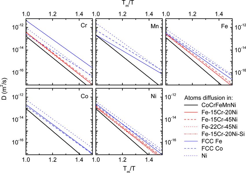
High Entropy Alloys: Breakthrough Materials
        for Aero Engine Applications?

                                             by

                               DANIEL O. SVENSSON

                                Diploma work 2014
              at Department of Materials and Manufacturing Technology
                  CHALMERS UNIVERSITY OF TECHNOLOGY
                               Gothenburg, Sweden

Diploma work in the Master programme Applied Physics

Performed at:             GKN Aerospace Sweden AB
                          Flygmotorvägen 1, 461 38 Trollhättan

Supervisor:               Ph.D., Adj. Associate Professor Magnus Hörnqvist
                          GKN Aerospace Sweden AB
                          Flygmotorvägen 1, 461 38 Trollhättan

Examiner and supervisor: Assistant Professor Sheng Guo
                         Department of Materials and Manufacturing Technology
                         Chalmers University of Technology, SE - 412 96 Gothenburg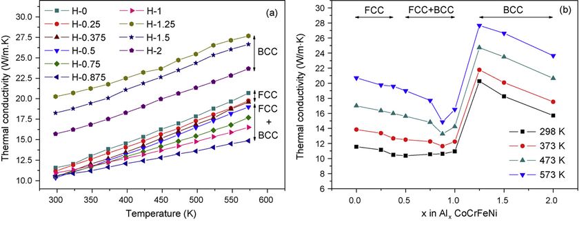
High Entropy Alloys: Breakthrough Materials for Aero Engine Applications? DANIEL O. SVENSSON © DANIEL O. SVENSSON, 2015. Diploma work 2014 Department of Materials and Manufacturing Technology Chalmers University of Technology SE412 96 Gothenburg Sweden Telephone + 46 (0)31772 1000 Cover: [Schematic illustration of BCC crystal structure: (top) perfect lattice (take Cr as example); (middle) distorted lattice caused by additional one component with different atomic radius (take CrV solid solution as example); (bottom) serious distorted lattice caused by many kinds of differentsized atoms randomly distributed in the crystal lattice with the same probability to occupy the lattice sites in multicomponent solid solutions (take AlCoCrFeNiTi0.5 as example) [1].] Gothenburg, Sweden 2015
High Entropy Alloys: Breakthrough Materials for Aero Engine Applications? DANIEL O. SVENSSON Department of Materials and Manufacturing Technology Chalmers University of Technology SUMMARY In this project the current literature regarding a relatively new materials type, highentropy alloys (HEAs), was reviewed to find if they are applicable to aero engines, and in particular the engine parts made by GKN Aero Engine Systems in Trollhättan. To manage this the current stateoftheart of aero engine materials was reviewed as well, partly via a literature survey and partly via discussions with company specialists at GKN Aero Engine Systems in Trollhättan. Based on these two reviews, several issues requiring further studies for future researchers to fill in the gap was identified, with possible solutions suggested where possible, and finally possible HEA systems were suggested for use in the specific engine parts manufactured by GKN Aero Engine Systems. Keywords: Highentropy alloys, high entropy effect, aeropropulsion, high temperature structural materials.
Acknowledgements
    The author wishes to thank Magnus Hörnqvist and Sheng Guo at Chalmers Univer-
sity of Technology for their help and supervision during this project. Aside from these,
the help from Anders Hellgren, and Bengt Pettersson, GKN Aerospace Engine Systems
Sweden regarding the properties of specific parts is greatly appreciated.

                                              Daniel Svensson, Gothenburg 2015-01-09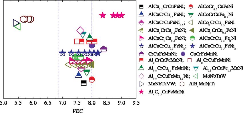
Acronym/Symbol   Meaning
δ                Atomic Size Difference
κ                Thermal Conductivity
ρ                Density
A                Atomic Weight
CT E             Coefficient of Thermal Expansion
E                Modulus of Elasticity
G                Gibbs Free Energy
H                Enthalpy
S                Entropy
T                Temperature
Tm               Melting Temperature
V EC             Valence Electron Concentration
X                Atomic Fraction
AM               Additive Manufacturing
CMC              Ceramic Matrix Composite
HCF              High Cycle Fatigue
HEA              High-Entropy Alloy
HPC              High Pressure Compressor
HPT              High Pressure Turbine
HV               Vickers Hardness
LCF              Low Cycle Fatigue
LCS              Load Carrying Structure
LPC              Low Pressure Compressor
LPT              Low Pressure Turbine
MA               Mechanical Alloying
MTF              Mid Turbine Frame
PM               Powder Metallurgy
TBC              Thermal Barrier Coating
TBH              Tail Bearing Housing (see also TEC, TRF)
TEC              Turbine Exhaust Case (see also TBH, TRF)
TRF              Turbine Rear Frame (see also TBH, TEC)
UTS              Ultimate Tensile Strength
YS               Yield Strength
Contents
1 Introduction 1
2 State-of-the-Art of Aero Engine Materials 3
2.1 The Jet Engine . . . . . . . . . . . . . . . . . . . . . . . . . . . . . . . . . 3
2.2 Materials in Jet Engines . . . . . . . . . . . . . . . . . . . . . . . . . . . . 5
2.2.1 Aluminium Alloys . . . . . . . . . . . . . . . . . . . . . . . . . . . 5
2.2.2 Steels . . . . . . . . . . . . . . . . . . . . . . . . . . . . . . . . . . 5
2.2.3 Titanium Alloys . . . . . . . . . . . . . . . . . . . . . . . . . . . . 5
2.2.4 Nickel-based Alloys . . . . . . . . . . . . . . . . . . . . . . . . . . . 7
2.2.5 Newer Material Types . . . . . . . . . . . . . . . . . . . . . . . . . 9
2.3 Coatings in Jet Engines . . . . . . . . . . . . . . . . . . . . . . . . . . . . 11
2.4 Specific Parts . . . . . . . . . . . . . . . . . . . . . . . . . . . . . . . . . . 12
2.4.1 Turbine Exhaust Case . . . . . . . . . . . . . . . . . . . . . . . . . 13
2.4.2 Mid Turbine Frame . . . . . . . . . . . . . . . . . . . . . . . . . . 14
2.4.3 Nozzle and Exhaust Cone . . . . . . . . . . . . . . . . . . . . . . . 15
3 High-Entropy Alloys 18
3.1 Introduction to HEAs . . . . . . . . . . . . . . . . . . . . . . . . . . . . . 18
3.1.1 Definition . . . . . . . . . . . . . . . . . . . . . . . . . . . . . . . . 18
3.1.2 Phases in HEAs . . . . . . . . . . . . . . . . . . . . . . . . . . . . 20
3.2 Reasons for Properties . . . . . . . . . . . . . . . . . . . . . . . . . . . . . 22
3.2.1 High Mixing Entropy . . . . . . . . . . . . . . . . . . . . . . . . . 22
3.2.2 Sluggish Diffusion . . . . . . . . . . . . . . . . . . . . . . . . . . . 22
3.2.3 Lattice Distortion . . . . . . . . . . . . . . . . . . . . . . . . . . . 24
3.2.4 Cocktail Effect . . . . . . . . . . . . . . . . . . . . . . . . . . . . . 24
3.3 Typical Properties . . . . . . . . . . . . . . . . . . . . . . . . . . . . . . . 25
3.3.1 Room Temperature Strength . . . . . . . . . . . . . . . . . . . . . 26
3.3.2 Elevated Temperature Strength . . . . . . . . . . . . . . . . . . . . 29
3.3.3 Wear Resistance . . . . . . . . . . . . . . . . . . . . . . . . . . . . 33
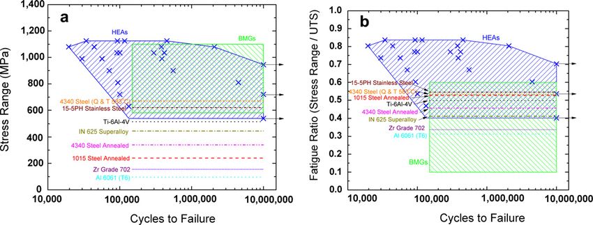
3.3.4 Fatigue Properties . . . . . . . . . . . . . . . . . . . . . . . . . . . 33
i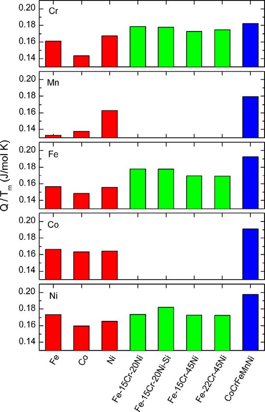
CONTENTS

         3.3.5 Corrosion . . . . . . . . . . . . . . .               . . . . . .             .   .   .   .   .   .   .   .   .   .   .   34
         3.3.6 Oxidation . . . . . . . . . . . . . . .               . . . . . .             .   .   .   .   .   .   .   .   .   .   .   36
         3.3.7 Thermal Properties . . . . . . . . .                  . . . . . .             .   .   .   .   .   .   .   .   .   .   .   36
         3.3.8 Magnetic and Electric Properties . .                  . . . . . .             .   .   .   .   .   .   .   .   .   .   .   39
   3.4   Processing of HEAs . . . . . . . . . . . . .                . . . . . .             .   .   .   .   .   .   .   .   .   .   .   40
   3.5   Motivations for Using HEAs as Aero Engine                   Materials               .   .   .   .   .   .   .   .   .   .   .   41

4 Bridging the Gap                                                                                                                       45
  4.1 Creep and Fatigue . . . . . . . .     .    .   .   .   .   .   .   .   .   .   .   .   .   .   .   .   .   .   .   .   .   .   .   46
  4.2 Oxidation . . . . . . . . . . . . .   .    .   .   .   .   .   .   .   .   .   .   .   .   .   .   .   .   .   .   .   .   .   .   46
  4.3 Thermal Properties . . . . . . . .    .    .   .   .   .   .   .   .   .   .   .   .   .   .   .   .   .   .   .   .   .   .   .   47
  4.4 Property and Alloy Optimization       .    .   .   .   .   .   .   .   .   .   .   .   .   .   .   .   .   .   .   .   .   .   .   47
  4.5 Manufacturability . . . . . . . .     .    .   .   .   .   .   .   .   .   .   .   .   .   .   .   .   .   .   .   .   .   .   .   48

5 Summary and Future Prospects                                                                                                           49
  5.1 Summary . . . . . . . . . . . . . . . .            .   .   .   .   .   .   .   .   .   .   .   .   .   .   .   .   .   .   .   .   49
  5.2 Future Prospects in Aero Engine Parts              .   .   .   .   .   .   .   .   .   .   .   .   .   .   .   .   .   .   .   .   50
      5.2.1 Structural Components . . . .                .   .   .   .   .   .   .   .   .   .   .   .   .   .   .   .   .   .   .   .   51
      5.2.2 Heat Shields . . . . . . . . . .             .   .   .   .   .   .   .   .   .   .   .   .   .   .   .   .   .   .   .   .   52
      5.2.3 Nozzle and Cone . . . . . . . .              .   .   .   .   .   .   .   .   .   .   .   .   .   .   .   .   .   .   .   .   54

    Bibliography                                                                                                                         55

                                            ii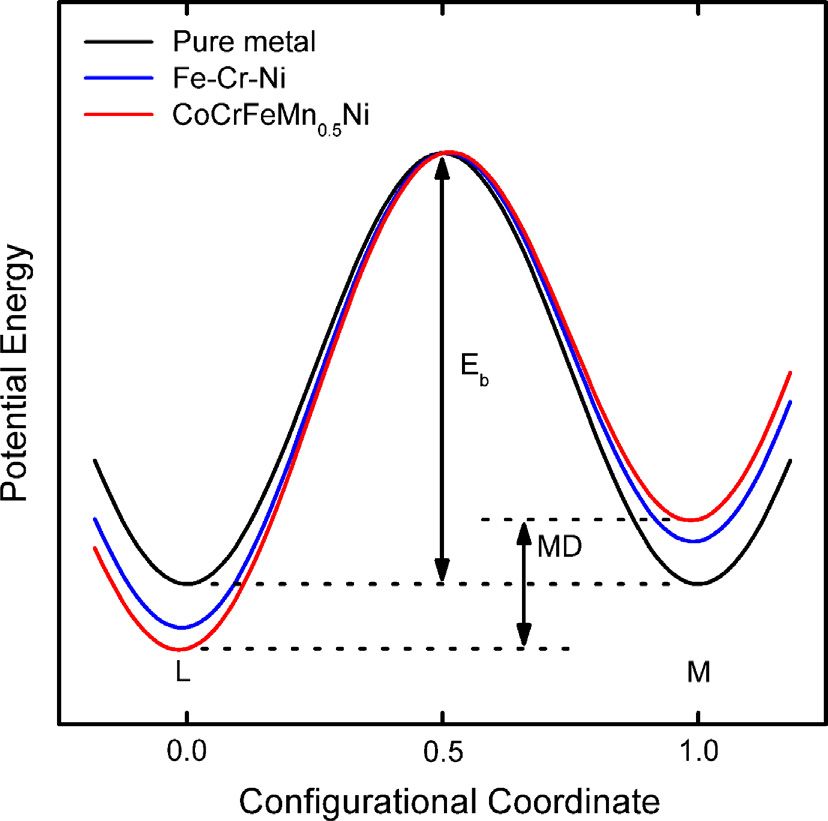
1
                            Introduction

T
         he aero engine industry is ever changing, with new materials and techniques
          being developed continuously to be able to meet both the demands of passen-
          gers and government regulations. The engines produce less and less noice and
          use less and less fuel, reducing emissions more and more. One of the more
effective ways to reduce fuel consumption is to lower the total weight of the engine, for
instance by replacing the current materials with lighter ones. Other possibilities is to
raise the working temperature of the engine (increasing the demands on the materials in
the engine) or improving the design of the engine itself, turbines, compressors, fans etc.
    At GKN Aerospace Engine Systems in Trollhättan, several engine parts for different
aero (jet) engines are manufactured, some of which GKN has the design responsibility
for and some of which are just manufactured at GKN according to instructions. For the
parts which they have the design responsibility for they are always looking for possible
improvements, and here the so called high-entropy alloys (HEAs) are very interesting.
At the moment mainly due to their potential for lower densities than conventional high-
temperature alloys (such as the currently used superalloys) as well as their generally
good properties at elevated temperatures, with good softening resistance.
    HEAs are alloys consisting of between five and thirteen principal components (com-
ponents with a larger concentration), as opposed to conventional alloys which have at
most three principal components. This gives rise to many promising properties, based
mostly on what is known as the four core effects. These core effects are a high entropy
of mixing, a slower diffusion than in conventional alloy systems, an increased lattice
strain (due to the many differently sized elements) and finally a cocktail effect, leading
to properties that at first may seem unintuitive. These effects and the properties they
lead to will be discussed more in the following chapters.
    This thesis is done together with GKN Aerospace Engine Systems in Trollhättan, and
its purpose is to review what is known about HEAs today and, if possible, to suggest
potential usages in aero engines, including both specific aero engine parts and promising

                                            1
CHAPTER 1. INTRODUCTION
HEA systems. The aim is also to review the current status of materials in jet engines,
which is covered in Chapter 2, while Chapter 3 will contain a review to some relevant
developments in HEAs. These two reviews will be followed by Chapter 4, describing
what is missing for HEAs to be able to work in jet engines, and finally Chapter 5,
summarizing HEAs and their potential usage in aero engines.
22
State-of-the-Art of Aero Engine
Materials
T
oday’s aero engines are composed of different materials, Figure 2.1 shows a typi-
cal material distribution for a jet engine, and as can be seen it consists mostly of
nickel alloys and titanium alloys along with some steels and aluminium alloys.
The choice of alloys for different parts is heavily dependent on the working
temperature and mechanical demands of the specific part along with the density of the
alloy. An ideal alloy would be able to handle extreme temperatures while weighing next
to nothing. This chapter will first give a simple description of how a jet engine works,
followed by an introduction to the current materials in today’s jet engines, with a brief
description of aluminium alloys and steels and a more detailed description of titanium
alloys and nickel alloys, since these are the alloys which are most commonly used in aero
engines. A short introduction to some other new and promising types of material will
also be given, including composites, ceramics and intermetallics. This will be followed
by a description of the relevant specific parts in the aero engine, and the demands on
these parts.
2.1 The Jet Engine
The jet engine basically works in four simple steps, suck, squeeze, bang and blow.
During the suck stage air from outside of the engine enters at great volumes. The air
is then squeezed together and mixed with fuel, and, following this, the fuel/compressed
air mix is ignited at a constant pressure (bang), forcing the gas to expand through a
turbine which then powers the compressor responsible for squeezing the air and then
continuing further out of the engine (blow). It is normal to use between one and three
compressors (often two), driven by separate turbines. According to Newton’s third law
”when one body exerts a force on a second body, the second body simultaneously exerts
3CHAPTER 2. STATE-OF-THE-ART OF
2.1. THE JET ENGINE
AERO ENGINE MATERIALS
Figure 2.1: Typical material distribution of a jet engine [2].
a force equal in magnitude and opposite in direction on the first body”, and with these
great magnitudes of air molecules forced ”backwards” at high speed a forward thrust for
the engine is generated.
In military versions of the jet engine there is often an afterburner after the turbine
exhaust where additional fuel may be injected and the stream again ignited. A more
common version of the jet engine for civilian use is the turbofan jet engine, where at the
front there is a large fan driven by one turbine which draws in and compresses air, partly
into the core engine going through the stages outlined previously, and partly bypassing
the core engine, contributing directly to the thrust. This is the type of engine seen in
Figure 2.1. The version without the fan is called a turbojet.
That this procedure leads to elevated temperatures is easy to understand. First there
is a rise in temperature when the air is compressed, the more compressed the higher the
temperature, and with ignition this temperature is then again increased putting great
demands on the combustion chamber and all parts downstream, especially so on the
combustion chamber and the first turbine, but as work is extracted it is cooled down a
bit to the next turbine.
4CHAPTER 2. STATE-OF-THE-ART OF
2.2. MATERIALS IN JET ENGINES
AERO ENGINE MATERIALS
2.2 Materials in Jet Engines
With different parts in the jet engine having different demands and limiting prop-
erties, many different materials are in use, though most of them stem from four major
families, and these are aluminium alloys, steels, titanium alloys and nickel alloys. Out-
side of these four major material types there is also research and development being done
on newer material types such as ceramics, composites and intermetallics. Each of these
types of material will be described in this section, with the major focus on Ti-alloys and
Ni-alloys, the most common materials in the jet engine today.
2.2.1 Aluminium Alloys
Aluminium alloys have among the lowest densities of the alloys in use in aero en-
gines, with pure aluminium having a density of 2.7 g/cm3 [3]. They also show excellent
fabricability and corrosion resistance [4]. Unfortunately, at elevated temperatures they
loose some of their strength properties. The temperature limits are ≈ 200 - 250◦ C for a
short time or ≈ 120 - 150◦ C for long-term usage [4], which is nothing compared to the
≈ 1500 ◦ C which may be reached in, as well as downstream of, the combustion chamber
in a jet engine [5]. It also has a lower modulus of elasticity than for instance steels and
titanium alloys (69 GPa versus 200 GPa and 110 GPa [3], respectivley). Typical alloys
used in jet engines are 2xxx, 6xxx and 7xxx-series wrought alloys and 3xx-series cast
alloys.
2.2.2 Steels
The main advantage of steels is often their price, steels being based on iron and
carbon which are two of the cheapest elements. Steels typically used in jet engines are:
low alloy high strength steels (in shafts and gears bearings), austenitic stainless steels
(in tubings) as well as martensitic and precipitation hardening steels (in frames and
casings).
2.2.3 Titanium Alloys
Titanium alloys have a high strength-to-weight ratio, good fatigue strength, better
corrosion resistance than both aluminium and steel alloys and they can work at higher
temperatures than aluminium alloys (up to 600◦ C) [6, 7, 8]. Titanium exists in two
different crystalline forms, the hexagonal close packed (hcp) α phase, which is stable
at lower temperatures, and the body-centered cubic (bcc) β phase which is stable at
elevated temperatures, from ≈ 880◦ C to the melting point. This solvus temperature
can be changed with alloying elements, giving great configurability of the properties of
titanium alloys.
Titanium alloys (some of which can be seen with some basic mechanical properties
given in Table 2.1) are divided into four classes depending on the ratio of α and β
phases at room temperature. The classes are 1) α and 2) near α, which consists of
5CHAPTER 2. STATE-OF-THE-ART OF
2.2. MATERIALS IN JET ENGINES
AERO ENGINE MATERIALS
Table 2.1: Mechanical properties of some titanium alloys. [9]
Alloy Density Yld.Str. Tens.Str. 107 Cyc. Fat. Str.
(g/cm3 ) (MPa) (MPa) (MPa)
Commercially Pure 4.51 351 483 244
Ti-6%Al-4%V 4.42 911 999 609
Ti-4%Al-4%Mo-2%Sn-0.5%Si 4.60 1035 1136 626
Ti-10%V-2%Fe-3%Al 4.65 1228 1311 721
Ti-6%Al-2%Sn-4%Zr-2%Mo 4.54 917 1012 558
mostly the α phase, where the alloys usually have ≈ 5 − 6% Al along with some Sn and
Zr for solid solution strengthening as well as some β phase stabilizers. These alloys have
good elevated temperature properties, with good creep resistance and strength retaining.
There are also 3) α/β alloys, which have sizable portions of both α and β phases. These
have the best balance of mechanical properties. The most common titanium alloy, Ti-
6Al-4V, which accounts for about 60% of all produced titanium alloys [7], is this type
of alloy. They have good room temperature properties and good elevated temperature
properties for short amounts of time. The last class is 4) metastable β, which shows high
deformability, but also high density and reduced ductility when heat treated to peak
strength levels.
The properties of Ti alloys make them suitable for the cooler parts of the engine.
It is commonly used in the fan disk, where the limiting properties are low cycle fatigue
(LCF) and fatigue crack growth. Common alloys in this scenario are Ti-6Al-4V, Ti-
5Al-2Zr-2Sn-4Cr-4Mo and Ti-6Al-2Sn-4Zr-6Mo. Another common area of use is in the
compressor rotor (both low pressure compressor (LPC) and high pressure compressor
(HPC) rotor), which can have up to seven stages, where the first stages often are limited
by LCF and the last stages are limited by creep. The most common alloy for the front
stages is Ti-6Al-4V and the most common for the back stages is Ti-6Al-2Sn-4Zr-2Mo+Si
(for the HPC the final stages are exposed to temperatures too high for the titanium alloys
and are instead made of nickel-based alloys). The fan blades and between six and eight
stages of the compressor air foils are also ordinarily Ti alloys, most often Ti-6Al-4V.
These are limited by high cycle fatigue (HCF), but also by their resistance to impact
damage from foreign objects. Ideally higher-strength alloys would be used, but those are
often too difficult to fabricate. There are also many static components made of titanium
alloys such as frames, casings etc. [8] A problem however is their relatively low stiffness,
as mentioned in section 2.2.1
Titanium alloys are also used in structural parts and casings in the cooler parts of the
engine, for instance in the intermediate compressor casing (ICC), which consists mostly
out of Ti-6Al-44 and Ti-6Al-2Sn-4Zr-2Mo.
6CHAPTER 2. STATE-OF-THE-ART OF
2.2. MATERIALS IN JET ENGINES
AERO ENGINE MATERIALS
2.2.4 Nickel-based Alloys
When the temperature is too high for titanium alloys (≥ 550 ◦ C), the most common
replacement is the nickel-based superalloys (so named due to their superior properties
compared to ordinary alloys). These alloys show high strength, good fatigue and creep
resistance along with good corrosion resistance. They are also able to sustain these
properties over extended periods of time at higher temperatures. Of the total engine
weight about half is due to these superalloys [2, 8, 10]. Aside from the nickel based
superalloys, there are also nickel-iron based and cobalt based superalloys, but since most
of the superalloys in a jet engine is nickel-based or nickel/iron-based they will be the
focus of this section.
Nickel-based superalloys have a face centered cubic (fcc) austenite γ matrix and get
their strength from a combination of solid solution hardening, precipitation hardening
with γ � and γ �� phases as well as a presence of carbides at the grain boundaries. Many
different elements are added to the matrix to achieve the sought after properties of these
materials, and the most common ones and their purpose can be seen in Table 2.2.
Table 2.2: Role of alloying elements in superalloys. [2, 11]
Alloy Solid Solution γ� Carbide Grain Boundary Oxide Scale
additions Strengtheners Formers Formers Strengtheners Formers
Chromium x x x
Aluminium x x
Titanium x x
Cobalt x
Molybdenum x x
Tungsten x x
Boron x
Zirconium x
Carbon x
Niobium x x
Hafnium x x
Tantalum x x x
The γ � formers are responsible for the precipitation hardening, especially so Al and
to some extent Ti, which together with Ni form the fcc ordered Ni3 (Al,Ti) γ � phase.
This phase only has a 0.1% lattice mismatch with the γ matrix, giving it a long term
stability, and a typical microstructure can be seen in Figure 2.2. There are also nickel
alloys with other precipitate phases for strengthening, for instance adding niobium to
nickel creates the γ �� Ni3 Nb precipitates which is one of the strengthening methods in
7CHAPTER 2. STATE-OF-THE-ART OF
2.2. MATERIALS IN JET ENGINES
AERO ENGINE MATERIALS
Figure 2.2: The γ matrix with γ � precipitates. [12]
Figure 2.3: Material used in General Electric Aero Engines rotating and structural forgings
for the year 2000 (all materials except those made by PM were made by casting). [13]
the nickel/iron alloy Inconel 718, which is by far the most used superalloy (Figure 2.3
shows the materials used by GE aviation in the year 2000, where Inconel 718 was the
most used material).
As mentioned earlier the nickel based alloys are most often the material of choice in
the hotter parts of the engines (this despite their relatively high density), such as the
last stages of the HPC, the high pressure turbine (HPT) and the low pressure turbine
8CHAPTER 2. STATE-OF-THE-ART OF
2.2. MATERIALS IN JET ENGINES
AERO ENGINE MATERIALS
(LPT). Here LCF life and fatigue crack growth are limiting properties [2]. For the air
foils in the HPT, oxidation resistance is also an important property for the material [8].
The turbine disks have often been made of Inconel 718 [14], but alloys manufactured via
powder metallurgy (PM) processing has also been used with alloys like LC Astroloy1
and Rene952 [14]. There are several reasons for choosing PM over conventional casting,
including: it minimizes the segregation of elements making the alloys more homogeneous;
some alloys cannot be forged by conventional methods; it can to a greater extent be made
to certain shapes, reducing the need for machining and raw materials, along with other
benefits.
For parts where creep resistance is of extreme importance, such as the turbine blades
in the early part of the turbine, the parts may be cast as single crystals using alloys such
as CMSX43 , DMS44 and TMS1965 (able to withstand temperatures up to ≈ 1140 ◦ C
[14]), removing high-angle grain boundaries and thus removing creep arising from grain
boundary sliding [8, 10]. This also removes the necessity for grain boundary strength-
ening elements in the alloy. Generally it has been that when creating new generations
of single crystal superalloys with improved creep resistance the density has increased.
This is attributed to the increase of refractory elements and decrease of chromium in
the newer generations [15, 16]. New lower density single crystal superalloys is being
researched however, with densities in the vicinity of 8.5 g/cm3 [15].
Since it is rather expensive to cast single crystals, parts where the creep resistance is
not quite as important (but still important) such as in the blades of the later, somewhat
colder parts of the HPT and in the LPT it may be enough with directionally solidified
alloys (alloys cast with the grain boundaries in parallel with the direction of the load)
such as PWA14226 and DMD47 [14] since these are cheaper [10]. Vanes, having to face
long periods of time at elevated temperatures have often been made by oxide dispersion
strengthened superalloys, such as MA7548 [14].
2.2.5 Newer Material Types
Some newer material types currently being researched will be briefly described in this
section, ceramics, intermetallics and composites (such as ceramic matrix composites).
Ceramics
The excellent heat resisting properties of ceramic materials such as Al2 O3 and SiC
make them interesting for the hotter parts of the engine. They are also lighter and
cheaper than the superalloys relevant for the same parts (up to 40 % lighter and cost
1
56.5Ni15Cr15Co5.25Mo3.5Ti4.4Al0.06C0.03B0.06Zr
2
61Ni14Cr8Co3.5Mo3.5W3.5Nb2.5Ti3.5Al0.16C0.01B0.05Zr
3
61.7Ni6.5Cr9Co0.6Mo6W3Re6.5Ta0.1Hf1Ti5.6Al
4
67Ni2.4Cr4Co5.5W6.5Re9Ta0.1Hf0.3Nb5.2Al
5
59.7Ni4.6Cr5.6Co2.4Mo5.0W6.4Re5.6Ta0.1Hf5.6Al5.0Ru
6
59.2Ni9Cr10Co12W1.5Hf1Nb2Ti5Al0.1Zr0.14C0.015B
7
66.8Ni2.4Cr4Co5.5W6.5Re8Ta1.2Hf0.3Nb5.2Al0.07C0.01B
8
78Ni20Cr1Fe0.05C0.3Al0.5Ti0.6Y2 O3
9CHAPTER 2. STATE-OF-THE-ART OF
2.2. MATERIALS IN JET ENGINES
AERO ENGINE MATERIALS
only 5 % of what superalloys do [14]). As will be mentioned in section 2.3, ceramics
are often used as coatings for parts exposed to high temperatures. Manufacturing whole
parts out of ceramics is not currently viable however, due to their brittleness, and today
they are mostly used in coatings.
Composites
Several types of composites are interesting for the aerospace engine industry. There
are several types of composites, for instance Ti-MMC, which has SiC fibers in a Ti-
matrix. If the problem with properties degradation from fibre-matrix interaction in
Ti-MMCs can be solved they are also very interesting for further aero engine usage,
since they could be used in a bladed ring as opposed to the traditional disc and dove-
tail arrangement, reducing the weight by ≈ 70%. For colder sections polymer matrix
composites such as epoxy resin-carbon fiber composites are currently being used, the
aforementioned composite is for instance used by GE in its front fan blades, thus reduc-
ing their weight as compared with metal-based turbine blades. [14]
There is also ceramic matrix composites (CMCs), with their excellent fracture tough-
ness [17] and possibility to withstand temperatures up to 1500 ◦ C [18] along with their
low densities, making them promising for usage in aero engines. The high temperature
limit means that air cooling is not quite as necessary as it is with superalloys, meaning
great design gains can be made. The most common CMCs use SiC-matrices, with vary-
ing fibers dependant on applications, often it is SiC-fibers or just carbon [14, 17, 18], but
Al2 O3 /Al2 O3 is also common. There are however still some issues with the durability,
reliability, manufacturing, design and cost [14, 18], and CMCs have mostly been tried in
non-rotating parts such as exhaust nozzles on military engines (where a weight saving
of ≈ 50% was gained [18]), afterburner components, combustion chambers and turbine
nozzle vanes [14, 17, 18].
Intermetallics
Certain intermetallics have been of interest for aero engine usage. The most re-
searched intermetallics are based on aluminium together with either titanium or nickel,
with the most focus on γ TiAl and β NiAl. These alloys have a rather low density com-
pared to the usual superalloys, mainly due to their large fractions of aluminium. The
high aluminium content also leads to good oxidation properties. As intermetallics their
ordered structure gives them a rather high melting point and they have comparatively
good creep properties, however only in specific temperature intervals [14, 19]. They do
have quite a lot of drawbacks however, including (but not limited to) the high sensitivity
of the properties on the composition (since the intermetallic phase needs to form), a
certain brittleness at temperatures below 650 ◦ C for γ TiAl and 1000 ◦ C for β NiAl [19].
The brittleness also leads to poor manufacturing properties [19].
So far, even though it should be rather fitting for turbine parts exposed to tempera-
tures of 1100 − 1600 ◦ C, the β NiAl is not used anywhere, mostly due to the aforemen-
tioned poor manufacturability properties and its brittleness [19]. γ TiAl has had a bit
10CHAPTER 2. STATE-OF-THE-ART OF
2.3. COATINGS IN JET ENGINES
AERO ENGINE MATERIALS
more research and development done, and currently we are in the third generation of
γ TiAl based alloys, which are able to withstand temperatures from room temperature
up to 850 ◦ C, making LP compressor components a possible application. The second
generation γ TiAl alloys have a temperature range of 650 − 750 ◦ C and since they also
have good HCF properties they are interesting for blades and shrouds of the HP com-
pressor, where a possible weight saving of 20% was expected [19]. There was in fact
successful demonstration programs for among other parts LPT turbine blades as well as
HP compressor blades and shrouds [19].
There are still however rather large problems with these materials, with for instance
a large scattering in mechanical properties, a low tolerance to defects, comparatively
high production costs and manufacturing difficulties [14, 19]. These problems are not
final though, and for instance GE is using γ TiAl for LPT blades in their engines [20]. As
a curiosity when talking about the development of new materials it can be said that the
research and development costs for GE regarding γ TiAl is calculated to ≈ $40 million,
with additional costs of > $85 million to industrialize it for turbine blades [21].
2.3 Coatings in Jet Engines
Another way to make the materials able to withstand the different environments is to
coat them with a protective layer. There are basically three types of coatings today, one
type of which are aluminide coatings (also known as diffusion coatings) which are meant
to protect against oxidation by creating an aluminide layer (CoAl or β-NiAl) by letting
aluminium react with the nickel or cobalt in the base metal. There are also overlay
coatings, which are coatings where all of the elements comes from the coating itself,
with no elements coming from the substrate, and here the thickness is not as dependant
on processing conditions. Overlay coatings are most often of the form MCrAlY, where
M is either iron, nickel, cobalt or a combination. These often have improved corrosion
resistance, much due to the effect of yttrium. WC-Co is another type of coating, which
is used mostly at parts susceptible to wear due to the high hardness of the coating.
Third, we have thermal barrier coatings (TBC), which as the name suggests are
used to make the substrate materials able to operate at higher temperatures than they
normally do, and they can lower the surface temperature of the relevant superalloys by
100 − 200 ◦ C [5, 22]. TBCs are most often based on the ceramic Y2 O3 -stabilized ZrO2 ,
which has a very low thermal conductivity at elevated temperatures (≈ 2.3 W/mK at
1000 ◦ C [22]) and a high coefficient of thermal expansion (11·10−6 ◦ C−1 [22]) allowing it to
alleviate stresses from the mismatch between the ceramic and the underlying metal. The
so-called misfit strain arising from differences in thermal expansion is one of the limiting
properties durability-wise during the thermal cycles and must therefore be managed [23].
Sought after properties of TBCs are low thermal conductivity and stability during the
thermal cycles along with resistance to erosion and pollutants [5]. There are several
factors contributing to the thermal conductivity of coatings: the density of the coating,
the number of internal boundaries and pores. These along with the orientation of the
internal cracks and pores relative to the thermal flux are the major contributors and will
11CHAPTER 2. STATE-OF-THE-ART OF
2.4. SPECIFIC PARTS
AERO ENGINE MATERIALS
Figure 2.4: Schematic of a TBC on an air-cooled gas turbine engine component. [24]
have to be controlled for as effective TBCs as possible [5].
TBCs are applied above an overlay coating of MCrAlY or on an aluminide coating
which is for the oxidation resistance along with providing a rough enough surface for
the TBC to bond to. Figure 2.4 gives a description of the different layers in a TBC.
TBCs are often used in applications like nozzle guide vanes and blade platforms [14]. If
one were to find a TBC with among other things a coefficient of thermal expansion that
matches that of the substrate material, it would not only be a shielding coating but also
a load bearing one, giving another use to the coating.
2.4 Specific Parts
Choosing the specific parts which at first will be relevant for HEAs two major fac-
tors was identified. Firstly, that HEAs shows great potential for relatively low densities.
Perhaps not lower than titanium alloys but still lower than nickel based superalloys. Sec-
ondly, they show great promise for high temperature stability. These properties (which
will be discussed more in Chapter 3) indicate that HEAs could be potential replacement
materials for the hotter structural components downstream of the combustion chamber,
such as the turbine exhaust case and the mid turbine frame, but also the turbine exit
(nozzle and cone) as these parts today are composed mainly out of the relatively heavy
nickel alloys, while the cold structural parts are made out of lighter elements such as
12CHAPTER 2. STATE-OF-THE-ART OF
2.4. SPECIFIC PARTS
AERO ENGINE MATERIALS
Figure 2.5: Simple sketch of a TEC. [25]
titanium alloys. These hot structural parts will therefore be described in more detail in
this section.
2.4.1 Turbine Exhaust Case
After (downstream of) the final turbine in the jet engine one finds the turbine exhaust
case, also known as the turbine rear frame or the tail bearing housing. The purpose of
this part is to support the end of the LP rotor, mount the engine to the aircraft body
as well as to remove the angular component of the outgoing flow. Figure 2.5 shows the
main components of the TEC, the inner and outer rings as well as the vanes.
While the temperatures of the gas in the TEC is not quite as high as in the turbines
due to work being extracted from the gas it still have to face rather high temperatures and
it thus must be able to retain some of its mechanical properties to continue its function
as engine mount. It also need to be corrosion and oxidation resistant at these elevated
temperatures, while being weldable, formable and generally malleable. Unfortunately it
is not sufficient to just have these properties. The materials used in the TEC must also
be fatigue resistant (primarily LCF), not too heavy, weldable, malleable, and generally
able to shape and join. Today Inconel 718 is the most used alloy in the TEC, being able
to face temperatures of ≈ 650 ◦ C.
Another reason for the importance of weldability, other than for the joining of differ-
ent parts, is that it is related to and opens up the door (or rather keeps the door open)
for additive manufacturing (a form of 3D-printing). This is a technique that in the future
could be a material saver, for instance when having extending parts on a circular disk
13CHAPTER 2. STATE-OF-THE-ART OF
2.4. SPECIFIC PARTS
AERO ENGINE MATERIALS
Figure 2.6: Sketch of separation of functionality in TEC and MTF, with supporting ma-
terial (LCS) inside heat shielding fairings in the flow path.
these parts can be added layer by layer. This instead of starting from a disk of a wider
diameter and then machining away the unwanted material which leads to quite a waste
of materials.
One possible change in the layout of the TEC is to separate the functionality of
the vanes, with a supporting structure inside heat shield fairings made of some solu-
tion hardened alloy (see Figure 2.6 for a simple sketch). The heat shield materials are
preferably solution hardened since these types of alloys does not loose their properties
as easily as precipitation hardened alloys at increased temperatures and since they are
easy to process. The limiting properties for the load carrying structure (LCS) inside
the fairings is primarily LCF properties, followed by strength, stiffness, creep/thermo
mechanical fatigue and oxidation properties, and the primary alloy for this is today In-
conel 718. Also, with LCSs, an elongation at fracture of at least 5% is wanted. The
materials for heat shielding fairings are limited primarily by their temperature capability
(e.g. thermal stability, creep deformation), followed by their formability and oxidation
properties. The working temperatures for the heat shields are expected to be ≈ 670 ◦ C
with peak temperatures of ≈ 760 ◦ C. It is expected though that in the future these
temperatures may reach as high as ≈ 900 ◦ C with average temperatures of ≈ 800 ◦ C.
The composition of some typical precipitation hardened and solution hardened al-
loys can be seen in Table 2.3, and some describing parameters for the aforementioned
properties and typical alloys can be seen in Table 2.4.
2.4.2 Mid Turbine Frame
Upstream of the TEC in the engine, between the high pressure and low pressure
turbines, is the mid turbine frame (MTF), which can be seen in Figure 2.7. This houses
14CHAPTER 2. STATE-OF-THE-ART OF
2.4. SPECIFIC PARTS
AERO ENGINE MATERIALS
Figure 2.7: Model of a generic MTF.
the mid turbine bearing supporting the HP and LP rotors and transmits their loads to
the outer casing. The demands on the MTF are somewhat similar to the demands on
the TEC, but since the MTF is situated before the low pressure turbine the temperature
of the gas is a bit higher. It needs to have a certain stiffness to make sure that the blade
tips are able to rotate without being hindered by the casings, something which must be
true during both normal flight and more extreme maneuvers. The MTF is today mostly
made out of nickel alloys, which is due to the aforementioned high temperatures.
The MTF normally has a separation of functionalities as described in the previous
section, with vanes composed of a LCS protected by a heat shielding fairing. The limiting
properties for the LCS are similar to those of the LCS for the TEC, with primarily LCF
properties, followed by strength and stiffness properties. The most interesting alloy for
this today is again Inconel 718. The alloy choice for the fairings is limited primarily by
their creep strength properties, followed by their oxidation properties and LCF/thermo
mechanical fatigue. The alloys looked at in the present is the Ni-based Mar-M-247 and
the Co-based Mar-M-509.
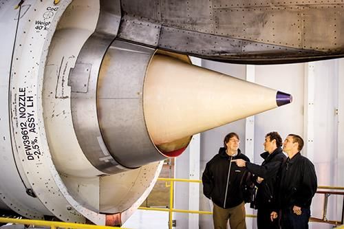
2.4.3 Nozzle and Exhaust Cone
Downstream of the TEC we find the final parts of the (civilian) jet engine, the
nozzle and exhaust cone (in jet engines for military applications there is often also an
15CHAPTER 2. STATE-OF-THE-ART OF
2.4. SPECIFIC PARTS
AERO ENGINE MATERIALS
c Boeing
Figure 2.8: Picture of an exhaust cone and nozzle attached to an aeroplane. �
afterburner), seen in Figure 2.8. The existing cones of today are most often made out of a
titanium alloy, but cones for newer engines are made out of solution hardened superalloys.
The research for future cones today is mostly focused on CMC based on Al2 O3 and SiC.
Limiting properties are among others creep properties, temperature capability, surface
stability and weight (density). If the nozzle and cone could be manufactured together
with the TEC instead of separately, care could be taken to improve the properties of the
interfaces that arise when the three separate parts are assembled together.
162.4. SPECIFIC PARTS
Table 2.3: Composition in weight % for the superalloys Inconel 718 [26], Waspaloy [27] and Haynes 230 [28]. * denotes that the
element is used for balance, ’ denotes that it is the maximum allowed value.
Alloy Ni Co Cr W Mo Fe Mn Si Al C La B Ti Cu Zr Nb+Ta
Inconel 718 50-55 17-21 - 2.8-3.3 * - - 0.2-0.8 - - - 0.65-1.15 - - 4.75-5.5
Waspaloy 58* 13.5 19 - 4.3 2’ 0.1’ 0.15’ 1.5 0.08 - 0.006 3 0.1* 0.05 -
Haynes 230 57* 5’ 22 14 2 3’ 0.5 0.4 0.3 0.1 0.02 0.015’ - - - -
Table 2.4: Key values for some properties for the precipitation hardened conventional alloy Inconel 718 (1/2 inch bar stock),
solution hardened Haynes 230 (sheet) and precipitation hardened Waspaloy (sheet)
Property Inconel 718 Haynes 230 Waspaloy
Density (g/cm3 ) 8.19 [29] 8.97 [28] 8.20 [27]
17
CHAPTER 2. STATE-OF-THE-ART OF
UTS (RT) (MPa) 1375 [29] 860 [28] 1335 [27]
UTS (650◦ C) (MPa) 1100 [29] 670 [28] 1195 [27]
σ0.2 (RT) (MPa) 1100 [29] 390 [28] 910 [27]
σ0.2 (650◦ C) (MPa) 980 [29] 270 [28] 770 [27]
AERO ENGINE MATERIALS
σ0.2 (RT, after 650◦ C exposure for 1000 h) (MPa) - 440 [28] -
� (650◦ C) (%) 25 [29] 55.3 [28] 20.8 [27]
Modulus of elasticity (RT) (GPa) 208 [30] 211 [28] 213 [27]
CTE (RT) (·10−6 K−1 ) 13.0 [29] 12.7 [28] 13.9 [27]
CTE (650◦ C)(·10−6 K−1 ) 15.1 [29] 15 [28] 14.8 [27]
Thermal conductivity (RT) (W/m · K) 11.4 [29] 8.9 [28] -
Thermal conductivity (650◦ C) (W/m · K) - 21.4 [28] 20 [27]
Stress for rupture after 1000h at 650◦ C (MPa) 896 [30] 295 [28] 550 [27]3
High-Entropy Alloys
H
igh-entropy alloys (HEAs) is a rather novel subject with many possible applica-
tions. Even though the concept dates back to the 70s with the work of Cantor
et. al. [31] (or even the late 18th century with studies by Franz Karl Achard
[31]) it was not until 2004 that it really took foot with the discoveries by Yeh
et al. [32]. This opened up a new world for materials scientists and a lot of research has
been done since then. This chapter is aiming to review the current status of HEAs, with
focus on properties relevant for use in aerospace engines. This includes among others,
strength, fatigue, wear and high temperature properties. It will begin with the definition
of HEAs along with typical properties and processing routes. This will be followed by a
closer look at why they are potential materials for use in aerospace engines.
3.1 Introduction to HEAs
This introduction will contain the definition of HEAs. There will also be some dis-
cussions regarding different phases in HEAs along with how they may be predicted.
3.1.1 Definition
A rather simple definition of HEAs is to consider alloys of five or more metallic
elements where each of these elements has a concentration of between 5 and 35% as
HEAs [32]. There can also be elements with a lower concentration than 5%, and these
are called minor elements, as opposed to principal for those in higher ratio. This was
the definition given by Yeh et al. in 2004 [32].
There are however other definitions, and even though the scope of materials is very
similar there are some differences. One main definition is to go by the configurational
entropy of the alloy, and this was proposed by Miracle et al. [33]. This is due to that
one of the major effects of HEAs is their high entropy of mixing ΔSmix , of which the
183.1. INTRODUCTION TO HEAS CHAPTER 3. HIGH-ENTROPY ALLOYS
configurational entropy ΔSconf is a major part. Before going into the definition, the
reasoning for the name high-entropy alloys will be given.
Historically, alloys have consisted of between one and three principal element(s) and
then one or more minor elements, added in small concentrations to change the properties
of the principal element(s). For instance steel, which is based on the principal element
iron with the addition one or more minor elements such as carbon, or the more compli-
cated superalloys discussed in the previous chapter. This is rather severely limited by the
number of existing elements in the periodic table when it comes to the number of pos-
sible systems. Even though the possibility to add more principal elements into the mix
always has existed, there has also been a fear, based on metallurgical knowledge gained
from among other things phase diagrams for ternary alloys, that this would lead to alloys
consisting of several co-existing phases, consisting of among others ordered phases, both
complex intermetallics (intermetallic compounds such as Laves phases) and the more
simple ordered fcc,bcc,hcp-derivations. This high amount of phases would make these
multi-principal component alloys very hard to control.
Surprisingly then, when multi-principal alloys were finally tried, there were mostly
disordered solid solutions, with less compound formation than expected [32]. This is
attributed to the aforementioned high entropy of mixing. It is known that the equilibrium
phase of a system is decided by which phase has the lowest Gibbs free energy,
ΔGmix = ΔHmix − T ΔSmix , (3.1)
where H is the enthalpy, T is the temperature and S is the entropy. From the entropy
part in equation (3.1) we can see that the disordered phases with a high configurational
entropy will gain an advantage over the ordered phases with a lower entropy. This
will help suppress some of the ordered phases (promoted by their negative enthalpies of
mixing), and especially so at higher temperatures.
The configurational entropy per mole for an ideal disordered solution is given by
n
�
ΔSconf = −R Xi ln(Xi ) (3.2)
i
where R is the gas constant (= 8.314 J · (mol · K)−1 ), Xi is the atom fraction of the ith
element and n is the total number of different elements. An ideal solution is a valid
approximation for liquids as well as for solids near their melting temperatures. For
an equimolar alloy (where all elements have the same concentration) with n different
components that means that there is a configurational entropy of S = R ln(n), which
equals to 1.61R when n = 5. Using this, Miracle et al. [33] has defined HEAs to be alloys
with ΔSconf ≥ 1.5R. This does not include all possible combinations from the earlier
definition, according to which the minimum for a 5-element alloy is ΔSconf = 1.36R,
when two components have the ratio 0.35, one has 0.20 and the final two has 0.05, but
other than this they pretty much describe the same systems.
The 1.5R value is chosen since the lower bound for the 5-element alloy is lower than
the equimolar ratio for the 4-element alloy. There are also some conventional alloys
193.1. INTRODUCTION TO HEAS CHAPTER 3. HIGH-ENTROPY ALLOYS
with ΔSconf ≈ 1.36R. It should also be mentioned that for the Miracle definition, there
is some ambiguity since the phase changes with temperature, and one alloy that is a
solid solution above a certain temperature may not be it below. They therefore made
the decision to classify HEAs based on their high temperature configurational entropy.
Using this method they also define low-entropy alloys as those with ΔSconf ≤ 1.0R and
medium-entropy alloys as those with configurational entropy 1.0R < ΔSconf < 1.5R.
A third definition has been suggested by Otto et al. [34], who suggested that only
true solid solution forming multi-component alloys should be called high entropy alloys,
since the multi-component alloys with intermetallic phases does not exhibit the ”full”
configurational entropy shown by the true solid solutions, as they are not completly
disordered.
3.1.2 Phases in HEAs
Even though many complex phases are suppressed by the high configurational en-
tropy they are still a possibility. Studies have been made regarding how to predict phase
formation in different alloy systems. Starting from the Hume-Rothery rules for solid
solutions in low-entropy alloys [35], which says that important parameters are among
others atomic size difference, electron concentration, electronegativity, several parame-
ters for prediction of the formation of solid solutions have been identified [1, 36]. These
are the (earlier mentioned) enthalpy of mixing and configurational entropy, along with a
parameter for the atomic size differences δ. The entropy is calculated using the formula
for configurational
�n entropy in equation (3.2), and the enthalpy is calculated according to
ΔHmix = i=1,i�=j ωij Xi Xj , where ωij = 4ΔHAB mix is the regular melt-interaction param-
mix
eter between element i and j and ΔHAB is the mixing enthalpy of�binary liquid alloys.
�N 2
Finally, the atomic size difference is calculated according to δ = 100 i=1 Xi (1 − ri /r̄)
where the factor 100 is for numerical clarity, ri is the atomic radius of element i and r̄
is the (weighted) average atomic radius of all elements. Ren et al. [37] plotted ΔHmix
versus δ for some systems, and the result can be seen in Figure 3.1.
If one wants a solid solution these parameters should follow these conditions −22 ≤
ΔHmix ≤ 7 kJ/mol, δ ≤ 8.5 and 11 ≤ ΔSconf ≤ 19.5 J · (mol · K)−1 [1, 36]. The general
look of these conditions is quite reasonable, as noted by Tsai and Yeh [39]. Starting
with the enthalpy a too large negative value would lead to intermetallic phases and a to
large positive value would lead to phase separation. As for the atomic size difference, a
too large difference would mean excess strain energy and would destabilize the simple
structures. Finally, a large configurational entropy works as described in the previous
section. These conditions may still give ordered phases, but most likely only the simple
kind, the earlier mentioned derivations of fcc,bcc and hcp solid solutions, and not the
complex intermetallics. The disordered phases have a bit more narrow conditions, with
−15 ≤ ΔHmix ≤ 5 kJ/mol, δ ≤ 4.3 and 12 ≤ ΔSconf ≤ 17.5 J · (mol · K)−1 [1, 39].
Talking about these parameters it is worth briefly mentioning bulk metallic glasses,
which is also a type of material based on the concept of several constituting elements.
The rules for the formation of these are however that there should be a large atomic
203.1. INTRODUCTION TO HEAS CHAPTER 3. HIGH-ENTROPY ALLOYS
Figure 3.1: Relationship between δ and ΔHmix in some HEAs. (S: indicates the alloy
containing only solid solution; C: indicates the alloy containing intermetallics; S1–S8 from
Ref. [37]; 9–14 from Ref. [38]). 9: CrFeCoNiAlCu0.25, 10: VCuFeCoNi, 11: Al0.5CrFeCoNi,
12: Ti2CrCuFeCoNi, 13: AlTiVYZr, 14: ZrTiVCuNiBe. [37]
size difference and large negative mixing enthalpies [40], which is the opposite of what is
true for the formation of solid solution forming HEAs. These amorphous materials have
interesting properties as well, but are out of the scope of this report.
Another rather successful criterion for whether there will be a simple phase in HEAs
is given by Yang and Zhang [41]. This criterion comes from the competition between
entropy and enthalpy as laid out in the previous section and is defined as Ω = Tm ΔSmix
ΔHmix
where Tm is the weighted average melting temperature of the elements in the alloy.
Larger values for Ω implies a greater probability of forming a simple disordered phase.
The value Ω = 1.1 is suggested as a threshold, over which simple disordered phases
will form, if at the same time the atomic size difference is less than 6.6. These criteria
are not without faults, and Tsai and Yeh [39] mentions that they have a new proposed
parameter to be submitted that will solve this.
It is noted that these analyses are based on the as-cast state [39], meaning that for
heat-treated HEAs, or HEAs made via for instance mechanical alloying (MA), these
parameters might not be valid.
When discussing the subject of phase selection parameters it is worth mentioning the
work done by Guo et al. to determine whether a phase will be of bcc type or fcc type
[42]. They noticed that the stable phase was directly dependent on the valence electron
concentration (V EC). For V EC < 6.87 bcc phase was stable while for V EC ≥ 8 fcc
phase was stable. In between there was a combination of both. This can be seen for
some HEA systems in Figure 3.2.
213.2. REASONS FOR PROPERTIES CHAPTER 3. HIGH-ENTROPY ALLOYS
Figure 3.2: Relationship between V EC and the fcc, bcc phase stability for some HEA
systems. Note on the legend: fully closed symbols for sole fcc phases; fully open symbols for
sole bcc phase; top-half closed symbols for mixes fcc and bcc phases. [42]
3.2 Reasons for Properties
The special properties of HEAs (some of which will been described in section 3.3)
are most often ascribed to four effects related to the high amount of the different alloy
constituents. These are the high mixing entropy effect, the sluggish diffusion effect, the
lattice distortion effect and the cocktail effect, which will all be described in the following
sections.
3.2.1 High Mixing Entropy
The high mixing entropy effect has already been somewhat described in section 3.1.1.
A higher amount of elements in a disordered state will give rise to an entropy that may
suppress many intermetallic phases and other ordered phases, especially at elevated
temperatures since the entropy contribution to the Gibbs energy in eq (3.1) scales with
temperature while the enthalpy does not.
3.2.2 Sluggish Diffusion
It is easy to imagine that diffusion in HEAs works slower than conventional alloys. If
one imagines a lattice built up of several different elements, then one atom diffusing from
one spot to a neighbouring spot will most likely be in an environment quite unlike the
one in the previous spot, with different elements in the neighbouring spots and therefore
a different potential energy. It might very well be then that the potential energy in that
spot is so much higher that the atom will return to its original spot. Of course it might
as well be so that it is energetically preferable for the atom to ”continue” its journey
223.2. REASONS FOR PROPERTIES CHAPTER 3. HIGH-ENTROPY ALLOYS
Figure 3.3: Schematic diagram of the variation of Lattice Potential Energy and Mean
Difference during the migration of a Ni atom in different matrices. The MD for pure metals
is zero, whereas that for HEA is the largest. [43]
another step, but there will also be spots where it will take more energy to pass i.e.
the potential energy will fluctuate from spot to spot due to the different neighbouring
elements.
Tsai et al. [43] showed this for CoCrFeMnNi, and in Figure 3.3 one sees the difference
in potential energy between two neighbouring sites M and L for a nickel atom in a pure
metal, a medium entropy alloy and a high entropy alloy. It is seen that for the pure
metal the mean difference (MD) between the spots is zero while for the alloys there is
a difference, which is higher for the high entropy alloy. Figure 3.4 shows the difference
in diffusion coefficients for the different constituting elements in different matrices and
Figure 3.5 shows the activation energies. Again it is easy to see that the diffusion is
slower in HEAs.
Another fact leading to the sluggish diffusion is the fact that there is simply so many
constituents. This means that there are a lot of different elements which will have to
diffuse in a coordinated way, while facing the fluctuating potential energy mentioned
above.
This sluggish diffusion indicate that many HEAs can have excellent high-temperature
properties, with good creep resistance and strength properties (as will be discussed in
section 3.3.2). It might however become troublesome when one wants a homogeneous
alloy from casting, since the slow diffusion implies that it will stay segregated for a long
time, even after long-time annealing.
233.2. REASONS FOR PROPERTIES CHAPTER 3. HIGH-ENTROPY ALLOYS
Figure 3.4: Temperature dependence of the diffusion coefficients for Cr, Mn, Fe, Co and
Ni in different matrices. [43]
3.2.3 Lattice Distortion
A lattice consisting of atoms of different radii will become distorted, with larger
atoms pushing on neighbouring sites and smaller atoms will have more free space in
their vicinities. This distortion will hinder dislocation movement and thus lead to solid
solution strengthening. As will be mentioned in later sections it will also increase the
scattering of propagating electrons and phonons, meaning that the electrical and thermal
conductivities will be lowered.
3.2.4 Cocktail Effect
The last of the four core effects is the cocktail effect. Basically it says that the
properties of HEAs can not just be taken from averaging the properties of the constituting
elements. There will also be some effects on the properties from the interaction between
different elements and phases as well as from the lattice distortion effect, which at first
may seem unintuitive. This cocktail effect then gives many possibilities for materials
with different properties.
243.3. TYPICAL PROPERTIES CHAPTER 3. HIGH-ENTROPY ALLOYS
Figure 3.5: Normalized activation energies of diffusion for Cr, Mn, Fe, Co and Ni in
different matrices. [43]
3.3 Typical Properties
In this section typical mechanical and physical properties of HEAs will be reviewed.
It should be noted that most properties will be for some derivations of the Al-Co-Cr-
Cu-Fe-Ni system, partly due to the simple reason that this is the most studied system,
but also (as mentioned in section 2.4) since the constituents in the Al-Co-Cr-Cu-Fe-Ni
system is largely the same as in the common superalloys, thus making this system a
natural extension of superalloys.
To have something to compare the properties values with, Table 2.4 has some key val-
ues for nickel-based superalloys Inconel 718, Waspaloy and Haynes 230. Inconel 718 and
Waspaloy are precipitation hardened superalloys (Waspaloy is a common replacement
when the temperature is to high for Inconel 718), while Haynes 230 is a solution hard-
ened superalloy, and will be a bit more relevant in comparing with most HEA properties
since most of these are solution hardened as well.
253.3. TYPICAL PROPERTIES CHAPTER 3. HIGH-ENTROPY ALLOYS
Figure 3.6: Vickers hardness and total crack lengths of the Alx CoCrCuFeNi alloy system
with different aluminum contents (x values in molar ratio). [44]
3.3.1 Room Temperature Strength
Al-Co-Cr-Cu-Fe-Ni
The strength of the AlCoCrCuFeNi-system is one of the more studied set of properties
for HEAs [44, 45, 46, 47, 48]. Early studies showed the strength properties for varying
content of aluminium for the arc-melted and cast system [44], and since changing the
aluminium content will change the crystal structure of the alloy [42] this will change the
strength. Ordinarily a fcc phase is softer and more resistant to change under elevated
temperatures while a bcc phase is harder and more sensitive to high temperatures. For
lower Al content there is a rather ductile fcc phase while increasing it will introduce
an ordered bcc phase which will increase in volume with more Al and thus increase the
strength of the alloy while lowering its ductility. The hardness ranges from ≈ 100 − 600
HV with lower values for higher volumes of fcc phase and vice versa (see Figure 3.6).
The strengthening is attributed to solid solution strengthening with the larger Al-atoms,
precipitation strengthening of nanophases as well as increasing the ratio of the stronger
bcc phase [44]. The alloy has a high strength at elevated temperatures up to 800 ◦ C.
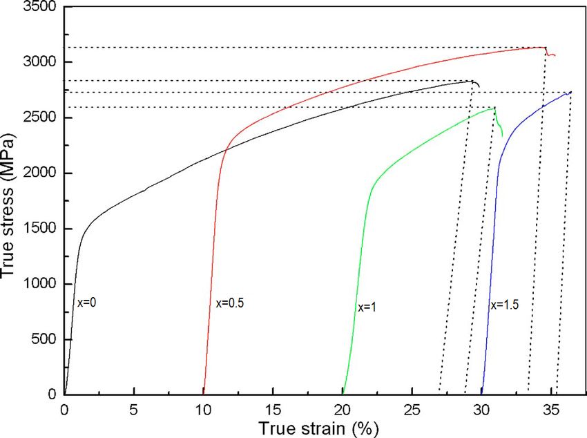
Heat-treatments such as multi-step-forging [45], annealing [46] and aging [47] at dif-
ferent temperatures can alter the properties. Forging increases tensile yield strength, ulti-
mate tensile strength and ductility to 1040 MPa, 1170 MPa, 1 % from 790 MPa, 790 MPa,
0.2 % for the arc-melted and cast AlCoCrCuFeNi and lowers the brittle to ductile tran-
sition temperature from 700 − 800 ◦ C to 600 − 700 ◦ C. Aging above 645◦ C gradually
changes the bcc structure to fcc, lowering the yield strength but increasing the plastic-
ity. As for annealing it increases the fcc phase as well, making it a possible control-tool
for the volume ratio between the fcc and bcc phases. Heat-treatments will also affect the
26You can also read