Hard carbons for sodium-ion batteries and beyond - IOPscience
←
→
Page content transcription
If your browser does not render page correctly, please read the page content below
Progress in Energy

TOPICAL REVIEW • OPEN ACCESS

Hard carbons for sodium-ion batteries and beyond
To cite this article: Fei Xie et al 2020 Prog. Energy 2 042002

View the article online for updates and enhancements.

                                This content was downloaded from IP address 46.4.80.155 on 17/12/2020 at 23:26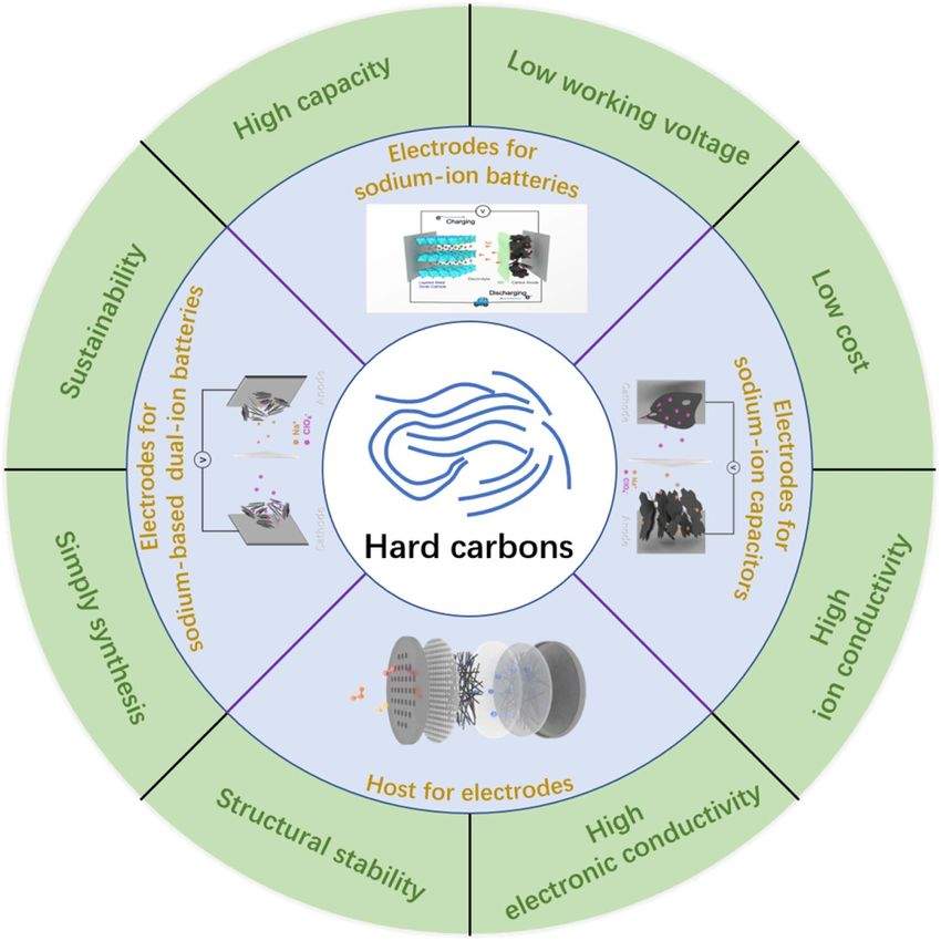
Prog. Energy 2 (2020) 042002 https://doi.org/10.1088/2516-1083/aba5f5
Progress in Energy
TOPICAL REVIEW
Hard carbons for sodium-ion batteries and beyond
OPEN ACCESS
Fei Xie1,2,3, Zhen Xu2, Zhenyu Guo2 and Maria-Magdalena Titirici2
RECEIVED 1
7 May 2020 Key Laboratory for Renewable Energy, Beijing Key Laboratory for New Energy Materials and Devices, Institute of Physics, Chinese
Academy of Sciences, Beijing, 100190, China
REVISED 2
28 June 2020 Department of Chemical Engineering, Imperial College London, London SW7 2AZ, United Kingdom
3
School of Physics and Astronomy, Queen Mary University of London, London E1 4NS, United Kingdom
ACCEPTED FOR PUBLICATION
14 July 2020 E-mail: m.titirici@imperial.ac.uk
PUBLISHED
Keywords: Sodium-ion batteries, hard carbons, anodes, energy storage
18 September 2020
Original content from
this work may be used Abstract
under the terms of the
Creative Commons Sodium-ion batteries (SIBs) are one of the most promising alternatives to lithium-ion batteries
Attribution 4.0 licence. (LIBs), due to the much more abundant resources of Na compared with Li in the world.
Any further distribution Developing SIB technology to satisfy the increased demand for energy storage is therefore a
of this work must
maintain attribution to significant task . However, one of the biggest bottlenecks is the design of high-performance and
the author(s) and the title
of the work, journal low-cost anode materials, since the graphite anode in commercial LIBs is not suitable for SIBs due
citation and DOI. to thermal dynamic issues. Hard carbon materials have been regarded as having the greatest
potential as anodes in commercial SIBs owing to their excellent cost-effectiveness, but their
relatively limited performance compared to the graphite in LIBs as well as the dimness of the
sodium storage mechanisms still need further investigation. In this review, we summarize the
progress of recent research into hard carbons for SIB applications, including the fundamentals of
SIBs, sodium storage mechanisms, structures and the electrochemical performances of different
types of hard carbons in SIBs and other types of sodium-based energy storage as well as the main
challenges in this field. We aim to provide a general insight into hard carbons and their
applications in SIBs, opening up future perspectives and possible research directions.
1. Introduction
CO2 emissions caused by burning fossil fuels have significantly increased to a rate which was, in 2017, twice
that of the rate of absorption back into the land and ocean [1]. Although researchers have already realized the
environmental detriments of using fossil fuels, including oil, coal, natural gas, etc., they continue to play a
key role in the current energy scenario. Therefore, the development of renewable and efficient new energy
generation, conversion and storage systems to reduce the use of fossil fuels is an urgent challenge today.
Lithium-ion batteries (LIBs), as a representative of secondary batteries, have made a great contribution to
energy storage since their first successful commercialization in the 1990s [2, 3]. With the increased usage of
electronic devices and electric vehicles (EVs), the demand for LIBs is also increased. In 2018, 11 583 research
papers were published in the field of lithium-based batteries. However, they are now facing bottlenecks,
especially considering that the average rate of increase of the energy density of commercial LIBs has been no
more than 3% in the last 25 years [4]. In addition, lithium resources are not widely distributed in the world
and are mainly located in South America, which tremendously restricts the future development of LIBs [5–7].
As a result, the alternative of using less expensive and more abundant metals for rechargeable batteries
has attracted research attention. In this respect, sodium, which is the element adjacent to lithium in the same
column of the periodic table, became the first option. Sodium is approximately 400 times more abundant
than lithium and is widely dispersed in the Earth’s crust and sea, so that the cost of sodium is only $150
ton−1 , which is much lower than the $5000 ton−1 of lithium [8, 9]. In addition, the use of low-cost metals
for the cathode in sodium-ion batteries (SIBs), such as Cu [10], could further reduce the total cost of SIBs
compared to the use of Co in LIBs [11].
One of the most significant challenges of SIB technology is designing low-cost and high-performance
electrode materials, especially anode materials, due to the unsuitability of graphite. Various cathode
© 2020 The Author(s). Published by IOP Publishing Ltd
Prog. Energy 2 (2020) 042002                                                                                F Xie et al

materials have also been widely investigated, most of which were inspired by LIBs [8], however, the anode
part is still the bottleneck as it dictates the C rates and also plays an important role in the solid electrolyte
interphase (SEI) formation and hence the overall Coulombic efficiency. Among all the materials which have
been tried as anodes for SIBs [8, 12], carbonaceous materials are regarded as the most promising because of
their relatively high structural stability and cost-effectiveness, especially when derived from low-cost
precursors like biowaste or plastic waste.
    In general, hard carbons cannot be graphitised even at very high carbonisation temperatures due to the
high oxygen and disordered structure of the precursors. They are disordered structures with
randomly-oriented graphitic domains, higher interlayer spacing and some remaining heteroatoms (mainly
oxygenated groups). They also have random closed pores in between the randomly-oriented graphitic
crystallites, whose size depends on the size of the crystallites (the higher the crystallites, the larger the pores).
Such a mix of crystalline and disordered structures provides more defects, more nanopores and larger
interlayer spacing, etc., and is therefore able to afford more sodium diffusion pathways and sodium storage
sites. It needs to be clarified that the oxygen content can form cross-linking regions or curved layers in the
hard carbon structures during the carbonization process, thus affecting the non-graphitisability of hard
carbons. A promising hard carbon precursor, therefore, should possess enough oxygen content to enable the
non-graphitisability of hard carbons. Although some other carbonaceous materials such as soft carbons
[13–15] or even graphite-based materials [16, 17], etc. could also be used as anodes for SIBs as long as they
are properly treated or combined with the hard carbons, hard carbon materials are definitely playing the key
role in this field. However, most of the reported hard carbon anode materials are still uncompetitive with
graphite in commercial LIBs, and the sodium storage mechanisms of hard carbons are still under debate due
to their different structures, which need further consideration.
    In this review, the fundamentals of SIBs and hard carbons are introduced. The current sodium storage
mechanism models and the electrochemical performance of different types of hard carbons in SIBs are
summarized. In addition, a brief introduction to the applications of hard carbons in other sodium-based
energy storage systems is also presented. At the end of this review, the main challenges are also addressed, in
which we aim to provide researchers with a general insight into hard carbons for SIBs and some possible
future directions. A summary of the characteristics and the applications of hard carbons in SIBs and other
sodium-based energy storage systems is shown in figure 1.

2. The fundamentals of sodium-ion batteries and hard carbons

2.1. Sodium-ion batteries
2.1.1. Sodium-ion batteries vs. lithium-ion batteries
LIBs, as representatives of rechargeable batteries, have achieved great success and development, being the
main portable power source in people’s lives over the past decades due to their high energy density. However,
with an increasing population and the development of electronic devices and EVs, the demand for LIBs has
significantly increased, which will lead to a deficiency of Li resources on the Earth and consequently
increasing prices, therefore, LIBs will gradually become unaffordable [18]. Consequently, finding alternative
sources to foster new battery technologies is a critical challenge. Due to the similarity of the physical and
chemical properties of sodium with lithium (as they are in the same group of elements in the periodic table),
SIBs or Na-ion batteries (NIBs) are regarded as one of the most promising candidates to partially replace
LIBs.
    The working principle of SIBs is same as LIBs, which is called the ‘rocking chair’ (figure 2): during
charge, the cathode desodiates and the Na+ ions ‘swim’ to the anode through the electrolyte and sodiate into
the anode, while electrons move from the cathode to the anode along the external circuit. During discharge,
the anode desodiates and Na+ ions return back to the cathode through the electrolyte, while electrons are
transported from the anode to the cathode along the external circuit, and the battery provides power to the
external circuit [19].
    The concept of sodium-ion batteries was first established at almost the same time as lithium-ion batteries
(1970s for LIBs and 1980s for SIBs) [19–21]. However, SIBs gradually faded out of sight soon after the
successful commercialization of LIBs in the 1990s [8], due to their lower specific capacity, lower energy
density and worse rate and cycling performance. The main and simplified reason why SIBs perform worse
than LIBs is that sodium is larger, heavier, and has a higher standard potential compared to lithium, which
causes SIBs to have a decreased capacity and a reduced range of redox potential. The radius and atomic
weight of sodium is 1.06 Å and 23 g mol−1 , respectively, while lithium is only 0.76 Å and 6.9 g mol−1 [9]
(table 1). This makes for larger volumetric changes when the Na concentration changes, which can end up
resulting in a strain build-up upon the insertion or extraction of Na+ ions and a reduce the cycling life. The
larger size of the Na+ ions will also affect the kinetic process and cause slower diffusion, which is the main

                                               2
Prog. Energy 2 (2020) 042002                                                                                              F Xie et al

            Figure 1. A summary of the characteristics and applications of hard carbons in sodium-based energy storage.

                               Figure 2. A scheme of the working principles of sodium-ion batteries.

                                                    3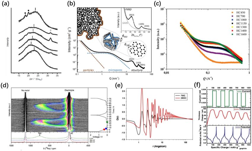
Prog. Energy 2 (2020) 042002                                                                          F Xie et al

                                        Table 1. A physical comparison of Li and Na.

Physical characteristic                                                      Li        Na

Cation radius (nm)                                                           0.076     0.106
Atomic weight (g mol−1 )                                                     6.9       23
Potential (V vs. SHE (standard hydrogen electrode))                          −3.04     −2.71
Ratio in Earth’s crust                                                       0.0065%   2.83%
Price of carbonates (                                                        ~5000     ~150
Theoretical capacity of metal (mAh g−1 )                                     3829      1165
Theoretical capacity of GICs in ester-based electrolytes (mAh g−1 )          372       35

reason for the poorer rate performance [22, 23]. In addition, graphite is usually selected as the anode
material in commercial LIBs due to its high cost-effectiveness, and it has a high theoretical specific capacity
of 372 mAh g−1 [24] due to the formation of graphite intercalation compounds (GICs). However, the bigger
Na+ ions do not intercalate into the graphite layers as do Li+ ions, due to thermal dynamic issues, which
further increases the challenges of finding suitable anode materials for commercial SIBs [25].
     Nevertheless, the assumption that Na+ ions are too large to intercalate into graphite layers (thereby
making graphite a poor material for storing sodium) is an oversimplification of a very complex picture. K+
ions with an even larger ion radius (1.38 Å) can happily intercalate into graphite [2, 26]. A graphite lattice
can accommodate Li+ ions up to a concentration of LiC6 with a very high theoretical specific capacity of
372 mAh g−1 . K+ ions can form K-GICs with a theoretical capacity of 279 mAh g−1 for KC8 [2]. However, in
the case of sodium, the concentration is only NaC186 [27] or NaC64 [28] with the extremely low theoretical
capacities of 12 and 35 mAh g−1 , respectively. Rb+ and Cs+ , which have even larger radii, were also
investigated for their ease of intercalation into graphite layers [2, 29]. Besides, the desolvation energy for
desolving the alkali metal ions from the electrolytes and transferring them to naked ions decreases in most
electrolytes from Li+ to K+ ions, meaning that Li+ ionintercalation should ‘theoretically’ be the most
difficult situation compared to Na+ and K+ ions when forming GICs [30, 31]. This inverted phenomenon
results in another controversial opinion that it is not the Na+ ions but actually the Li+ ions that suffer from
the special intercalation situation. The reason for the inferior intercalation behaviour of Na+ ions into
graphite was calculated to be that the attractive interaction between the Na+ ions and the graphite layers is
extremely weak, so that there are not enough energetic forces to motivate the intercalation, compared with
plating on the graphite surface [32]. Grande et al [33] also found, based on van der Waals density functional
theory (DFT) calculations, that the formation enthalpies are positive for NaC6 or NaC8 but negative for LiC6 ,
implying that the formation of Na-rich GICs requires a negative redox potential vs. Na+ /Na [34, 35].
     On the other hand, the intercalation potentials of Li+ ions (vs. Li+ /Li) and Na+ ions (vs. Na+ /Na) into
host materials are dependent on the materials’ structures. Generally, for common hosts, the standard
intercalation potentials are lower for sodium compared to lithium due to the higher potential of sodium than
lithium (see table 1) [31]. The same trend was also found in cathode materials, so that the operating voltage
of LIB and SIB full cells is dependent on the specific combination of both the positive and negative electrode
materials. According to the data reported in the literature [31, 36–40], a number of cathode materials have
lower sodiation/desodiation potentials (vs. Na+ /Na) for sodium than the lithiation/delithiation potentials
(vs. Li+ /Li) for lithium. The reduced values of the positive electrodes are greater than those of the negative
electrodes between Li and Na cells. Therefore, the cell voltage of SIBs is usually lower than LIBs, which means
the energy density of SIBs is not as high, compared with LIBs, in most cases [31].
     Based on the aforementioned shortcomings of SIBs, the development of SIB technology suffered from a
long period of silence before researchers started to realise the problem of Li resources and cost. However,
when compared to LIBs, the advantages of SIBs can be summarised as follows: (1) there are much more
abundant and widely-distributed resources of sodium than lithium. There is only 0.0065% of lithium in the
Earth’s crust which is mainly distributed in South America, while sodium makes up 2.83% of the Earth’s
crust and is plentiful all over the world especially in sea water, and therefore much cheaper [7, 41]; (2)
aluminium can be used as the current collector for electrodes in SIBs compared to copper in LIBs since
aluminium will form an alloy with lithium but not with sodium, which reduces the total cost and weight
[31]; (3) the desolvation energy of sodium ions in various organic solvents is around 30% smaller than for
lithium ions, which could decrease the charge transfer resistance and increase the electrode kinetics
[31, 42, 43]; (4) in addition to Ni, Co and Mn, which were found to be the only electrochemical active
transition metals among the layered oxide cathode materials, more choices are available for SIBs such as Cu,
Fe, Ti, V, Cr, etc., showing different electrochemical properties and providing more opportunities for the
development of SIBs [44]; (5) the use of hard carbon anodes and the differences in the thermal, chemical and
electrochemical properties enable more possibilities for electrolyte optimization, to obtain more favourable

                                                 4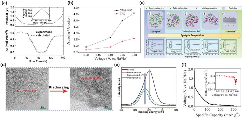
Prog. Energy 2 (2020) 042002                                                                              F Xie et al

sodium-based energy storage devices [45, 46]. In addition, similar technology and equipment to that used
for LIBs could be used for SIBs, which makes practical and industrial manufacturing easier. These benefits
give SIBs great potential for various markets such as low-speed electrical vehicles, home-use energy storage,
electronic devices and especially large-scale energy storage, etc., in the future.

2.1.2. Basic performance parameters for sodium-ion batteries
Generally, the main key parameters for evaluating the performance of SIBanodes include the specific capacity,
energy density (gravimetric and volumetric), rate capability, cycling stability, and the initial Coulombic
efficiency (ICE), which strongly depends on the electrode materials, electrolytes, and even the additives.
     The theoretical specific capacity Qt of an electrode material can be determined by Faraday’s law [47]:
                                               (       )   nF
                                             Qt mAh g−1 =                                                       (1)
                                                          3.6M
where n is the number of transferred electrons, F is the Faraday constant (96 485 C mol−1 ) and M is the
molecular mass of the active material. In a practical situation with a galvanostatic charge/discharge status,
the specific capacity is calculated by [48]:
                                              (       )   I∆t
                                             Q mAh g−1 =                                                        (2)
                                                         3.6m
where I (mA) is the charge/discharge current, ∆t (h) is the charge/discharge duration and m (g) is the mass
of the active material. Taking carbonaceous materials as an example, the capacity is affected by the
morphology, pore structures, ordering structures, and defects, etc., which are discussed in the next sections.
    The gravimetric energy density of a full SIB cell is the integration of the voltage and the specific capacity.
The theoretical energy density is calculated based on the following equation [49]: the Gibbs free energy of a
standard chemical reaction is the sum of the formulation energy of the reactants and products:
                                        ∑∆ r        ∑∆f          ∑∆ f
                                               G=         Gp −          Gr .                                    (3)

    The maximum electrical work of the reaction equals ∆r G:

                                                  ∆r G = −nFE                                                   (4)

where n is the number of transferred electrons of one mole of reactant and E is the thermodynamic
equilibrium voltage. Therefore, the theoretical gravimetric energy density can be calculated as:
                                                        ∆r G
                                                   εM = ∑ M                                                     (5)

      ∑
where M is the sum of the mole weight of all the reactants. In practical situations, the energy density is
determined as [48]:
                                                      I
                                               ε=        ∫ U (t) dt                                             (6)
                                                    3.6m
where U represents the voltage window (the volumetric energy density could be calculated in the same way
but replacing the mass with the volume). Thus, in addition to increasing the specific capacity of the electrode
materials, another way to obtain a high energy density is to elevate the working voltage. That requires a
higher voltage of the cathode materials and a lower voltage of the anode materials. The average working
voltage of a SIB is the quotient of the integrated area of the charge/discharge profile (the specific energy
density) and the total specific capacity. In practice, it usually refers to the voltage at the half of the specific
capacity or at the half-integrated area of the galvanostatic charge/discharge profiles. Meanwhile, since a high
operating voltage may be beyond the electrochemically stable window of the electrolytes and binders, it is
also important to expand the thermodynamically stable potential window of the electrolytes by using proper
recipes or adding additives, as well as selecting appropriate binders [50]. Furthermore, it is worth noting that
in lab-based experiments, it is usual to calculate the energy density of a full cell based only on the mass of the
active materials of both cathode and anode. However, in practical or industrial batteries, the energy density
calculation should involve the masses of all the other materials including current collectors, binders,
additives, separators and cases, etc. [51]. As a result, controlling the mass of those non-active and packing
materials is also very important to improve the energy density.
    The rate capability represents the reversible capacity of an electrode material at different current densities.
Capacities will typically decrease at higher current rates because the electronic current density is much larger

                                              5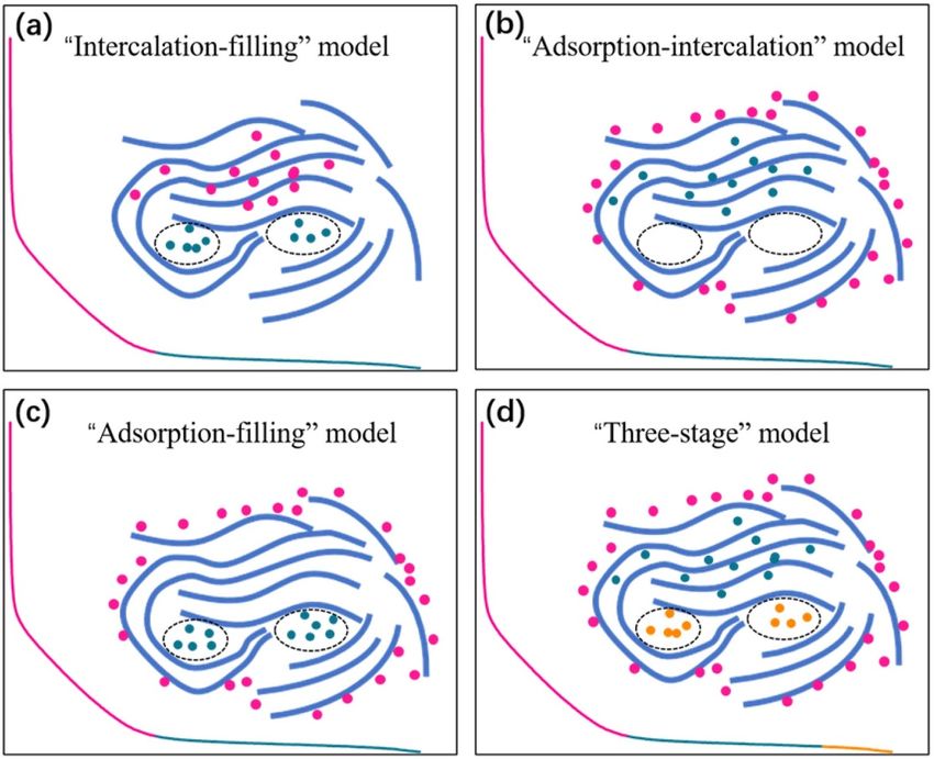
Prog. Energy 2 (2020) 042002                                                                               F Xie et al

than the ionic current density of the electrolyte and electrodes (and the rate of ion transfer across the
electrolyte/electrode interface) [52], meaning that stronger polarisation takes place at high current rates.
     The cycling performance relates to the stability of the battery during the long-term charge/discharge
process. The lifespan of a battery is defined to be the cycle number at which the capacity retention drops to
80% of its initial capacity [53]. Generally, cycling stability is mainly determined by the interface between the
electrode and the electrolyte and by the structural stability of the electrode materials. The
electrode/electrolyte interphase is affected by the formation of SEI, which is a passivation layer on the surface
of the electrode when the Fermi level of the anode is above the lowest unoccupied molecular orbital (LUMO)
of the electrolyte (or the Fermi level of the cathode is lower than the highest occupied molecular orbital
(HOMO) of the electrolyte) so that the electrolyte is decomposed to form inorganic insoluble compounds
[52, 54]. A stable SEI is beneficial to eliminate further decomposition of the electrolyte during cycling, which
ensures the reversible insertion/desertion of Na+ ions. The mechanical properties of the SEI are also
important in protecting the electrode materials against volume expansion and maintaining the adsorption
capacity on the surface [54]. For some anode materials such as alloys, the huge volume expansion during
charge/discharge significantly limits the cycling stability, and some strategies including surface coating, and
heteroatom doping, etc., would be useful to overcome this phenomenon and improve the cycling
performance [19, 55]. Good interface and structural stability is required to ensure a high enough Coulombic
efficiency (CE) during the charge/discharge process, and it is found that a high CE of 99.96% is needed for
commercial batteries when cycling to over 500 cycles [4].
     ICE is the quotient of the initial discharge capacity divided by the initial charge capacity (for the anode
half-cell it is the quotient of the initial charge capacity divided by the initial discharge capacity) which is also
a significant parameter for SIB technology but gets less attention compared with other parameters. Since the
cathode material usually serves as the Na source in a full battery, it should provide Na+ ions for reversible
cycling as well as the consumption of Na+ ions for SEI formation at the first cycle [56]. Therefore, not only
does ICE reveal the SEI formation and irreversibility of sodiation/desodiation reactions at the first cycle, but
also it affects the energy density of a full battery, as more cathode materials have to be used to cover the initial
irreversible Na+ ion consumption which results in an increased weight of the battery and a decreased energy
density. Some factors were found to influence the ICE including irreversible decomposition of the electrolyte,
an irreversible reaction during sodiation/desodiation, and the defects and porosity, etc. As a result, optimising
the electrolytes and tuning the nanostructures and surface area would be helpful to improve the ICE [56].

2.2. Hard carbons
The differences between hard carbons, soft carbons and graphite have been intensively reviewed in the
literature. Typically, in addition to the mechanical properties (as suggested, hard carbons are ‘harder’
compared with the other two forms of carbon), a more specific definition is that these carbon materials
cannot be graphitised even at a very high temperature (over 3000 ◦ C), while the soft carbons correspond to
the ‘graphitizable’ carbonaceous materials [57, 58].
     On the other hand, some terms or definitions are usually misused in the literature, such as ‘amorphous
carbons’. It has been reported that ‘amorphous carbons’ only describes the carbonaceous materials
containing localized π-electrons (i.e. diamond-like carbons) [58]. In other words, amorphous carbons
belong to the hard carbons, as they cannot be graphitised, but hard carbons are not only the amorphous
carbons. For energy storage applications, carbonaceous materials are usually treated at between 600 ◦ C and
2000 ◦ C; within this range both ‘hard carbons’ and ‘soft carbons’ have disordered or non-graphitic
structures, but ‘soft carbons’ will be relatively more ordered compared to the ‘hard carbons’ when carbonized
at the same temperature. When the pyrolysis temperature increases to a very high level, the ‘hard carbons’ are
still disordered, while the ‘soft carbons’ become graphite or pseudo-graphite.
     As electrode materials, although hard carbons do not have as high a specific capacity as chalcogen-based
materials and alloys, their capacity can approach the commercial graphite anodes of LIBs, and their lower
working voltage can be a good point for improving the energy density [9]. In addition, their limited volume
change (unlike alloy and conversion anodes) and structural stability ensure that carbonaceous anode
materials have a better cycling performance [59]. Hard carbons have more disordered structures, a higher
concentration of defects, a higher content of heteroatoms and a larger distance between the graphitic layers
as well as more closed pore structures compared with soft carbons, which facilitate more storage sites and
diffusion pathways for Na+ ions, and are regarded as the most promising candidates for SIB anode materials.
Furthermore, the low cost, sustainability, and simplicity of manufacture also make hard carbon materials the
most promising candidates for the practical commercialisation of SIBs [58, 60, 61].

                                               6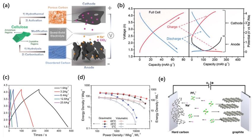
Prog. Energy 2 (2020) 042002                                                                                                    F Xie et al

   Figure 3. A schematic of the sodium storage models: (a) the ‘intercalation-filling’ model; (b) the ‘adsorption-intercalation’ model;
   (c) the ‘adsorption-filling’ model and (d) the ‘three-stage’ model.

3. Sodium storage mechanisms and interfaces of hard carbons

3.1. Sodium storage models of hard carbons
While extraordinary research achievements have been made in the field of hard carbon anode materials for
SIBs, owing to contributions from many research groups, the sodium storage mechanisms in carbon anode
materials are still controversial. This is not surprising, given the fact that hard carbons are ‘ill-defined’
materials with different crystallite sizes, pore structures, heteroatoms, etc. People still debate the sodium
storage behaviours at carbon electrodes within the sloping or plateau regions of a typical galvanostatic
discharge/charge profile, which can be summarised in three categories: (1) Na+ ions adsorb at the defect sites
on the surface; (2) Na+ ions intercalate into graphitic layers; (3) Na+ ions fill the nanopores. Based on these
three kinds of sodium storage behaviour, the sodium storage mechanism can be categorised into four
models: (1) the ‘intercalation-filling’ model: Na+ ions intercalate into graphitic layers in the sloping region,
and insert into the nanopores between randomly stacked layers at the plateau region [27, 62]; (2) the
adsorption-intercalation model: Na+ ions adsorb at the surface or defect sites of the carbon electrodes within
the sloping region, while they intercalate into the graphitic layers within the plateau region [63, 64]; (3) the
adsorption-filling model: in the sloping region, Na+ ions adsorb at the defect sites, while filling the
nanopores in the plateau region [65, 66]; and (4) the ‘three-stage’ model: defect adsorption of Na+ in the
sloping region, but in the plateau region, the Na+ ions first intercalate into the graphitic layers and eventually
fill in the nanopores [67]. A schematic of the four types of sodium storage models is shown in figure 3.
      The first investigation of sodium storage mechanisms was reported by Stevens and Dahn in 2000 [27].
They thought that the sodium storage mechanism is similar to that of LIBs and proposed the
‘intercalation-filling’ model. The in situ wide-angle x-ray scattering (WAXS) showed that the Na+ ions
intercalate into the graphitic layers within the sloping region based on the (002) peak position shift for soft
carbons. Although the (002) peak for hard carbons does not show such an obvious shift, due to the existence
of single, double or triple stack layers of hard carbons, the authors think that similar intercalation can still
occur for hard carbons. Based on in situ SAXS measurements, the electron density remains unchanged in the
high-potential region while decreasing at lower potentials [68], suggesting nanopore filling in the plateau
region (figure 4(a)).
      In 2012, Cao and Liu et al [63] claimed another adsorption-insertion mechanism, namely that the
sloping region is attributed to adsorption of the sodium on the surface of small graphitic clusters, while the
plateau region is due to the sodium insertion into the graphitic interlayers. Based on the theoretical

                                                        7
Prog. Energy 2 (2020) 042002                                                                                               F Xie et al

   Figure 4. (a) The calculated electron-density contrast obtained from in situ small-angle x-ray scattering (SAXS) scans during
   discharge and charge. Reproduced from [68] © 2000 The Electrochemical Society. All rights reserved. (b) The interlayer spacing
   changes at different discharge voltages. Reprinted with permission from [64]. Copyright (2013) American Chemical Society. (c) A
   schematic of the extended ‘adsorption-intercalation’ model of hard carbons at different stages. [69] John Wiley & Sons. © 2019
   WILEY-VCH Verlag GmbH & Co. KGaA, Weinheim. (d) Ex situ transmission electron microscopy (TEM) images and (e) ex situ
   x-ray photoelectron spectroscopy (XPS) Na1s spectra of hard carbon from pristine to 0 V (vs. Na+ /Na). [66] John Wiley & Sons.
   © 2016 WILEY-VCH Verlag GmbH & Co. KGaA, Weinheim. (f) A galvanostatic intermittent titration technique (GITT) profile
   and the corresponding Na+ ion diffusion coefficients during discharge. Reprinted with permission from [67]. Copyright (2015)
   American Chemical Society.

simulation, the authors concluded that the minimum interlayer distance for Na+ ionintercalation is 0.37 nm.
This model was further supported by Mitlin and Li et al in 2013 [64]. They used carbonised peat moss with
(CPM-A) and without activation (CPM) as well as commercial activated carbons (CACs) to investigate
sodium storage performance and the sodium storage mechanism. The sloping capacity increased with
increasing carbonisation temperature. It was found that CACs with a high surface area and many micro- and
mesopores do not show any plateau, suggesting that the low-potential plateau should not be attributed to
pore filling. According to the XRD spectra of CPM-1400 and CAC at different discharge voltages, the much
more obvious d-spacing changes in the plateau than in the slope indicates that the plateau region is due to the
insertion of Na+ ions into the carbon layers (figure 4(b)). Very recently, Xu and co-workers [69] published
their research on the sodium storage mechanism of hard carbons and proposed an ‘extended
adsorption-intercalation model’ by using ginkgo leaf (GL)-derived carbons carbonized at various
temperatures (GL-T) and correlated the structures with the sodium storage performance (figure 4(c)). High
resolution transmission electron microscopy (HRTEM) images show three carbon domains: highly
disordered domains, pseudo-graphite domains and graphite-like domains, depending on the carbonisation
temperature. Based on the ‘volcano-shape’ tendency of both sloping and plateau capacities along with the
temperature series, the authors correlated the capacities with the structures and proposed a model that can
be summarised as follows: (1) the very large interlayer spacing (>0.4 nm) from the highly disordered carbons
would be regarded as ‘defects’ and Na+ could be freely accessed, the same as the defect-adsorption behaviour,
which leads to only the sloping region; (2) the smaller interlayer spacing (0.36–0.4 nm) is accessible for
intercalation and would cause the plateau region; (3) the graphite-like carbons with a very small interlayer
spacing (
Prog. Energy 2 (2020) 042002                                                                           F Xie et al

Na+ ions. Ex situ TEM was used to investigate the microstructures of pristine carbon and the same sample
discharged to 0 V (vs. Na+ /Na), where the disordered structures did not change and the interlayer spacings
were both around 0.404 nm, indicating that no intercalation happened (figure 4(d)). Figure 4(e) shows the
ex situ XPS Na 1s spectrum, where the peaks of the carbon samples are approaching the metallic sodium
when discharged from 0.12 to 0 V (vs. Na+ /Na), which may be due to the lower binding energy of pore
surface adsorption. According to the above results, the authors summarized that the Na+ ions are adsorbed
at the defect sites in the sloping region, and fill in the nanovoids in the plateau region, which is consistent
with some other reports [70, 71].
    The last sodium storage model is the ‘three-stage’ mode proposed by Ji et al [67] The GITT and the
corresponding calculated diffusivity (figure 4(f)) indicate that the Na+ ion diffusion in the sloping region is
much faster than in the plateau region, suggesting that the sodiation in the sloping region happens at the
more easily accessible surfaces and edges. By correlating the defect concentration with the sloping capacity
plus the ex situ XRD results showing the position shift of the (002) peaks in the plateau region, an
‘adsorption-intercalation’ mechanism seems best suited to describe this situation, which is also consistent
with the GITT result that the decrease of the diffusion coefficient in the plateau results from the Na+ ions
overcoming the repulsive charge from the previously bound defect sites and inserting into the carbon layers.
However, the Na+ ions’ diffusivity increases again at the end, suggesting that the plateau can not be attributed
to only one intercalation mechanism. Therefore, the authors claimed that there is a minor adsorption of Na+
ions on the pore surfaces at the end of the sodiation process, denoting a ‘three-stage’ model instead.
    Although several controversial sodium storage models have been reported so far, they could still guide
the design of optimised carbon materials for sodium-ion battery anodes. Making hard carbon materials with
more defects, a larger interlayer spacing and more closed pores would be mostly acceptable for achieving
high sodium storage performance. However, understanding the exact sodium storage mechanisms is still
significant from a fundamental point of view. In our opinion, there may not be only one correct sodium
storage model for hard carbon anodes; sodium storage mechanisms could be varied, based on different
microstructures. Therefore, generalising the sodium storage behaviours with different microstructures of
hard carbons would very important for future research.

3.2. Advanced characterisations for sodium storage mechanism investigations
So as to better understand the sodium storage mechanisms of hard carbons, clear investigations of the
structures of hard carbons and the correlation between the structures and electrochemical properties are
necessary, which therefore requiresome advanced characterisation techniques. One of the most commonly
used methods is in situ or ex situ XRD, which could easily study the intercalation behaviour of Na+ ions
within the graphitic layers. Komaba et al [72] have studied the sodiation and desodiation processes of hard
carbon electrodes by ex situ XRD and found that the (002) peaks shifted to lower angles and the intensities
decreased during sodiation, and could return back to the original position after full oxidation (figure 5(a)),
indicating the reversible intercalation/deintercalation of Na+ ions within the graphene layers. On the other
hand, in some studies, the (002) peak shifts in the ex situ or in situ XRD only occured at the plateau regions
[64, 67], or did not occur at all during the sodiation process [65], based on which, some other sodium storage
models have been announced, as illustrated in the last section. However, due to the disordered structures of
hard carbons, the (002) peaks are usually weak and broad, and the sample manufacture when using ex situ
operations may also influence the accuracy of the results [11]. Therefore, combining the XRD data with
other data would be necessary to generally consider the sodium storage mechanism, which needs further
studies. Another advanced x-ray analysis method for sodium storage mechanisms is the SAXS, which is able
to obtain the pore information. The SAXS patterns of hard carbons usually contain one slope in the low Q
region, corresponding to the particles or large pores at the surface, while a shoulder at the higher values of Q
is attributed to the nanopores among the turbostratic nanodomains (figure 5(b)). As shown in figure 5(c), it
is reported that the slopes of the hard carbons carbonised at various temperatures are quite similar, implying
that the surface large pores of hard carbons are almost unchanged with varying pyrolysis temperatures, while
the intensities of the shoulder increase with elevated temperatures, indicating larger pore sizes. The pore
number was also investigated and found to decrease with increasing temperatures. In situ or ex situ SAXS was
also used to observe the pore changes during sodiation [27, 68]; as demonstrated in the above section, the
electron density of the nanopores decreases within the plateau regions (figure 4(a)), suggesting the use of the
pore filling mechanism, which was further supported by the recent publication of [11] and [77].
     Gotoh and co-workers [78] have further confirmed by in situ and ex situ7 Li solid-state nuclear magnetic
resonance (NMR) for the case of LIBs that Li metal clustering occurs in the nanopores. In 2016, Grey et al
[74] used 23 Na solid-state NMR to investigate hard carbon electrodes in SIBs. It was found that during the
low-voltage plateau, the 23 Na NMR peak shifted from zero ppm which is typical for Na+ ions to around 760
ppm near the metallic Na, suggesting that Na pooling occurred and Na clusters were formed. Within the

                                             9
Prog. Energy 2 (2020) 042002 F Xie et al
Figure 5. (a) Ex situ XRD patterns of hard carbon electrodes, from top to bottom: pristine, 0.4 V, 0.2 V, 0.1 V, 0 V during sodiation
and 2 V upon desodiation. [72] John Wiley & Sons. Copyright © 2011 WILEY-VCH Verlag GmbH & Co. KGaA, Weinheim. (b) A
schematic illustration of the SAXS patterns with the corresponding nanostructures for each part. Reprinted from [58], Copyright
(2019), with permission from Elsevier. (c) The SAXS patterns of hard carbons carbonised at different temperatures. Reprinted
from [73] © 2016 Science Press and Dalian Institute of Chemical Physics, Chinese Academy of Sciences. Published by Elsevier B.V.
and Science Press. All rights reserved. (d) Operando 23 Na NMR spectra for a hard carbon electrode in a half cell. Reproduced
from [74]. CC BY 3.0. (e) The neutron PDF spectra of hard carbons carbonised at different temperatures. Reprinted from [75],
Copyright (2014), with permission from Elsevier. (f) The in situ electrochemical dilatometry spectra of graphite for the first five
cycles. [76] John Wiley & Sons. © 2018 WILEY-VCH Verlag GmbH & Co. KGaA, Weinheim.
high-voltage sloping region, the 23 Na NMR signal remained at the ionic state, indicating that the Na+ ions
formed in this region, which could be due to defects. Another advanced characterisation technique usually
applied to the investigation of defects in hard carbon materials is the neutron pair distribution function
(PDF). The peak positions in the spectra correspond to the real-space distances between arbitrarily selected
pairs of atoms, and the peak integrals suggest the coordination numbers of the atom pairs near a specific
distance [79]. Therefore, as shown in figure 5(e), hard carbon carbonised at 2800 ◦ C shows a much higher
peak amplitude compared to hard carbon carbonised at 700 ◦ C, indicating the fact that hard carbon
materials show more ordered structures and fewer local defects when treated at higher temperatures. Ji et al
[67, 79, 80] reported on several studies of the correlation between the neutron PDF results and the
electrochemical properties of hard carbons to investigate sodium storage behaviour regarding defects and
claimed that the defect adsorption of Na+ ions may be the main reason for the sloping capacity.
Adelhem et al [76] reported on in situ electrochemical dilatometry (ECD) as an effective technique to
study the sodium storage behaviours of graphite as a cointercalation electrode. Figure 5(f) shows the ECD
results for the graphite electrode. It was found that the thickness of the electrode nearly doubled (from 50 to
95 µm) after the first sodiation, suggesting larger structure rearrangement and particle loosening during the
first cycle. During the subsequent cycles, the thickness showed a periodic ‘breathing’ of about 35–50 µm in
each cycle, which could be attributed to the reversible intercalation/deintercalation process. Although this
result was for a graphite electrode, the ECD technique can be applied to hard carbon electrodes as well for
investigation of the sodium storage mechanism.
Some other advanced characterisation techniques such as x-ray PDF and muon spin, as well as DFT
calculations, etc., [81–83] have also been reported as having been used to investigate the structures and
sodium storage mechanisms of hard carbon materials. The utilization of these advanced characterisation
techniques for SIB applications would push forward not only the understanding of SIBs but also the
techniques themselves. Meanwhile, there are also some limitations when using these methods. For example,
ex situ experiments would require the disassembly of cells, which makes for more complexity and may cause
sample contamination due to air sensitivity. The neutron and muon analysis methods need a huge number of
samples for the measurements, which increases the difficulty of operation. Therefore, the choice of proper
10Prog. Energy 2 (2020) 042002 F Xie et al
techniques and careful combination with other analyses is very important for sodium storage mechanism
studies in practical situations.
3.3. The solid electrolyte interphase on hard carbon anodes
During the first cycle of the charge and discharge process, a passivation layer called a solid-electrolyte
interphase (SEI) will form on the surface of hard carbon anodes if the Fermi level of the anode material is
higher than the lowest unoccupied molecular orbital (LUMO) of the electrolyte [52]. Therefore, the
electrolyte is automatically decomposed to form a SEI consisting of both inorganic and organic insoluble
compounds so that the voltage window of the system becomes broad enough to allow the redox reaction of
energy storage to happen. The SEI layers protect hard carbon anodes from direct contact with the electrolyte
but still allow ions to move through the SEI layers, which means the SEI layers are a kind of pure ionic
conductor [72].
The formation of an SEI is firstly related to the type of electrolyte used. For ester-based electrolytes, the
degraded inorganic and organic components often geometrically form a random mixture, while for
ether-based electrolytes, the degraded inorganic particles are intended to be incorporated into a continuous
phase consisting of organic components [84]. The use of different types of electrolytes and the different
electrode/electrolyte interfaces will affect the sodium storage performance, especially the ICE. It has been
reported that the use of ether-based electrolytes is helpful for increasing the ICE, as the LUMO of ether-based
electrolytes is calculated to be higher than that of ester-based electrolytes [54]. Even for some carbon anode
materials with very high surface areas, the use of ether-based electrolytes can still lead to high ICE [85, 86],
implying a great potential. In addition to the electrolytes used, the formation of an SEI is closely related to
the properties of hard carbon anodes. Defects and a porous structure can increase the amount of SEI formed
during the first cycle, thus decreasing the ICE of hard carbon anodes. For example, although porous hard
carbon anodes could provide a high reversible capacity, the ultra-low ICE of those hard carbon anodes
requires an excess amount of Na ions from the cathodes to irreversibly form an SEI in the first cycles, which
results in a non-negligible waste of the expensive cathode materials. Furthermore, the slope-dominated
charge-discharge features will also decrease the working voltages and energy density of full cells, although
they could improve the rate performance at high current density. The structures of hard carbons need to be
tuned to achieve a balance between several parameters including the ICE, energy and power density. More
detailed examples will be discussed in the following sections.
There are several methods that can be employed to characterise the SEI on hard carbon anodes. First of
all, the most commonly used two techniques are transmission electron microscopy (TEM) and x-ray
photoelectron spectroscopy (XPS). TEM can help characterize the morphology of SEI formation, but the
difficulty of sample preparation and the limitation of the resolution of TEM greatly hinder the
characterization accuracy of this technique. With the development of TEM techniques, operando TEM
characterization and high-resolution cryo-EM appeared, thus significantly improving what we know about
the SEI. Cui and co-workers [87] successfully employed cryo-EM to achieve high-resolution images of SEI in
different kinds of electrolytes, which opened up the way for future work. XPS can help to partially
distinguish the components of SEI. Meng and co-workers [88] applied XPS to characterise the different
components of SEI in ester- and ether-based electrolytes, where ether-based electrolytes can provide more
organic components in the SEI and thus lead to a good flexibility of the SEI in ether electrolytes. Secondly,
modelling methods are also widely employed to help analyse the formation of an SEI on hard carbon anodes
[89]. According to the calculation of the energy levels of different electrolyte molecules and active materials,
we can determine their effect on the formation of an SEI. Based on molecular dynamic modelling, the effect
of electrolyte concentration on the formation of an SEI can also be analysed. Moreover, other methods like
23
Na NMR can also help in the characterization of SEI formation.
However, the detailed SEI formation behaviours are quite complex because they are obviously affected by
numerous factors, from the properties of the electrode materials to the properties of the electrolytes. More
effort is needed to figure out the mechanism of how the SEI is formed during the initial cycles and how the
structures of hard carbons affect the formation of an SEI, thus figuring out a suitable solution to achieve a
high ICE at the first cycle and a stable SEI during subsequent cycles.
4. Hard carbons for sodium-ion batteries and other sodium-based energy storage
4.1. Biomass-derived hard carbons
Biomass is a class of abundant, sustainable, low-cost and economical precursors, usually containing plenty of
C content with some O, H and even some other heteroatoms such as N, S, P, etc. Biomass is a great choice as
a renewable and sustainable precursor for producing low-cost and high-performance hard carbon anode
materials for SIBs. The conversion of biomass into hard carbons is based on simple strategies such as direct
11Prog. Energy 2 (2020) 042002 F Xie et al
Figure 6. (a) An SEM image and (b) the rate capability (from 0.1 to 10 A g−1 ) of a hollow carbon sphere. [90] John Wiley & Sons.
Copyright © 2012 WILEY-VCH Verlag GmbH & Co. KGaA, Weinheim. (c) The initial discharge/charge curves of hard carbons
carbonized at different ramp rates. [91] John Wiley & Sons. © 2018 WILEY-VCH Verlag GmbH & Co. KGaA, Weinheim. (d)–(e)
Galvanostatic discharge/charge profiles of various biomass precursors and cellulose pre-treated at different temperatures,
respectively. (f) A schematic of the microstructural changes of cellulose due to preheating treatment. Reproduced from [92] with
permission of The Royal Society of Chemistry. (g) A schematic diagram of the synthesis of cellulose-derived carbon dots (CCDs)
and cellulose-derived HTC carbon spheres (CHTCs) from the supernatant and deposit of a hydrothermal carbonisation (HTC)
process. (h)–(i) The initial discharge/charge profiles of CCD and CHTC carbonized at 1000 and 1300 ◦ C, respectively.
Reproduced from [77] with permission of The Royal Society of Chemistry.
carbonisation [11, 66, 93], hydrothermal carbonisation (HTC) [91, 94, 95], and physical or chemical
activation [48, 96], etc.
The first investigation of hard carbon as an anode in SIBs was proposed by Dahn et al [62], using glucose
as a precursor. A classical work about hard carbon anode materials with an excellent rate capability achieved
by an synthetic hollow nanosphere structure was proposed by Maier and White et al [90]. The hollow carbon
nanospheres were made from mixed poly(styrene) and D-glucose dispersion by HTC at 180 ◦ C for 20 h.
After washing, the carbon products were carbonised at 1000 ◦ C to remove the polymer template and hollow
carbon nanospheres were obtained; their morphology is shown in figure 6(a). The hollow carbon
nanospheres were able to deliver a specific capacity of 223 mAh g−1 at 50 mA g−1 with only a sloping region.
However, due to a high surface area of 410 m2 g−1 , the hollow carbon nanospheres had a very low ICE of
41.5%. More importantly, this hard carbon material showed a very superior rate capability that offered 168,
142, 120, 100, 75 and 50 mAh g−1 at current densities of 0.2, 0.5, 1.2, 5 and 10 A g−1 , respectively
(figure 6(b)). The authors explained and concluded the reasons for the good rate performance were as
follows: (1) the well-connected hollow structures were beneficial for electron transport; (2) a large number of
active sites and a good charge transfer reaction were obtained due to the large electrode/electrolyte contact
area; (3) the bigger interlayer space was good for sodium storage; (4) the thin shell thickness led to a short
Na+ ion diffusion distance. Subsequently, lots of studies about hollow carbon nanospherical materials and
their applications for energy storage have been reported [97–100]. Lately, Wan, Cao and Hu et al [71]
successfully synthesised multi-shelled hollow carbon nanospheres (MS-HCNs) as high-performance
sodium-ion battery anodes. The synthesis strategies were described in the previous report [101]. It was
found that with an increased number of shells, the specific capacity would also increase, whereby 4S-HCNs
were able to deliver the highest specific capacity and rate capabilities of 360 and 200 mAh g−1 at 30 and
600 mA g−1 , respectively.
12Prog. Energy 2 (2020) 042002 F Xie et al
A series of low-defect and low-porosity hard carbon (HC) materials derived from sucrose have been
investigated, correlating carbon structures with electrochemical performance at different heating rates (five,
two, one and 0.5 ◦ C min−1 , denoted as HC-5, HC-2, HC-1 and HC-0.5, respectively). Lower heating rates
proved to give rise to relatively more ordered structures and smaller specific surface areas, resulting in specific
capacities of 338, 344, 350, and 361 mAh g−1 with an ICE of 78.9%, 81.3%, 85.2% and 86.1%, respectively
(figure 6(c)), indicating that the lowest heating rate would also lead to the highest specific capacity and initial
Coulombic efficiency. The authors concluded that the lowest defect concentration and nondetectable
porosity were also the reasons that the HC-0.5 delivers the highest specific capacity and ICE [91]. Komaba
and co-workers [92] have investigated hard carbon anode materials made from various biomass precursors,
including glucose, sucrose, maltose, cellulose, glycogen and amylopectin. All the precursors were first
pre-heated at 180 ◦ C for 12 h in air and then carbonised to 1300 ◦ C in Ar, while cellulose was also carbonised
to 1300 ◦ C with different pre-heating temperatures. The corresponding galvanostatic discharge/charge
curves at 25 mA g−1 are shown in figures 6(d)–(e). It is obvious that the cellulose-derived hard carbons
delivered the best performance, and a pre-heating temperature of 275 ◦ C further enhanced the specific
capacity. It was concluded that a high-temperature pre-heating treatment can lead to dehydration and a
highly cross-linked structure and interrupted graphitisation during the high-temperature carbonization
process, which results in larger pores and interlayer spacing and provides more sodium storage sites.
HTC is a powerful technology for converting biomass precursors into spherical carbon materials which
can be applied for energy storage upon further carbonisation [6, 95, 102]. An HTC pre-treatment plays an
important role for the production of biomass-derived hard carbon anode materials in SIBs, especially for
sucrose, which would suffer a foaming process under direct carbonisation [67, 103], and HTC-treated hard
carbons do show great sodium storage performance according to the literature [61, 104, 105]. Very recently,
Titirici et al [77] have reported that not only can the conventional carbon spheres from the precipitate of the
HTC process be used as SIB anodes, but the supernatant from the HTC autoclave containing carbon dots
also exhibits excellent sodium storage performance upon drying and carbonization (figure 6(g)). In
particular, cellulose-derived carbon dots (CCDs) from the liquid phase of HTC can deliver much higher
specific capacity and an ICE of 266 mAh g−1 and 82% at 0.1 C, respectively, compared with the
cellulose-derived HTC carbon spheres (CHTCs) at 1000 ◦ C figure 6(h). CCDs carbonized at 1300 ◦ C show a
comparable reversible capacity of over 300 mAh g−1 but still an ultrahigh ICE of 91% (see figure 6(i)). The
same trend for a significantly enhanced ICE also exists in the case of glucose, suggesting the universality of
this discovery, which provides a new aspect of the design of hard carbon anode materials for SIBs.
There is another class of hard carbon materials, porous carbons, made through templating strategies such
as chemical activation [48, 106], physical activation [96] and salt-templating [107], etc. Many
biomass-derived porous carbons have been used as anodes in SIBs, which present excellent performance
[108–114]. However, a serious problem with such porous materials is the ultralow ICE caused by the
electrolyte decomposition and SEI formation due to the very high specific surface area, which significantly
limits their future potential for SIBs. Further consideration of improving the ICE of porous carbons is
necessary and important.
In addition to the aforementioned biomass precursors, banana peels [115], peat moss [64], rice husks
[93], cotton [66], glucose [116], protein [110], and cellulose nanocrystals [117], etc. have all been utilised as
anode materials for SIBs showing good electrochemical properties. A high-temperature-induced hard carbon
derived from charcoal (made from wood) was reported to deliver an ultrahigh specific capacity of
~400 mAh g−1 [118], suggesting the great potential of biomass to facilitate the development of anodes in
SIBs. Nevertheless, on the other hand, biomass from Nature usually contains some impurities that need to be
removed before it can be applied for SIB anodes. The most-reported biomass-derived hard carbon anodes
can deliver reversible capacities of up to 300 mAh g−1 with an ICE below 85%, which still cannot compete
with the graphite anode in commercial LIBs. Although biomass has its sustainability and abundance, the
general cost is still higher than that of graphite and soft carbons [119]. Therefore, a long journey is still
required for biomass-derived hard carbons to be used in commercial high-performance SIBs.
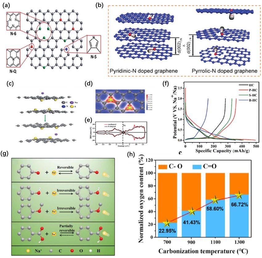
4.2. Heteroatom-doped hard carbons
The introduction of heteroatoms is considered to be an effective approach for enhancing the electrochemical
properties, surface wettability, electronic conductivity, and benefitting the charge transfer and
electrode/electrolyte interaction for carbonaceous anode materials [61, 120]. The most commonly doped
heteroatoms include nitrogen (N), boron (B), sulphur (S), and phosphorus (P), wherein the N- and
B-dopants are considered substitutional dopants, whereby these heteroatoms substitute for carbon atoms in
the lattice, while S- and P-dopants are interstitial dopants which are introduced into the interlayer spaces
[121]. The strategies for the synthesis of heteroatom-doped carbons typically include the carbonization of
heteroatom-containing precursors or the mixture of carbon precursors with heteroatom sources (in situ
13You can also read


