NEWS 221/19 - Rohde & Schwarz
←
→
Page content transcription
If your browser does not render page correctly, please read the page content below
NEWS
221/19

                                                                 Over the air
                                                                 OTA measurements are the norm
                                                                 for 5G, and they require new
                                                                 T&M solutions throughout the
                                                                 value chain

 General purpose                 Broadcast and media              Networks
High-end network analyzer sets   Quality monitoring of audio/    Automatic setup and
new standards in performance     video live streams as a cloud   management of
and operation                    service                         corporate data networks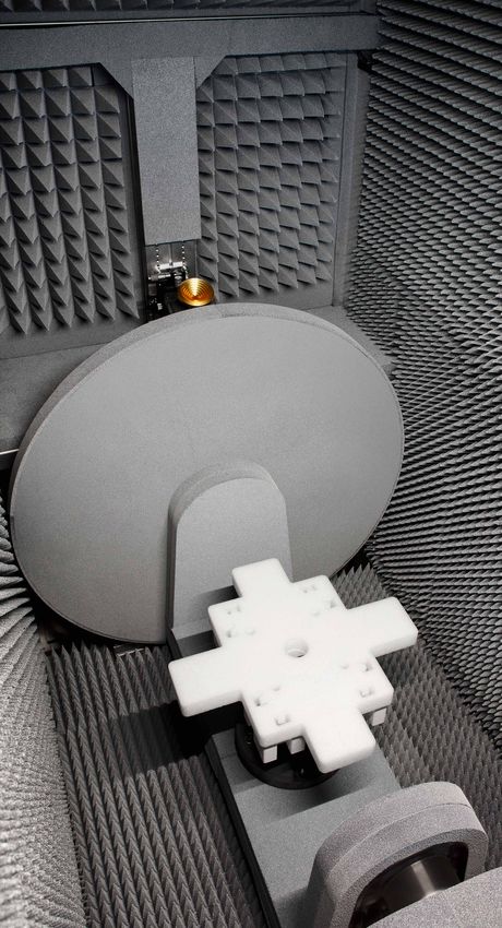
NEWS
Published by
Rohde & Schwarz GmbH&Co. KG Photos: Rohde & Schwarz
Mühldorfstrasse 15 · 81671 München Printed in Germany
www.rohde-schwarz.com Circulation (German, E
nglish, French, Spanish and Japanese)
approx. 50 000 two times a year
Regional contact
❙❙ Europe, Africa, Middle East | +49 89 4129 12345 Volume 59
customersupport@rohde-schwarz.com Issue 1/ 2019, no. 221
❙❙ North America | 1 888 TEST RSA (1 888 837 87 72)
customer.support@rsa.rohde-schwarz.com ISSN 0028-9108
❙❙ Latin America | +1 410 910 79 88 Supply free of charge through your nearest
customersupport.la@rohde-schwarz.com Rohde & Schwarz representative
❙❙ Asia Pacific | +65 65 13 04 88 Reproduction of extracts permitted if source is stated and copy sent
customersupport.asia@rohde-schwarz.com to Rohde & Schwarz München.
❙❙ China | +86 800 810 8228 | +86 400 650 5896
customersupport.china@rohde-schwarz.com PD 3609.2917.72
R&S® is a registered trademark of Rohde & Schwarz GmbH&Co. KG.
Emails to the editor: newsmagazine@rohde-schwarz.com Trade names are trademarks of the owners. CDMA2000® is a registered
trademark of the Telecommunications Industry Association (TIA-USA). The
Chief editor: Volker Bach, Rohde & Schwarz Bluetooth® word mark and logos are registered trademarks owned by the
Bluetooth SIG, Inc. and any use of such marks by Rohde & Schwarz is under
Editor and layout: Redaktion Drexl & Knobloch GmbH (German)
license. All other trademarks are the properties of their respective owners.
English translation: Dept. GF-BS2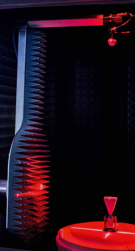
Cover feature
For development and test engineers in the mobile communica-
tions sector, the good old days of connecting devices under test
to T&M instruments with an RF cable are coming to an end. Why?
Because many new wireless products no longer have antenna connec-
tions that can be used to connect a cable. This can be attributed to
two trends: MIMO technology – a prerequisite for all future high-
performance wireless transmission methods – has made the air inter-
face a key element in device design that plays a major role in deter-
mining the performance of any wireless product. Beamforming is one
of the functions that is implemented using MIMO. Antenna measure-
ments are the only way to determine whether beamforming is working
properly. The second major trend involves communications via milli-
meterwaves. This is leading to miniaturization of antennas, which are
combined in larger numbers to form antenna arrays that are integrated
with the RF frontend to form complete units. “Over the air” is thus the
new T&M paradigm for 5G, Gigabit WLAN and other state-of-the-art
wireless systems. However, achieving the customary precision of wired
measurements with OTA turns out to be challenging. Hermetically
sealed RF-shielded test chambers that include complex mechanical
hardware will be standard equipment in the development labs, type
approval labs and factories of the future. Rohde & Schwarz has devel-
oped a complete line of these test chambers for various applications.
Given the underlying constraints of antenna physics and compared
to earlier generations of OTA test equipment, all of these chambers
are remarkably compact and deliver the field uniformity needed for
conclusive measurements in the smallest possible space (page 8). The
T&M instruments that benefit from this include the new 5G testers
from Rohde & Schwarz. The totally new platforms R&S®CMX500 (for
signaling tests) and R&S®CMP200 (for non-signaling tests) come with
their own OTA chambers (page 20). For an overview of massive MIMO,
a driving force for OTA, see our brief compendium starting on page 14.
Overview
NEWS
221/19
Cover feature Wireless General purpose
Over-the-air test solutions R&S®CMWcards graphical R&S®ZNA vector network analyzer
5G focuses on OTA............................... 8 development environment The network analyzer
Reproducibly simulating complex for today’s technology........................ 28
Small massive MIMO field tests in the lab............................ 22
compendium...................................... 14 R&S®CDS campus dashboard
R&S®FR 4 Freerider 4 walk test software
R&S®CMX500/R&S®CMP 200 system Effective teaching in
radio communication testers New walk test system electronics laboratories...................... 36
The new 5G testers............................. 20 ready for 5G networks........................ 25
R&S®FS-SNS smart noise sources
R&S®FSW85 signal and Noise factor measurement
spectrum analyzer with smart noise sources................... 40
WLAN 802.11ay:
up to 176 Gbit/s over the air............... 26
The 5G tester fleet is complete. Two new and The multichannel architecture of the new R&S®ZNA high-end vector network analyzer enables
two tried and tested platforms share the tasks simultaneous amplitude and phase measurements on up to eight signals, making it ideal for testing
(page 20). antenna arrays (page 28).
4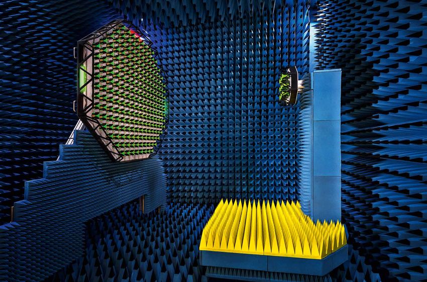
Broadcast and media Networks Satellite communications
R&S®PRISMON.cloud LANCOM Management Cloud R&S®GSACSM communication
Monitoring in the cloud...................... 42 Corporate networks simplified .......... 54 system monitoring
Monitoring and analyzing
5G Today project Network revolution gets off satellite signals................................... 62
Mobile TV reloaded.............................47 on the right foot................................. 58
R&S®DSA real-time
DOCSIS signal analyzer
Upstream measurements in Secure communications Miscellaneous
DOCSIS cable TV networks................ 50
Shortwave technology Masthead.............................................2
Three generations in the ice................ 60
NEWS compact................................. 6
Newsgrams...................................... 70
The future of audio/video monitoring is in the cloud. The new R&S®GSACSM is a software solution for monitoring and analyzing satellite
R&S®PRISMON.cloud web-based service makes it extremely easy to signals. It is ideal for operators of satcom systems, regulatory authorities,
monitor the quality of media streams (page 42). and public safety and security authorities (page 62).
| NEWS 221/19 5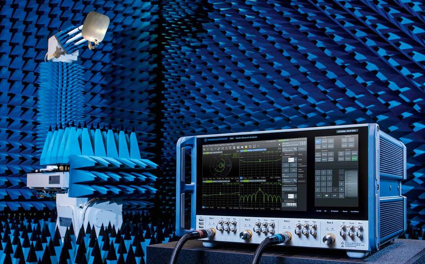
NEWS compact
First signaling tester for Bluetooth® Low Energy
Practically every communications prod- prehensive but also less complicated
uct today can connect via Bluetooth. approach to testing. This is now possi-
Bluetooth Low Energy (BLE), intro- ble with two new BLE signaling options
duced with Bluetooth version 4.0, is the for the R&S®CMW 500 wideband radio
de facto standard. For testing BLE prod- communication tester. Supporting direct
ucts, the Bluetooth Special Interest test mode (still required for certification
Group (SIG) has only specified a direct testing) as well as advertiser mode and
test mode (DTM) using a control cable. test modes for Bluetooth Classic, the
This can be a problem for manufactur- R&S®CMW platform has the widest array
ers, especially in case of very small prod- of test techniques for R&D, production
ucts such as smartwatches or IoT sen- and service applications. The BLE sig-
sors. It is practically impossible to test naling mode includes transmitter and re-
complete products of this type in their ceiver measurements up to Bluetooth
enclosure. Moreover, the cable im- version 5.0. Hopping can be restricted to
pacts the RF properties due to its prox- two channels, which is very practical for
imity to the antenna. Another problem fast production testing. Wherever possi-
is that the DTM test program does not ble, the tests are based on the DTM test
cover real operating conditions. For cases in order to produce comparable re-
example, it does not support frequency sults. SIG conformance tests in DTM are
hopping. What is needed is a more com- now a mere formality.
Mobile communications analysis system for forensic investigation
In order to check alibis or obtain informa- module for the R&S®NESTOR network
tion about possible perpetrators, police analysis suite. Combined with a network
will sometimes consult data from mobile scanner (e.g. from the R&S®TSMx fam-
network operators with the permission ily), which can be conveniently carried in
of a judge. The first case requires a traf- a backpack to the location under review,
fic data inquiry and the second a non-in- the software quickly provides a graph-
dividualized cell inquiry. Any specific in- ical/tabular overview of the local cells.
quiry can involve a large number of cells The analysis encompasses every oper-
(sometimes over one hundred) that can ator and mobile communications tech-
be received at the location in question. nology. The software ranks the different
Researching all of the cells would re- cells in terms of the probability of access
quire a great deal of effort and is not al- by a mobile phone. The investigating au-
lowed in every country. Analysis tech- thority can then make an informed deci-
niques are used to filter the cells and nar- sion about which cells to include in the
row down the possibilities for the inquiry. inquiry. This ranking often reduces the
For this application, Rohde & Schwarz de- list down to only a few cells.
veloped the R&S®NESTOR-FOR software
Virtual network analyzer
Many network analyzers are integrated inal instrument firmware, which can
into production lines, where they run be downloaded free of charge from
under program control. Until now, new the web, on a PC. For the firmware to
test programs had to be developed run, a dongle that is linked to a specific
using either a spare instrument or a line model – e ither the new top-of-the-line
instrument, which was then unavailable R&S®ZNA (see page 28) or one of the
in production during the development midrange models R&S®ZNB/C/D/BT –
work. The R&S®ZNXSIM virtual n etwork must be purchased. The complete base
analyzer eliminates this hardware re- firmware for the corresponding instru-
quirement for the user and d ecouples ments can be used. Customers wishing
software development from instrument to also program time domain measure-
availability. Basically, R&S®ZNXSIM ments such as eye diagram analyses re-
is just licensed operation of the orig- quire an additional option.
6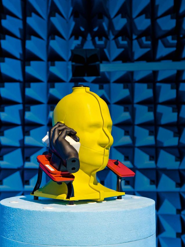
5G on the dissecting table
Everyone is talking about 5G. Many ar- out by a section on test and measure-
ticles have reported on 5G performance ment aspects. The Overall Procedures
as well as its countless potential applica- chapter examines 5G NR from the user
tions in almost every area of life. How- equipment perspective. Every aspect is
ever, the choices are few and far be- covered – from power-on through es-
tween when it comes to hard facts about tablishment of a data connection to the
5G technology. A new English-language processes that occur during mobility
book from Rohde & Schwarz is helping to in the network. The description of non-
fill this gap. Five of the company’s mo- standalone (NSA) mode, which will be
bile communications specialists provide used for mixed operation with LTE dur-
in-depth insights into the 5G NR system ing 5G’s initial phase, is followed by a
in this 460-page work. The Fundamen- chapter on 5G standalone (SA) mode.
tals chapter examines the system archi- The highly illustrated hardcover edi-
tecture and physical access techniques. tion is available from booksellers (ISBN:
This includes detailed treatment of ad- 978-3-939837-15-2). A regularly updated
vances vis-à-vis the 4G system in areas online version is available free of charge
such as beamforming and bandwidth after registering (see QR code).
segmentation. The chapter is rounded
Power sensors for waveguide systems
Waveguide sections are widely used principle, which always produces true
in millimeterwave applications due to RMS values regardless of signal shape.
their low transmission losses. Test in- The sensors are thus suitable for signals
struments for use with waveguide sys- with any kind of modulation. Across the
tems should also have a waveguide fron- entire 55 dB dynamic range (–35 dBm
tend, since a waveguide-to-coax tran- to +20 dBm), the sensors rapidly reach a
sition would diminish the accuracy and stable measured value (e.g. in less than
dynamic range. To satisfy this need, one second at –10 dBm). The waveguide
Rohde & Schwarz has extended its line sensors also have all of the usual bene-
of power sensors with some new mod- fits of the R&S®NRP power meter fam-
els. The R&S®NRPxxTWG sensors for the ily. They can be used alternatively on the
ranges from 50 GHz to 75 GHz (WR15 R&S®NRX base unit or connected via
connector), 60 GHz to 90 GHz (WR12) USB to a computer or test instrument.
and 75 GHz to 110 GHz (WR10) cover di- With their plug & play design, they are
verse applications involving satellite, ra- immediately ready for operation with no
dar and communications technology. calibration required. For customers who
Unlike other commercial solutions that require extremely high accuracy, the sen-
use diode rectification, the new sen- sors can be traced back to national cali-
sors are based on the thermal measuring bration standards.
Advanced TV and DAB transmitter technology for the VHF band
With thousands of transmitters sold, the adaptive efficiency optimization that
the R&S®THx 9 is the most success- is implemented, network operators can
ful family of high-power TV transmitters benefit from high efficiency even after
in the world. The success of this prod- the transmission parameters are modi-
uct line is due to its unique combina- fied. Besides their energy cost savings,
tion of economical operation, conve- the digital exciter is another major bene-
nience and future viability. The latest de- fit of these transmitters. The purely soft-
velopment stage (Evo) was initially fo- ware-based exciter makes it possible to
cused on UHF transmitters, but net- fully exploit the flexibility of new stan-
work operators can now also enjoy supe- dards such as ATSC 3.0 – even includ-
rior technology for the VHF range (band ing future developments. The MultiTX
III) with the R&S®THV9evo. The liq- concept allows multiple transmitters to
uid-cooled transmitters are available for be installed in a space-saving manner in
DTV and DAB with output power from a single 19" rack. Despite all of their so-
1.3 kW to 30 kW. They feature high en- phistication, the transmitters are easy to
ergy efficiency of up to 50 %. Thanks to operate using the pull-out touch display.
| NEWS 221/19 7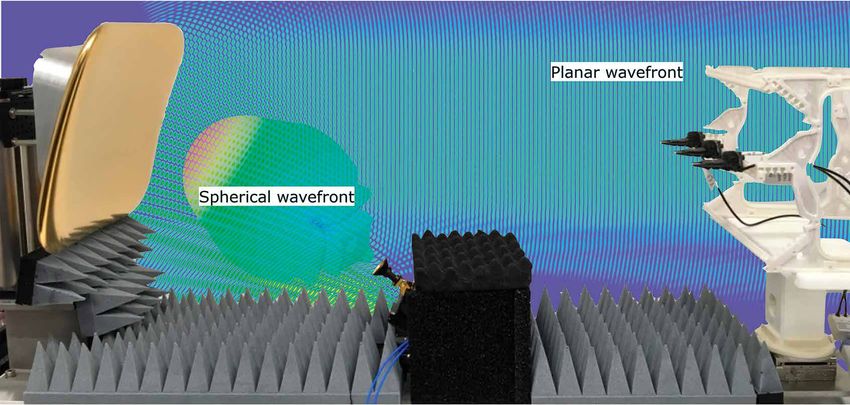
Wireless

5G focuses on OTA

             In chambers of this size (type Albatross WPTC-XL), antennas
             larger than the model shown here (black DUT with tapered white
             holder) can be tested. For far-field conditions, however, this
             chamber is too small, which is why mathematical near-field to
             far-field transformation is necessary.

8
In 5G, highly integrated massive MIMO antenna systems that support beam-
forming are superseding classic sector antennas. These systems must be character-
ized over the air – a challenge for T&M manufacturers and system developers alike.

Achieving the needed high channel capacity in a 5G net-            Antenna characteristics are generally measured in the homo-
work requires rolling out massive MIMO base stations along         geneous far field (FF). However, far-field conditions at FR2 fre-
with networks and mobile stations implementing both micro-         quencies for base station antenna sizes do not begin until
wave and millimeterwave technologies. In 5G, the microwave         a distance of many meters from the antenna. Using direct
range is designated as frequency range 1 (FR1, 410 MHz             FF probing and applying the Fraunhofer distance (FHD) cri-
to 7.125 GHz) and the millimeterwave range as frequency            terion for the far field (r = 2D²/λ, D is the antenna aperture),
range 2 (FR2, 24.25 GHz to 52.6 GHz).                              a 75 cm massive MIMO device under test (DUT) radiating
                                                                   at 2.4 GHz would require a test chamber with a range of at
In FR1, the main innovation effort is on the base station (BS).    least 9 m. Even a 15 cm smartphone transmitting at 43.5 GHz
Active arrays (massive MIMO arrays) are deployed that can          would require a testing distance of 6.5 m. This distance is
have hundreds of antenna elements. Massive MIMO has two            required to create a region encompassing the DUT, the quiet
objectives. First, it allows the generation of multiple inde-      zone (QZ), with the necessary phase constancy. The imping-
pendent data streams for simultaneous coverage of multi-           ing field must be as uniform as possible and approach a plane
ple mobile stations (multi-user or MU-MIMO). Second, beam-         wave with phase deviation below 22.5 °.
forming can be used to direct these streams at specific
remote stations. This focuses the energy in order to increase      Theoretical research shows that actual FF behavior in the
the coverage area, reduce interference and boost the data          peak directivity region can start much closer in than the FHD.
rate. There is also a bonus side effect of lower energy con-       Research results proved, for example, that the FF EIRP or EIS
sumption, which reduces overall network costs.                     of a 15 cm DUT radiating at 24 GHz can be accurately deter-
                                                                   mined at a distance as short as 1.14 m. This distance reduc-
In FR2, the transmission systems use large available band-         tion of about 70 % is achieved at the cost of increased longi-
widths at frequencies around 28 GHz and 39 GHz. These              tudinal taper error. Also, side lobe levels cannot be evaluated
high frequencies lead to high path loss based on the formula       accurately at shorter distances.
F = (4πrf/c) 2 and large electromagnetic field absorption in
nearby objects. Array antennas with their improved gain help       While direct FF measurements at shorter distances are not
reduce this loss.                                                  practical for all applications, they are beneficial in cases
                                                                   where the necessary conditions are met. This is because large
                                                                   anechoic chambers have high costs of ownership and limited
Performance metrics quantified over the air                        dynamic range due to the path losses. The simplest scenario
In FR2, the need for low path losses and small dimensions          is the “white box” case where the antenna location within the
is leading to highly integrated solutions combining antennas,      device and its aperture size are known and the aperture fits
modems, amplifiers and phase shifters. Consequently, there         entirely within the QZ. If this is not the case or if the DUT has
are no longer any RF contacts for connecting test instru-          multiple antennas situated on opposite edges of the enclo-
ments via cables. This is why over-the-air (OTA) test solutions    sure, then we have the “black box” scenario where the radi-
are needed in order to characterize the transmit and receive       ating currents can flow anywhere within the DUT. Due to the
antennas. Such solutions are also needed to verify whether         potentially larger aperture, a significantly larger QZ must be
the transmission lobe is pointed in the right direction.           implemented, making direct FF measurements difficult. For
                                                                   such situations, we can employ near-field to far-field transfor-
The metrics to be determined include antenna parameters for        mations (NFFF) as an alternative.
the radiated and received power such as the effective isotro-
pic radiated power (EIRP), total radiated power (TRP), effec-
tive isotropic sensitivity (EIS) and total isotropic sensitivity   Software NFFF transformations
(TIS). There are also transmitter-specific metrics such as the     A first efficient approach for reducing the FF distance (and
error vector magnitude (EVM), adjacent channel leakage ratio       thus the necessary size of the shielded chamber) involves
(ACLR) and spectrum emission mask (SEM).                           the use of software transformation methods. The mathe-
                                                                   matical implementations may vary, but the concept is gen-
                                                                   erally the same: at least two polarization components of the

                                                                                                                  | NEWS 221/19 9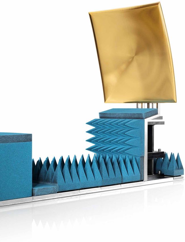
Wireless
electromagnetic field (E, H or a mix-
ture of the two) are measured in magni-
tude and phase over a spherical surface
encompassing the DUT.
The measured data is processed using
mathematical functions to propagate
the fields towards larger distances and
extract far-field radiation components.
From the Huygens principle, the knowl-
edge of two phasors (complex ampli-
tudes) is enough to reconstruct exactly
all six field components outside the sur-
face. Alternative transformation meth-
ods use spherical wave expansion
(SWE), plane wave expansion (PWE)
or integral equation resolution, along
with techniques to improve computa-
tional efficiency or accuracy by taking
parameters such as the spatial sampling
rate, scanning area or truncation into
account.
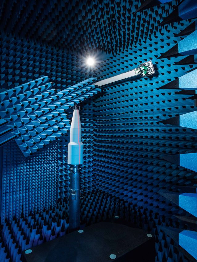
Fig. 1 shows a system capable of mea-
surements using spherical scanning
around the DUT. The DUT is positioned
on a turntable rotating in azimuth.
A dual-polarized Vivaldi antenna is
mounted at the tip of a boom rotating in
elevation. The DUT is connected to one
Fig. 1: The R&S®ATS1000 is an example of port of a vector network analyzer (VNA).
a spherical measuring system that supports The antenna ports for the two polariza-
both direct far-field measurements and soft- tion planes are connected to two other
ware-based near-field to far-field transforma- VNA ports, enabling measurement of
tion. The DUT can be precisely positioned with complex S-parameters such as the
the aid of a laser. The system can be equipped transmission and reflection coefficient.
with a hemispherical climatic chamber that fully
encloses the DUT and allows measurements Near-field measurement methods often
under climatic stress across a wide tempera- rely on assumptions applying to this
ture range. above-described case of “passive or
RF-fed antenna testing”:
❙❙The antenna feed port is accessible
with a signal fed to the antenna that is
used as phase reference
❙❙The RF signal is a continuous wave
(CW) signal
❙❙ Reciprocity applies so that transmit
(TX) and receive (RX) patterns are iden-
tical at the same frequency
There are workarounds available in
TX cases where such assumptions
do not apply. Hardware and process-
ing implementations to retrieve the
10propagation phase vary, for example using interferometric Hardware-based near-field to far-field
techniques or multi-port phase-coherent receivers, with the transformation provides clarity
addition of a dedicated phase reference antenna that has Different testing methods enable direct OTA assessment close
to be installed in the vicinity of the radiating DUT. Alterna- to the antenna without applying a software transformation.
tive approaches include phaseless methods where the phase In these hardware approaches, the idea is to physically cre-
information is retrieved from magnitude-only measurements. ate far-field conditions in a specified quiet zone (QZ) region
within a short range. This “indirect far field” can be created in
The RX case is more complex because usually the entire a compact antenna test range (CATR) or by using plane wave
RX chain must be measured since the sensitivity is veri- synthesis.
fied based on attainment of the minimum required data
throughput. The reciprocity assumption does not apply since Compact antenna test range
the RX RF component chain is in general different from A CATR uses a parabolic reflector to transform a spheri-
the TX RF chain. Furthermore, for a receiving DUT with no cal wavefront from the DUT into a planar wavefront (Figs. 2
antenna test port, the power available at the input to the and 4). The quality of the measurement results that can be
RF frontend cannot be straightforwardly predicted. There is obtained with a CATR depends on the reflector quality. The
also no access to a phase reference in this case so that the edge shape and surface roughness influence the frequency
software NFFF transformation becomes inapplicable. There- range in which an acceptable quality quiet zone can be pro-
fore, effective isotropic radiated power (EIRP) can be evalu- duced. The edge configuration limits the lowest operating fre-
ated accurately in the near field using software NFFF but not quency while the surface roughness determines the upper
effective isotropic sensitivity (EIS). frequency. Serrated or rolled edges prevent diffraction that
could otherwise significantly contaminate the QZ. The reflec-
Software NFFF methods reach their limits when attempting to tor size with serrated/rolled edges is generally at least two
determine transceiver metrics such as EVM, ACLR and SEM. times the DUT/QZ size whereas a reflector with sharp edges
Such information must be extracted directly from the modu- is three to four times the size of the QZ.
lated signal. However, software NFFF solutions only process
the complex amplitude values used to derive a three-dimen-
sional representation of the antenna characteristics. Using
advanced T&M methods, however, this is not a major limita-
tion since compact measuring systems can create an “indi-
rect far field”, allowing measurements to be performed that
are comparable to the true far field.
Fig. 2: The reflector’s shape and
manufacturing precision are impor-
tant quality parameters in a CATR
system. The R&S®ATS800B CATR
benchtop system is a cost-effec-
tive solution for development and
research laboratories that need
high-quality measurement results.
| NEWS 221/19 11Wireless
The feed antenna’s radiation pattern
has a direct impact on the size of the
QZ since the reflector essentially “proj-
ects” the pattern onto the QZ. Since the
QZ size depends more on the reflector
characteristics than on how far the DUT
is from the reflector, it is much easier
to create a large QZ inside small enclo-
sures, which makes testing simpler. The
CATR test setup shown in Figs. 2 and
4 fits inside a chamber measuring only
2.1 m × 0.8 m × 1 m (R&S®ATS800R).
A direct FF measuring system would
require a range of up to 14.5 m.
CATRs are of great interest for test-
ing mobile and base stations operat-
ing in 5G NR FR2 since they consider-
ably reduce the size of the test envi-
ronment and produce measurement
results directly, i.e. without any further
NFFF computations. In addition, CATRs
have the same capabilities as an FF sys-
tem in terms of direct measurements of
RF transceiver metrics in both TX and
RX mode. Finally, since the path loss of
such a system only occurs in the region
between the feed and the reflector, the
dynamic range of a CATR system is
also improved compared to a direct
FF approach.
Fig. 3: The R&S®ATS1800C test chamber is
used for (pre)conformance testing of reference
designs and mobile devices. The positioner can
accommodate DUTs with sizes up to about
DIN A4 and weighing up to several kilograms.
12Plane wave synthesis using a software transformations are suitable also provide compact and reliable alter-
phased antenna array for evaluation of EIRP and TRP quan- natives to direct far-field measurements,
While CATRs can be built for 5G milli- tities. When RX or demodulation is putting them in pole position for future
meterwave DUTs using relatively com- involved with a DUT using multiple non- 3GPP RF conformance testing of mobile
pact and lightweight reflectors (20 kg identical RF transceivers, methods uti- devices and base stations.
to 40 kg), the reflector weight increases lizing hardware field transformations Dr. Benoît Derat, Dr. Corbett Rowell,
significantly in FR1 – up to hundreds such as CATR and PWC can overcome Dr. Adam Tankielun, Sebastian Schmitz
of kilograms for DUTs the size of base the limitations of software NFFF. They
stations. The cost, fabrication time and
handling of the large, heavy reflectors
becomes prohibitive. An “electronic ver-
sion” offers a lightweight, cost-effec-
tive alternative. It consists of an antenna
array with multiple elements that are
individually controlled in amplitude and
phase to produce a planar wavefront
starting at a relatively short distance.
Rohde & Schwarz has developed such a
planar wave converter (PWC) consisting
of 156 wideband Vivaldi antennas and
a network of phase shifters and atten-
uators. This PWC array is 1.7 m wide
and creates a spherical QZ of 1 m diam-
eter at a distance as short as 1.5 m in
the frequency range from 2.3 GHz to
3.8 GHz (Fig. 5). A combined-axis posi-
tioner is used to position the DUT (e.g. a Fig. 4: Compact antenna test range (CATR) with a roll-edged reflector collimating a spherical wave-
base station antenna) in the QZ. In the front into a planar wavefront (fields computed with a model of the actual setup implemented in the
figure, the DUT is a calibration antenna CST MWS simulation software at 28 GHz).
that is used to control the levels of indi-
vidual RF channels as well as to deter-
mine the path loss of the entire test sys-
tem. The PWC is reciprocal and has only
one RF input/output, which can be con-
nected to a signal generator, spectrum
analyzer or vector network analyzer.
Summary: OTA measurements
are simpler than ever
The need to test 5G components over
the air requires new, more sophisticated
measuring equipment than previous
mobile communications technologies.
The challenge for T&M manufacturers is
producing such equipment at competi-
tive prices while ensuring simple oper-
ation. The solution is a measuring sys-
tem that can reliably assess the behav-
ior of a DUT in the far field without hav-
ing to install large shielded chambers Fig. 5: The heart of the plane wave converter measuring system from Rohde & Schwarz is the
that satisfy the Fraunhofer far-field cri- R&S®PWC200 phased array (left). In place of the DUT is a calibration antenna array mounted on a
terion. Near-field techniques employing great circle cut positioner.
| NEWS 221/19 13Wireless
Small massive MIMO compendium
What is massive MIMO? Spatial multiplexing: M data streams
Multiple input multiple output (MIMO)
technology uses multiple antennas at x1(t)
M = 4 transceivers
the transceiver to improve transmis-
x2(t)
sion performance. Either multiple trans-
ceivers transmit via separate antennas
x3(t)
over uncorrelated propagation paths to
achieve higher throughput for one or x4(t)
more users (spatial multiplexing), or the
same output signal is transmitted via +
multiple antennas and combined in the Beamforming array: 1 data stream
receiver to improve the signal quality
(RX diversity).
Thanks to the large number of antenna
elements in massive MIMO systems, x1(t) TRX
both concepts can be combined. An
antenna system that supports beam-
forming as well as spatial multiplexing
is known as a massive MIMO system.
Although massive MIMO is applied only
in base stations, wireless devices are Massive MIMO: combining beamforming with spatial multiplexing results in
also using increasing numbers of anten- MU-MIMO for M wireless devices
nas to implement MIMO techniques.
Massive array with 128 to 1024 active antenna elements
Multi-user MIMO (MU-MIMO)
Improved SNR and higher data rate for each user, e.g.
UE 1: 32 antennas, beamforming with 16 × n MIMO
UE 2: 16 antennas, beamforming with 8 × n MIMO
Why massive MIMO? path attenuation. Massive MIMO in transmit spatially separated streams for
Beamforming with massive MIMO the FR1 range will be primarily used to multiple receivers (MU-MIMO).
focuses the transmitted energy, effec-
tively increasing the energy efficiency Massive MIMO improves energy efficiency and throughput rate
– an important aspect when operat- Traditional base station antenna Massive MIMO antenna array
ing a mobile communications infra-
structure since radio transmissions are Wasted power
the main contributor to energy costs.
Beamforming also increases the range
..
and reduces interference between cells. Wasted power .
Range is very important at 5G millime-
terwave frequencies due to the high
14Technical challenges of Data bottleneck Calibration
massive MIMO
Massive MIMO is a sophisticated con- Cloud
cept that requires system designers to
solve a number of problems.
Ideal pattern
Higher connection costs Reduced MU-MIMO
Resulting pattern
The high data throughput of a massive MIMO Antenna arrays that have not been properly
system requires an ultra wideband connec- calibrated can radiate in unwanted directions.
tion between the base station and the core This beam squinting means less than optimal
network. coverage for the receivers.
Mutual coupling Irregular arrays Complexity
RX
RFIC RFIC
FPGA
Digital I/Q
Reduced capacity Grating lobes Increased costs
Mutual coupling between antenna elements In practice, some antenna arrays will need to Massive MIMO systems represent a new
leads to energy loss and thus a reduction in be designed with non-geometric shapes that level of complexity from a design, manufac-
the maximum range. may result in dissipating energy in undesired turing, calibration and deployment perspec-
directions. tive. This level of complexity requires new
approaches to design and testing.
Different small amount of hardware makes this array is connected to one RF chain gen-
beamforming techniques a cost-effective method for building a erating only one beam at a time, and
In order to achieve a certain directivity beamforming array of lower complex- the range of the phase shifters limits the
with antenna arrays, the amplitudes and ity. Typically, an analog beamforming applicable frequency range.
phases of all antenna elements must
interact in a defined way. There are Analog beamforming
three possible approaches.
PA
Analog beamforming
The traditional approach, used for exam- PA
Data stream Baseband
ple in radar applications, uses phase processing
. PA
.
shifters and power amplifiers to steer .
the beam into the desired direction and
PA
reduce the sidelobes to a minimum. The
| NEWS 221/19 15Wireless
Digital beamforming Digital beamforming
This more advanced architecture is not
actually used to steer beams. Instead, Data
stream 1 Digital
it optimizes coverage of the different baseband RF chain
receivers with individually computed processing
path streams. Each antenna has its own .. .. ..
transceiver and data converters, allow- . . .
ing it to handle and generate multiple
Data
independent data streams. The base stream n
Digital
station and wireless device form a con- baseband RF chain
processing
trol loop where the BTS uses pilot sig-
nals from the wireless device to con-
tinuously adjust the precoding matrix
for that device. Each receiver there-
fore receives perfectly tailored signals Hybrid beamforming
via diverse paths. This type of feed-
back control works best in TDD systems
where the radio channel is reciprocal in Digital ... PA
baseband RF chain
the uplink and downlink. processing
K data .. .. .. PA ..
streams . . . .
Hybrid beamforming
Hybrid beamforming balances the cost
Digital
baseband RF chain
... PA
and performance advantages and dis- processing
advantages of analog and digital beam- PA
forming. Targeting higher frequency Digital beamforming Analog beamforming
ranges, such designs combine analog
beamforming arrays with digital prepro-
cessing stages.
Typical setup for near-field antenna testing
R&S®ZNA
vector network analyzer Antenna near field
Measurement antenna
How do you connect the
antenna array in a test setup? Antenna
system
The directivity of antenna arrays requires (AUT)
an over-the-air (OTA) test setup. Pas-
sive antennas use the traditional test-
Reference
ing approach in which the generator in antenna
a vector network analyzer (VNA) sup-
plies a signal to the antenna under test.
The signal from the AUT is received by
the measurement antenna and fed to
a receiver port on the VNA. This test is
straightforward to implement and deliv-
ers comparable results.
16Massive MIMO antennas, on the other One possible workaround is to steer Measurements in the near field are very
hand, are integrated together with sig- a beam by using a smaller number time-consuming and do not deliver all
nal processing and RF circuitry to form of neighboring antenna elements to of the relevant parameters. It is faster
complete units that are connected to reduce the antenna aperture, which and more universal to perform mea-
the base station via a digital interface allows a far-field scenario to be created surements in the quasi far field, but this
such as CPRI. As a result, the phase of in a test chamber under certain circum- requires more complicated test equip-
the emitted signal cannot be accessed, stances. Near-field test solutions from ment (see below).
but this information is crucial in order to Rohde & Schwarz are based on a refer-
convert near-field measurements to far- ence antenna (field probe) positioned at
field data. a constant distance to the AUT, provid-
ing a reference phase.
Near field or far field? near field depend on magnitude and field estimation. One of these methods
The distance between the antenna phase and require complicated postpro- is based on power measurements at dif-
under test (AUT) and the measure- cessing to convert the data to the far ferent distances. Another approach is
ment antenna is crucial for OTA mea- field. The data comes from sample mea- based on the half-power beamwidth
surements. Electromagnetic coupling surements on specific trajectories or on that reduces the aperture size D to the
with intruding objects such as measure- a spherical surface around the AUT. The size of the “radiating part” D* that is
ment antennas at a distance smaller test setup has to have a 3D positioner typically smaller. A further approach
than the first Fresnel zone (typically only to allow the measurement antenna to considers that only the main beam is
a few centimeters) occurs in the very access every point on the sphere. of importance for measurands such as
near field, or reactive field, which is why EVM, resulting in a significantly reduced
measurements are not possible here. Rohde & Schwarz has proposed addi- distance between the AUT and the mea-
Measurements in the adjacent radiated tional methods for near-field and far- surement antenna.
Measurement aspects in the near field and far field
Near-field measurements
❙ Smaller chamber sizes
❙ Values depend on phase and magnitude –
difficult for modulated signals
❙ Requires near-field to far-field (NFFF) transformation
❙ Requires multiple samples –
additional time and effort
❙ Single antenna probe approach:
requires accurate positioner
❙ Multi-antenna probe approach:
complex calibration
Far-field measurements
❙ Larger chamber sizes
❙ Values depend on magnitude only –
good for modulated signals
❙ One sample is sufficient –
no NFFF postprocessing
Reactive Radiated near-field region = Far-field region =
field phase and magnitude magnitude
1)
D3 2D 2
0,62
λ λ
1)
Typically for radiators with D > λ/2
| NEWS 221/19 17Wireless
How do you create far-field The idea of using Fresnel lens (Fourier optics)
conditions at short distances? a Fresnel lens is
Theory recommends testing antenna well known in the
optical world. In
arrays under far-field conditions, espe-
the RF world, this
cially when performing EVM measure- method is rather
ments, since the phase varies in the complex and Quiet zone
near field. The easiest method of gener- involves high costs,
ating far-field conditions is to extend the making it unfeasible
distance between the AUT and the mea- for industrial appli-
cations. AUT
surement antenna as described by the
Fraunhofer diffraction. For large arrays,
however, this can lead to distances of
dozens of meters. Therefore, near-field
to far-field (NFFF) transformation meth-
ods are commonly used.
Compact antenna test ranges (CATR) are well known in the industry. Reflector (CATR)
A reflector is used to generate a cylindrical quiet zone – a zone where
the observed phase difference to a plane wavefront is below a user-
specific tolerance. The reflector size is typically around two to three
times the diameter of the quiet zone. The roughness of the reflector
surface should not exceed a value of about λ/100 (approx. 0.1 mm for
Quiet zone
the FR2 range of 5G). In order to attain high field quality in the quiet
zone, the reflector edges must be either serrated or rolled.
AUT
Wave synthesis with an antenna array is an elegant way of generat- Plane wave converter (PWC)
ing a homogenous field in a very small space. Rohde & Schwarz devel-
oped such a solution for sub6 GHz frequencies: the R&S®PWC200
plane wave converter. It uses phase shifters and an octagonal 1.7 m
diameter antenna field to generate a spherical quiet zone with a diam-
eter of 1 m at a distance of 1.5 m, allowing operation under tight Quiet zone
space constraints in laboratories.
AUT
18T&M equipment for massive Test setup based on a plane wave converter for antenna arrays
MIMO components
Massive MIMO testing covers a wide Passive measurements
range of applications, taking into 2D/3D antenna characterization
account technical aspects such as near
System and
field, far field, frequency, antenna type AUT control
and parameters to be tested. Test con-
figurations and tests considerably dif- R&S®AMS32 OTA performance
fer when testing in R&D, manufactur- measurement software R&S®PWC200
plane wave converter
ing and in the field. Upcoming applica-
tion areas such as beamforming cer-
tification and verification and produc-
tion-oriented testing will generate new R&S®ZNA RF cable
requirements when it comes to accu- vector network analyzer
racy, speed, costs, etc. 1.5 m
Active measurements
RF transceiver characterization:
There are four key components to any adds RF measurements on
massive MIMO measuring system: modulated signals, e.g. EVM
AUT: high-gain
System and antenna array
Shielded chamber AUT control
Various sizes to cover near-field and far-
field aspects, shielding and absorption R&S®AMS32 OTA performance
capability, chamber access, etc. measurement software
Measurement antenna
Key considerations are frequency range, R&S®SMW200 A
size and calibration. vector signal generator
AUT fixture and measurement
antenna positioner
R&S®FSW signal and
A spherical pattern measurement spectrum analyzer
around the AUT is required to measure
parameters such as EIRP, EIS and TRP.
The measurement quality depends on
factors such as the precision and repro-
ducibility of positioning the measure-
ment antenna.
T&M equipment A white paper providing detailed
The required T&M equipment depends information about OTA test
on the specific measurement task. A and measurement solutions
typical massive MIMO test system can be downloaded from the
includes vector network analyzers, sig- Rohde & Schwarz website.
nal generators, signal analyzers, wire-
less communications testers and power
sensors.
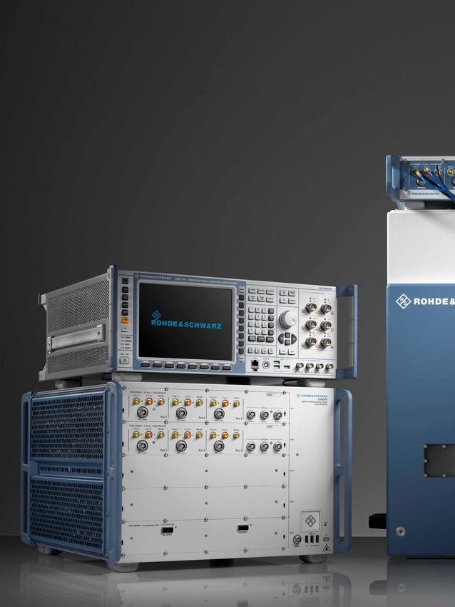
| NEWS 221/19 19Wireless The new 5G testers Testing 5G NR products requires new test and measurement The R&S®CMX500 radio communication tester (bottom approaches. Technologies such as massive MIMO, substan- left) is the new test platform for signaling tests in all 5G fre- tially higher bandwidths and data rates than in 4G, and the quency bands. It works together with the tried and tested use of millimeterwaves have greatly increased the necessary R&S®CMW500 tester (top left) to provide support for mixed computing power while making OTA measurements com- operation with LTE (5G NSA), which will be predominant pulsory and creating challenging requirements for RF hard- worldwide in the first years. ware. In the future, the following testers will be workhorses for 5G measurements in development, QM acceptance test- ing and production: 20
Measurements in the FR2 range (mmWave) are performed             (sub6 GHz spectrum), the R&S®CMW100 tester is the right
in OTA test chambers such as the R&S®CMQ200. In combi-           choice (not shown). The R&S®CMX500 and R&S®CMP200 are
nation with the new R&S®CMP200 non-signaling tester (top         operated via unified test software (right). The software pro-
center), it provides a compact solution for production testing   vides access to the measurement functions via a browser-
of 5G FR2 components. For production tests in the FR1 range      based user interface.

                                                                                                            | NEWS 221/19 21
Wireless Reproducibly simulating complex field tests in the lab New options boost the quality of field test approximation for mobile devices in the R&S®CMWcards graphical development environment. The test cycle of a mobile device starts with testing individ- Convenient field-to-lab signaling for ual signaling functions and ends with field tests in the opera- R&S®CMWcards tional network of the operator. Field tests are the most mean- R&S®CMWcards on the R&S®CMW platform provides a high- ingful in terms of the end user experience, but they are also performance development environment for test cases for the most time-consuming and costly. In addition, they are not mobile communications standards from 2G to 4G (Fig. 1). The always reliably reproducible in all details because operational tool does not require a programming language. Test cases networks are constantly changing. This makes troubleshoot- can be created using a graphical user interface, merged into ing more difficult. test sequences and performed automatically. Another challenge is testing the interaction of embedded The R&S®CMW-KT030 field-to-lab option imports signaling modules with the higher-level system. This can lead to mal- data from drive test log files into R&S®CMWcards. It extracts functions that cannot be verified by testing the components MIB/SIB messages, cell properties, RRC configurations and separately. For drive tests, mobile communications devices in NAS configurations. It can import files from Rohde & Schwarz passenger vehicles and telematics applications in the logis- tools such as R&S®QualiPoc, R&S®ROMES and R&S®Nestor. It tics industry are especially relevant. Smooth interaction of all supports the Open Log open interface and the log formats of modules in mobile systems is considerably more important chip manufacturers such as Qualcomm, Intel and MediaTek. with 5G since time-critical low latency applications can also This data can be used to simulate local network scenarios at be implemented with the new standard. A test solution that combines the advantages of lab tests and field tests would be ideal. The R&S®CMWcards test suite now offers developers and test engineers two modules that make measurement data from the field accessible for laboratory analysis. Fig. 1: R&S®CMWcards on the R&S®CMW500 platform. 22
the logic level. Another option allows you to simulate specific                           Drive tests can last several hours, generating a correspond-
RF conditions at the measurement site where the data was                                  ing volume of recorded log files. But testers and developers
collected.                                                                                are usually only interested in short sections of the drive test.
                                                                                          Therefore, predefined filters are used to identify relevant infor-
The R&S®CMW-KT 041 RF power replay option processes the                                   mation in the imported data.
RF data from the log files. Fig. 2 shows the overall field-to-lab
workflow.

 Field-to-lab workflow

                                                         Network                          UE (DUT)

                                                                                                Rohde & Schwarz scanners
        GSM         WCDMA                   LTE                                                 can record MIBs and SIBs
                                                                                                without signaling                                       Reproduction of the
                                                             Master information block (MIB)
                                                                                                                                    Log file             recorded field tests
                                                             System information block (SIB)                                         import              with the R&S®CMW500
                                                                                                                                                        wideband radio
                                                             SIB2
                                                                                                                                                        communication tester
                                                               ●●●

                                                               ●●●                              Chipset or UE logging tools
                                                                                                can enable access to the
                                                                                                signaling process and         Log
                                                                                                record the messages in        file                            Simulation of a
                                                                                                                                                             mobile network
                                                                                                their entirety
                                 Recording of layer 3        Layer 3 signaling messages                                             Creation of test cases
                                 signaling and RF                                               e.g. R&S®ROMES or                   with R&S®CMWcards
                                                             NAS
                  Log            conditions with                                                UE logging tools                    using an imported
                  file                                        RRC                                                                    network configuration
                                 drive test tools such                                          such as QXDM
                                 as R&S®ROMES or
                                                               ●●●
                                 with UE chipset
                                 logging tools                 ●●●

                                                         Network                          UE (DUT)

Fig. 2: Field-to-lab workflow from the field test to the lab test.

Fig. 3: List of selected cells with respective log data.

                                                                                                                                                       | NEWS 221/19 23
Wireless
Fig. 4: The recorded RF levels of the selected cells plotted in the time domain.
Extensive filter and analysis tools are used to select relevant With the network profiles obtained from the field tests, the
cells (together with their cell data and message types) from test plans in R&S®CMWcards, e.g. for regression tests, can
the list of recorded events. The information they contain, such be reused in test suites for specific network operators. This
as MIBs/SIBs and RRC procedures, is listed (Fig. 3) and the is done by simply dragging and dropping the network pro-
corresponding RF levels are shown on a graph (Fig. 4). file onto a test case or a test campaign. The test case maps
that are changed by the network profile are marked, making
Network profiles can be created from the selected cells and it easy to understand and adjust the operator-specific modifi-
cell parameters and incorporated in signaling sequences of cations. This enables improved prequalification for field tests
test cases defined in R&S®CMWcards. The scenarios can be and reduces the probability of errors in future drive tests.
augmented with the RF parameters measured in the field so
that lab procedures such as registration and cell selection/ The R&S®CMW-KT030 field-to-lab option and R&S®CMW-KT041
reselection are performed with exactly the same network and RF power replay option in R&S®CMWcards provide a compre-
cell parameters as in the field test. Even handover and out-of- hensive and convenient toolset that can greatly reduce the
sync scenarios are realistically simulated with the recorded number of test drives necessary for mobile devices, and effi-
RF levels. ciently simulate and resolve errors in the lab. The test cases
can easily be integrated into regression suites, increasing the
For error analysis, R&S®CMWmars provides an extensive quality of future versions of the mobile devices before the first
and proven toolkit for processing test logs that drastically field tests. Plans are in place to extend the field-to-lab option
reduces the time needed to identify the cause of the error in by adding RF aspects and the creation of complete fading
the field test. profiles based on the Doppler shift and delay data from field
test measurements. A 5G enhancements is also planned for
the near future.
Dr. Wolfgang Kalau
24In brief
New walk test system
ready for 5G networks
Freerider walk test systems have been used for years now as part out. This frequency range (24 GHz to 30 GHz) is covered by the new
of quality test campaigns for mobile communications, e.g. in the R&S®TSME30DC downconverter, which has five IF outputs for feed-
New York City subway. These systems automatically provide quality ing the same number of scanners. The measurement software trans-
data that is accurate to the meter for all receivable mobile commu- parently integrates the downconverter, so the user does not have to
nications services. This is especially relevant in places that are only worry about any settings. A single scanner plus downconverter is
accessible on foot, such as shopping centers, airports, stadiums and enough to perform nearly simultaneous measurements on all network
pedestrian zones. Results of this kind are appealing to network oper- technologies, including the 5G bands. Fast switching is performed
ators who need to compare performance with the competition – as between the millimeterwave and FR1 range. Customers requiring real-
well as to users, who in many cases rely on measurement results time performance or a wider dynamic range, or who wish to perform
published in major test magazines when choosing a provider. 4×4 MIMO measurements in LTE, can connect additional scanners.
The inner workings of the R&S®FR4 Freerider 4 (Fig. 1) have been fully The Freerider 4 is easy to operate via a tablet or notebook connected
redesigned compared with version 3. Up to 12 test smartphones can to the system computer via Wi-Fi. The actual measurement soft-
now be used to simultaneously gather data and transfer it to the sys- ware depends on the specific application. For benchmarking cam-
tem computer. Such analytical power is sometimes needed for simul- paigns, SmartBenchmarker comes into play, while the powerful
taneous testing of different quality criteria in multiple networks. Video R&S®ROMES4 analysis suite is used primarily for network optimiza-
and voice quality measurements require a certain amount of time and tion. Public authorities can use R&S®NESTOR, e.g. for crime scene
should not slow down any other concurrent measurements. In addi- forensics (see p. 6).
tion to these quality of service criteria, it is important to determine
on-site RF conditions. If the field strength is too low or interference is During measurements, there is no need to take hold of the backpack.
occurring, a local service quality drop-off detected by the test smart- A central button is used to start and stop the system. All components
phones can be easily clarified. Measurements of this type are the are powered from a central battery unit with enough energy for a test
domain of the new RF scanners in the R&S®TSMx6 family. With their campaign lasting several hours. Despite the fan cooling, which allows
modular design, these scanners allow the right system to be assem- operation across a wide temperature range, the system runs silently.
bled for every test campaign (Fig. 2). In extreme cases, five scanners Shocks and vibrations are easily handled, making vehicle-based mea-
with 20 MHz bandwidth can be connected in parallel to form a vir- surements another possibility. In the latter case, the system can be
tual 100 MHz scanner, allowing broadband real-time measurements in powered from the vehicle’s battery.
the 5G millimeterwave bands as soon the appropriate cells are rolled (red)
Fig. 1: The backpack has room for all required components. The Fig. 2: The miniature scanning system for the Freerider 4 supports all
Freerider 4 is operated using a notebook or tablet. mobile communications standards, including 5G with millimeterwave
bands: R&S®TSMA6 RF scanner with integrated computer (middle), sys-
tem battery (below) and R&S®TSME30DC downconverter (above).
| NEWS 221/19 25Wireless
WLAN 802.11ay:
up to 176 Gbit/s over the air
The new WLAN standard advances into higher frequency ranges and promises significantly higher
data rates and larger range. The R&S®FSW85 signal and spectrum analyzer provides the appropriate
T&M functionality.
The IEEE 802.11ad WLAN standard introduced a few years applications. As a result, insiders expect potential applications
ago for high data rate transmissions in the 60 GHz band can not only in homes but also in business and industrial environ-
no longer provide the required data rates and range for a vari- ments, e.g. in open-plan offices and production plants. The
ety of current applications. That is why the IEEE 802.11ay high bandwidth eliminates the need for complex cable instal-
extension is currently being specified, with the development lations, saving costs and allowing a more flexible design of
of chipsets and components already underway. the work environment. The standard also facilitates quick con-
nection of service providers. For example, with 802.11ay, net-
In place of 2.16 GHz bandwidth offered by 802.11ad, the work operators can connect base stations to the core network
enhanced 802.11ay standard can deliver 8.64 GHz total band- more easily than by using radio relay setups.
width by combining up to four channels (channel bonding).
The available frequency range has been extended to 71 GHz. In view of the wealth of new possibilities offered, many manu-
MIMO with up to eight streams per channel is also p ossible. facturers of WLAN applications have already started develop-
With only four streams at 44 Gbit/s, data rates of up to ment of 802.11ay transmitters and receivers. While the tech-
176 Gbit/s can be achieved. This is additionally supported by nology is very promising in terms of extremely high data rates,
higher-order modulation schemes such as 64QAM. The new device development is very costly and complicated. Chip and
standard also promises larger transmission range. component manufacturers not only need state-of-the-art pro-
duction technologies, but also the T&M equipment that can
The new standard is mainly intended to replace Ethernet and handle frequency ranges up to 71 GHz as well as modulation
other wired transmission standards, e.g. to transport video bandwidths of at least 2 GHz.
content to monitors, to integrate augmented reality (AR) and
virtual reality (VR) headsets and glasses, and to exchange The R&S®FSW85 signal and spectrum analyzer (Fig. 1) covers
large data volumes between computers and mobile devices the relevant frequency band without any frequency convert-
very quickly over the air, a capability perfect for cloud-based ers and also offers the necessary demodulation bandwidth.
Fig. 1: R&S®FSW85 signal and spectrum analyzer in combination with R&S®RTO2064 oscilloscope for analyzing WLAN 802.11ay signals with high sensi-
tivity at bandwidths up to 4.32 GHz.
26You can also read