ETT 2144 Build-in Touch Terminal - Operating Manual - SIGMATEK
←
→
Page content transcription
If your browser does not render page correctly, please read the page content below
ETT 2144
            Build-in Touch Terminal

                               Operating Manual

Date of creation: 16.01.2020     Version date: 21.01.2021   Article number: 01-230-2144-E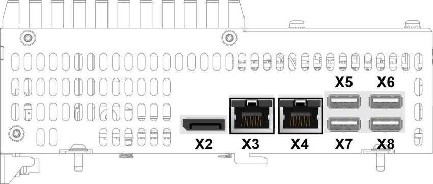
Publisher: SIGMATEK GmbH & Co KG
                                   A-5112 Lamprechtshausen
                                      Tel.: +43/6274/4321
                                    Fax: +43/6274/4321-18
                                   Email: office@sigmatek.at
                               WWW.SIGMATEK-AUTOMATION.COM

                                               Copyright © 2020
                                            SIGMATEK GmbH & Co KG

                                       Translation from German

All rights reserved. No part of this work may be reproduced, edited using an electronic system, duplicated or dis-
tributed in any form (print, photocopy, microfilm or in any other process) without express permission.

We reserve the right to make changes in the content without notice. SIGMATEK GmbH & Co KG is not responsible
for technical or printing errors in this handbook and assumes no responsibility for damages that occur through its
use.
BUILD-IN TOUCH TERMINAL                ETT 2144

Build-in Touch Terminal                                                      ETT 2144
The ETT 2144 is an intelligent panel for visualizing, operating and monitoring automated pro-
cesses.

A capacitive touch screen serves as the input medium for process data and parameters. The
output is shown on a 21.5" TFT color display.

Via the high-performance processor, complex HTML5 applications can be displayed without
problems.

The available interfaces can be used to exchange process data or configure the multi-touch
terminal. An M.2 SSD serves as the storage medium for the operating system, application
and application data.

21.01.2021                                                                           Page 1
ETT 2144           BUILD-IN TOUCH TERMINAL

Contents
1    Introduction ............................................................................. 5
     1.1           Target Group/Purpose of this Operating Manual ...................... 5

     1.2           Important Reference Documentation ......................................... 5

     1.3           Contents of Delivery ..................................................................... 5

2    Basic Safety Guidelines ......................................................... 6
     2.1           Symbols Used ............................................................................... 6

     2.2           Disclaimer ...................................................................................... 8

     2.3           General Safety Guidelines ........................................................... 9

     2.4           Software/Training ....................................................................... 10

3    Norms and Guidelines ...........................................................11
     3.1           Guidelines.................................................................................... 11
           3.1.1        EU Declaration of Conformity ............................................................ 11

4    Technical Data .......................................................................12
     4.1           Performance Data ....................................................................... 12

     4.2           Electrical Requirements ............................................................. 13

     4.3           Display ......................................................................................... 14

     4.4           Control Unit ................................................................................. 14

     4.5           Minimum Distance between Operating Elements for Multi-
                   touch Applications ..................................................................... 15

     4.6           Environmental Conditions ......................................................... 16

     4.7           Miscellaneous ............................................................................. 16

Page 2                                                                                                 21.01.2021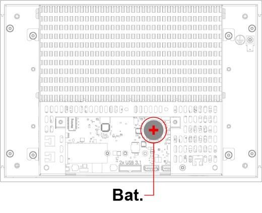
BUILD-IN TOUCH TERMINAL                             ETT 2144

5    Mechanical Dimensions ........................................................ 17

6    Interfaces ............................................................................... 18
      6.1        Connections Bottom................................................................... 18
         6.1.1        X1: Supply (4-pin Phoenix RM 3.5) ................................................... 18

      6.2        Left Side Connectors .................................................................. 19
         6.2.1        X2: DisplayPort Output V1.2a ........................................................... 19

         6.2.2        X3, X4: Ethernet 1, 2 10/100/1000 (RJ45) ........................................ 20

         6.2.3        X5-X8: USB 2.0 (Type A) .................................................................. 20

      6.3        Applicable Connectors ............................................................... 20

7    Display ................................................................................... 21
      7.1        Status LEDs Front....................................................................... 21

8    Transport/Storage ................................................................. 22

9    Assembly/Installation ........................................................... 23
      9.1        Check Contents of Delivery ....................................................... 23

      9.2        Installation ................................................................................... 23

      9.3        Restricted Space Around Rear Trimming ................................ 24

      9.4        Required Cutout for Mounting the Terminal ............................ 25

      9.5        Mounting Position....................................................................... 26

10   Wiring ..................................................................................... 27
      10.1       Ground ......................................................................................... 27

      10.2       Shielding ...................................................................................... 28

      10.3       ESD Protection ............................................................................ 28
21.01.2021                                                                                                Page 3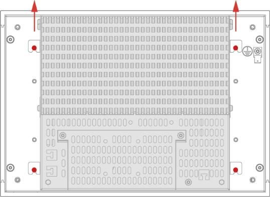
ETT 2144            BUILD-IN TOUCH TERMINAL

     10.4           USB Interface Connections ....................................................... 28

11   Display “Burn-In” Effect ........................................................29

12   Buffer Battery .........................................................................30
     12.1           Exchanging the Battery.............................................................. 31

13   Maintenance ...........................................................................32
     13.1           Cleaning the Touch Screen ....................................................... 32

     13.2           Service ......................................................................................... 33
           13.2.1        Calibrating the Touch Screen ............................................................ 33

     13.3           Repair ........................................................................................... 33

     13.4           Position Series Label Sub Device ............................................. 34

14   Process Diagram ...................................................................35

15   Status and Error Messages...................................................36

16   Modularity...............................................................................43
     16.1           Removing the PIM from the Touch Panel ................................. 44

     16.2           Mounting the PIM onto the Touch Panel .................................. 45

17   Disposal ..................................................................................46

18   Accessories............................................................................47
     18.1           Battery.......................................................................................... 47

Page 4                                                                                                   21.01.2021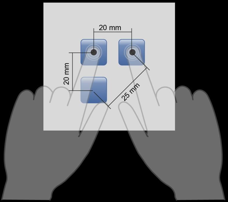
BUILD-IN TOUCH TERMINAL                 ETT 2144

1     Introduction
1.1       Target Group/Purpose of this Operating Manual
This operating manual contains all information required to operate this product.

This operating manual is intended for:

      •    Project planners
      •    Technicians
      •    Commissioning engineers
      •    Machine operators
      •    Maintenance/test technicians

General knowledge of automation technology is required.

Further help and training information, as well as the appropriate accessories can be found on
our website www.sigmatek-automation.com.

Our support team is also happily available to answer your questions.
Please see our website for our hotline number and business hours.

1.2       Important Reference Documentation

      •    PIM 041
      •    TP 2161
      •    HW IP Address Settings

This and additional documents can be downloaded from our website or obtained through
SIGMATEK Support.

1.3       Contents of Delivery
ETT 2144
14x angle bracket
1x 4-pin Phoenix connector plug

21.01.2021                                                                           Page 5
ETT 2144 BUILD-IN TOUCH TERMINAL
2 Basic Safety Guidelines
2.1 Symbols Used
The following symbols are used in the operator documentation for warning and danger mes-
sages, as well as informational notes:
DANGER Danger indicates that death or serious injury will occur, if the specified
measures are not taken.
To avoid death or serious injuries, observe the all guidelines.
Danger indique une situation dangereuse qui, faute de prendre les mesures
adéquates, entraînera des blessures graves, voire mortelles.
Respectez toutes les consignes pour éviter des blessures graves,
voire mortelles
WARNING Warning indicates that death or serious injury can occur, if the specified
measures are not taken.
To avoid death or serious injuries, observe the all guidelines.
Avertissement d’une situation dangereuse qui, faute de prendre les mesures
adéquates, entraînera des blessures graves, voire mortelles.
Respectez toutes les consignes pour éviter des blessures graves,
voire mortelles.
CAUTION Caution indicates that moderate to slight injury can occur, if the specified
measures are not taken.
To avoid moderate to slight injuries, observe the all guidelines.
Attention indique une situation dangereuse qui, faute de prendre les mesures
adéquates, peut entraîner des blessures assez graves ou légères.
Respectez toutes les consignes pour éviter des blessures graves,
voire mortelles.
INFORMATION
Provides important information on the product, handling or relevant sections
of the documentation, which require attention.
Fournit des recommendations importantes sur le produit, la manipulation ou
sections relevantes de la documentation, qui nécessitent prêter une attention
particulière.
Page 6 21.01.2021BUILD-IN TOUCH TERMINAL ETT 2144
Danger for ESD-sensitive components.
Les signes de danger pour les composants sensibles aux décharges
électrostatiques.
21.01.2021 Page 7ETT 2144 BUILD-IN TOUCH TERMINAL
2.2 Disclaimer
The contents of this operating manual were prepared with the greatest care.
However, deviations cannot be ruled out. This operating manual is regularly
checked and required corrections are included in the subsequent versions.
The machine manufacturer is responsible for the proper assembly, as well
as device configuration. The machine operator is responsible for safe han-
dling, as well as proper operation.
The current operating manual can be found on our website. If necessary,
contact our support.
Subject to technical changes, which improve the performance of the devices.
The following operating manual is purely a product description. It does not
guarantee properties under the warranty.
Please thoroughly read the corresponding documentation and this operating
manual before handling a product.
SIGMATEK GmbH & Co KG is not liable for damages caused through
non-compliance with these instructions or applicable regulations.
Page 8 21.01.2021BUILD-IN TOUCH TERMINAL ETT 2144
2.3 General Safety Guidelines
The Safety Guidelines in the other sections of this operating manual must be observed.
These instructions are visually emphasized by symbols.
According to EU Guidelines, the operating instructions are a component of a
product.
This operating manual must therefore be accessible in the vicinity of the ma-
chine since it contains important instructions.
This operating manual should be included in the sale, rental or transfer of the
product, or its online availability indicated.
Maintain this operating manual in readable condition and keep it accessible
for reference.
Regarding the requirements for Safety and health connected to the use of
machines, the manufacturer must perform a risk assessment in accordance
with machine guidelines 2006/42/EG before introducing a machine to the
market.
Before commissioning this product, check that conformance with the provi-
sions of the 2006/42/EG guidelines is correct. As long as the machine with
which the with the product should be used does not comply with the guide-
line, operating this product is prohibited.
Operate the unit with devices and accessories approved by SIGMATEK only.
CAUTION Handle the device with care and do not drop or let fall.
Prevent foreign bodies and fluids from entering the device.
The device must not be opened, otherwise it could be damaged!
The module complies with EN 61131-2.
In combination with a machine, the machine builder must comply with EN
60204-1 standards.
For your own safety and that of others, compliance with the environmental
conditions is essential.
The control cabinet must be connected to ground correctly.
To perform maintenance or repairs, disconnect the system from the power
supply.
21.01.2021 Page 9ETT 2144 BUILD-IN TOUCH TERMINAL 2.4 Software/Training The application is created with the software LASAL CLASS 2 and LASAL SCREEN Editor. Training for the LASAL development environment, with which the product can be configured, is provided. Information on our training schedule can be found on our website. Page 10 21.01.2021
BUILD-IN TOUCH TERMINAL              ETT 2144

3       Norms and Guidelines
3.1      Guidelines
The product was constructed in compliance with the following European Union guidelines
and tested for conformity:

3.1.1     EU Declaration of Conformity

               EU Declaration of Conformity
               The product ETT 2144 conforms to the following European guidelines:
                   •   2014/35/EU Low-voltage guideline
                   •   2014/30/EU “Electromagnetic Compatibility” (EMC guideline)
                   •   2011/65/EU “Restricted use of certain hazardous substances in
                       electrical and electronic equipment” (RoHS Guideline)
               The EU Conformity Declarations are provided on the SIGMATEK website.
               See: Products/downloads or use the search function and keyword “EU Dec-
               laration of Conformity”.

21.01.2021                                                                      Page 11
ETT 2144 BUILD-IN TOUCH TERMINAL
4 Technical Data
4.1 Performance Data
Processor Intel® Celeron® J4005
Processor cores 21)
Processor clock 2.0-2.7 GHz
Internal cache 4 Mbytes
Internal program and data 2-Gbyte DDR4 (SODIMM)
memory (RAM)
Graphics Intel® UHD Graphics 600
Hard drive 32-Gbyte SATA M.2 SSD
Interfaces 4x USB 2.0 (Type A)
1x DisplayPort output V1.2a (max. 1920 x 1200 px at 60 Hz)
2x Ethernet (Gbit)
Internal interfaces 1x Panel Interface Connector
Signal generator no
Display 21.5“ TFT color display
Resolution Full HD 1920 x 1080 pixels
Operating panel touch screen (projective capacitive)
Status LEDs 1x red, 1x green
Real-time clock yes
Cooling passive (fanless)
1)
Attention: When programming (with LASAL) on multicore CPUs, particular focus must be placed on thread security!
Page 12 21.01.2021BUILD-IN TOUCH TERMINAL ETT 2144
4.2 Electrical Requirements
Supply voltage +18-30 V DC (SELV/PELV), typically+24 V DC
UL: Class 2 or LVLC(1)
Current consumption of (+24 V) typically 1500 mA maximum 2000 mA
power supply (without externally connected de- (with external devices connected)
vices)
Inrush current with 24 V/10 A maximum 2.2 A (for 1.8 ms, load-dependent)
fixed voltage supply
Inrush current without current- maximum 3.5 A (for 6 µs, load-dependent)
limiting supply
(1) For USA and Canada:
The supply must be limited to:
a) max. 5 A at voltages from 0-20 V DC, or
b) 100 W at voltages from 20-60 V DC.
The limiting component (e.g. transformer, power supply or fuse) must be certified by an
NRTL (Nationally Recognized Testing Laboratory).
21.01.2021 Page 13ETT 2144 BUILD-IN TOUCH TERMINAL
4.3 Display
Type 21.5” TN color display
Resolution FullHD 1920 x 1080 pixels
Color depth 24-bit RGB
LCD mode normally black1)
LCD Polarizer transmissive2)
Pixel size 0.248 x 0.248 mm
Active surface 476.64 x 268.11
Backlighting LED
Contrast ratio typically 5000:1
Brightness typically 300 cd/m²
Angle CR ≥ 10 left, right, top, bottom typically 89°
Life span by compliance with the ambient conditions, the brightness of the display
sinks after 50,000 operating hours to 50 % of the original brightness
1)
If no display data is available, the display remains black when the backlighting is on.
2)
Display technology, with which display backlighting is used.
Due to the manufacturing process, individual pixel errors cannot be excluded to 100% and therefore do not
constitute a reduction in quality.
4.4 Control Unit
Touch panel projective capacitive touch panel
Cleaning see chapter 13.1.
A projective capacitive touch screen is built into the panel, with which 10-
finger input, Zoom and gesture functions can be implemented. Data can be
input using fingers, a project capacitive touch pen as well as with thin gloves.
The device must always be grounded to ensure stable function of the touch
screen. The touch function may still have to be individually adapted to the
respective environmental conditions.
Page 14 21.01.2021BUILD-IN TOUCH TERMINAL ETT 2144
4.5 Minimum Distance between Operating Elements for Multi-touch Appli-
cations
To guarantee smooth operation with multitouch applications, buttons and control elements
that should be operated at the same time must have the minimum clearance shown below
(depending on the estimated touch point).
The size of the buttons and operating elements directly affect the operability
of the application. Small operating elements should therefore be avoided.
21.01.2021 Page 15ETT 2144 BUILD-IN TOUCH TERMINAL
4.6 Environmental Conditions
Storage temperature -10 ... +70 °C
Environmental temperature 0 ... +50 °C
Humidity 10-95 %, non-condensing
Installation altitude above sea 0-2000 m without derating
level
> 2000 m with derating of the maximum environment temperature by 0.5 °C
per 100 m
Operating conditions pollution degree 2
EMC resistance in accordance with EN 61000-6-2 (industrial area)
EMC noise generation in accordance with EN 61000-6-4 (industrial area)
Vibration resistance EN 60068-2-6 5-200 Hz: amplitude 3.5 mm
Transition frequency: 8.42454 Hz
acceleration: 1 g
duration: 10 cycles
cycle: 1 octave/minute
Shock resistance EN 60068-2-27 15 g (147.15 m/s²)
Protection type EN 60529 front: IP651)
protected through the housing cover IP201)
1)
IP housing protection type was tested for Europe and is not part of a UL-certification for the device
4.7 Miscellaneous
Article number 01-230-2144
Hardware version 1.x
Operating system Salamander
Default IP address
Intel Ethernet (X3) automatic (DHCP)
Realtek Ethernet (X4) automatic (DHCP)
Default browser address 10.10.150.1
Approvals CE;
the ETT 2144 consists of a TP 2161 (CULUS (E247993)) and
a PIM 041 (UL in preparation)
Page 16 21.01.2021BUILD-IN TOUCH TERMINAL ETT 2144
5 Mechanical Dimensions
Dimensions 539 x 331 x 90 mm (W x H x D)
Material front plate: 2.8 mm glass (touch screen) in black anodized aluminum frame
housing: sheet steel
heat sink: anodized aluminum
Weight 6.5 kg
21.01.2021 Page 17ETT 2144 BUILD-IN TOUCH TERMINAL
6 Interfaces
6.1 Connections Bottom
Symbol Image ETT 1544
6.1.1 X1: Supply (4-pin Phoenix RM 3.5)
Pin Function
1 +24 V DC
2 +24 V DC
3 GND
4 GND
Page 18 21.01.2021BUILD-IN TOUCH TERMINAL ETT 2144
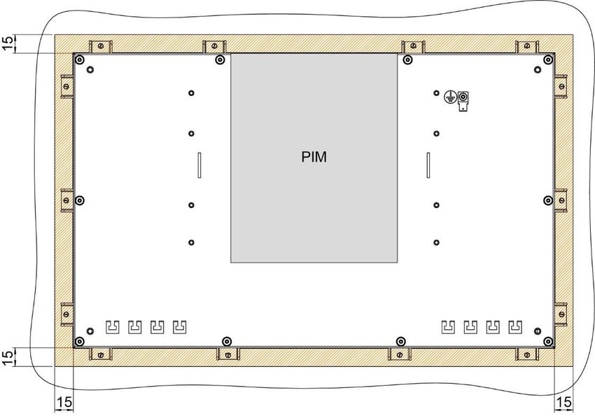
6.2 Left Side Connectors
Symbol Image ETT 1544
6.2.1 X2: DisplayPort Output V1.2a
Pin Function
1 Lane 0 (p)
2 GND
3 Lane 0 (n)
4 Lane 1 (p)
5 GND
6 Lane 1 (n)
7 Lane 2 (p)
8 GND
9 Lane 2 (n)
10 Lane 3 (p)
11 GND
12 Lane 3 (n)
13 Config1
14 Config2
15 AUX CH (p)
16 GND
17 AUX CH (n)
18 Hot Plug
19 Return
20 DP_VCC_3V3
21.01.2021 Page 19ETT 2144 BUILD-IN TOUCH TERMINAL
6.2.2 X3, X4: Ethernet 1, 2 10/100/1000 (RJ45)
Pin Function
1 DA+
2 DA-
3 DB+
4 DC+
5 DC-
6 DB-
7 DD+
8 DD-
6.2.3 X5-X8: USB 2.0 (Type A)
Pin Function
1 +5 V, Iout,max = 500 mA
2 D-
3 D+
4 GND
It should be noted that many of the USB devices on the market do not comply
with USB specifications; this can lead to device malfunctions. It is also pos-
sible that these devices will not be detected at the USB port or function cor-
rectly. Therefore, it is recommended that every USB stick be tested before
actual use.
6.3 Applicable Connectors
X1: 4-pin Phoenix plug with spring terminal FK-MCP 1.5/ 4-ST-3.5 (included with
delivery)
X2: 20-pin DisplayPort connector (not included in delivery)
X3, X4: 8-pin RJ45 (not included in delivery)
X5-X8: USB 4-pin, Type A (downstream connector) (not included with delivery)
Page 20 21.01.2021BUILD-IN TOUCH TERMINAL ETT 2144
7 Display
7.1 Status LEDs Front
LED LED Status Definition
1 green DCOK
2 red not available
21.01.2021 Page 21ETT 2144 BUILD-IN TOUCH TERMINAL
8 Transport/Storage
This device contains sensitive electronics. During transport and storage, high
mechanical stress must therefore be avoided.
For storage and transport, the same values for humidity and vibration as for
operation must be maintained!
During transport, temperature and humidity fluctuations may occur. Ensure
that no moisture condenses within or on the device be letting the device cli-
matize to the room temperature while turned off.
Page 22 21.01.2021BUILD-IN TOUCH TERMINAL ETT 2144
9 Assembly/Installation
9.1 Check Contents of Delivery
Ensure that the contents of the delivery are complete and intact. See chapter 1.3Contents of
Delivery for more information.
On receipt and before initial use, check the device for damage. If the device
is damaged, contact our customer service and do not install the device in
your system.
Damaged components can disrupt or damage the system.
9.2 Installation
The following instructions must be followed when installing the terminal:
• For installation with the screw terminals provided, it is recommended that the installation
panel have a material strength of at least 1 mm and a maximum of 2 mm. The screw-in
brackets can be tightened with a maximum torque of 0.2 Nm. For this purpose, a 3x 0.5
flat-tip screwdriver is required.
• To avoid damage to the aluminum frame, it is important to ensure that during installation,
the contact surface is clean (free of debris, uneven areas). Unevenness can lead to
stress on the glass/aluminum frame or contamination from dust and water.
To dissipate the waste heats from the device, the clearance between the heatsink of the PIM
and the back wall should be at least 45 mm.
The device’s power loss can reach up to 30 Watts. To ensure the necessary air circulation
for cooling, the mounting instructions must be followed!
21.01.2021 Page 23ETT 2144 BUILD-IN TOUCH TERMINAL
9.3 Restricted Space Around Rear Trimming
Symbol Image ETT 1544
A restricted area of 15 mm around the terminal must be ensured. This is required to mount
the terminal onto the machine using the screw terminals provided and when necessary, ex-
change the module without having to remove the entire device.
Page 24 21.01.2021BUILD-IN TOUCH TERMINAL ETT 2144 9.4 Required Cutout for Mounting the Terminal Control cabinet cutout width X 528 mm Control cabinet cutout height Y 320 mm Maximum thickness of control 3 mm cabinet wall Z 21.01.2021 Page 25
ETT 2144         BUILD-IN TOUCH TERMINAL

9.5   Mounting Position
Observe the mounting position of 60-120°.

              The specified installation distances may be reduced if appropriate measures
              and technical precautions are taken to dissipate the corresponding waste
              heat.

Page 26                                                                       21.01.2021
BUILD-IN TOUCH TERMINAL ETT 2144
10 Wiring
10.1 Ground
The device must be grounded to protective earth (PE) via the blade terminal provided. In
addition, ensure that when installing into the control cabinet, a large grounding surface is
provided. It is important to establish a low-Ohm connection to ground to ensure error-free
function. The ground connection must be made with the maximum wire cross-section and
largest (electrical) surface possible. The cable length of the ground connection must also be
kept as short as possible.
Symbol Image ETT 1544
21.01.2021 Page 27ETT 2144 BUILD-IN TOUCH TERMINAL
10.2 Shielding
For Ethernet, CAT5e-compliant cables are recommended. The cable shielding is connected
to ground via the RJ45 connector. Noise signals can then be prevented from reaching the
electronics and affecting the function.
10.3 ESD Protection
Typically, USB devices (keyboard, mouse etc.) are not equipped with
shielded cables. These devices are disrupted by electrostatic discharge and
in some instances, no longer function.
Before any device is connected to- or disconnected from the product, the
potential with ground must be equalized (by touching the control cabinet or
ground terminal). Electrostatic loads (through clothing or shoes) can be
thereby dissipated.
10.4 USB Interface Connections
The product has a USB interface. This interface can be used to connect various USB devices
(keyboard, mouse, storage media, hubs, etc.). Several USB devices can be connected using
a hub, which are then fully functional.
Page 28 21.01.2021BUILD-IN TOUCH TERMINAL ETT 2144
11 Display “Burn-In” Effect
The “Burn-In” effect describes a pattern burned into the display after displaying the same
contents over a longer period of time (e.g. a single screen).
This effect is also described mostly as “image sticking”, “memory effect/sticking” or “ghost
image”. Here, a distinction is made between a temporary and permanent effect. While the
temporary effect fades after the screen has been turned off for some time or when dynamic
content is displayed, damage from the permanent effect is irreversible.
This effect can have the following causes:
• Operation without a screen saver
• The same contents displayed over a longer time period (e.g. a single screen)
• Operation at high ambient temperatures
• Operation above specifications
The effect can be avoided/reduced by the following actions:
• Using a screen saver
• Deactivating the display when not in use (e.g. screen display black)
• Continuously changing screen content (e.g. video)
Deactivating the display backlighting only does not prevent Burn-In!
21.01.2021 Page 29ETT 2144 BUILD-IN TOUCH TERMINAL
12 Buffer Battery
The exchangeable buffer battery ensures that the clock time and customer-defined BIOS
settings are preserved in the absence of a supply voltage. A lithium battery is installed at the
manufacturer.
The battery has enough capacity to preserve data in the absence of a supply voltage for up
to 5 years.
If the battery is empty, all BIOS settings and the clock time are reset to the factory defaults
and existing SRAM data is deleted.
COMPANY DATA
Lithium battery RENATA 3.0 V / 235 mAh
Battery order number: 01-690-055
Use type CR2032 batteries from RENATA only.
Disconnect the device from the supply before changing the battery.
WARNING Danger of fire and explosion!
Slight to serious injuries can occur from incorrect use of the battery.
Do not recharge, disassemble or throw batteries into fire!
Page 30 21.01.2021BUILD-IN TOUCH TERMINAL ETT 2144
12.1 Exchanging the Battery
1. Turn off the device supply.
2. Remove the locking screws in the battery
cover with a TX10 Torx screwdriver.
3. Remove the battery cover.
4. To remove the battery from the holder press
the gold tab of the battery holder away from
the battery.
5. Caution! The battery easily spring out of the
holder, it is recommended that the tab is
fixed in position when pulling it back.
6. Install the new battery with the correct polar-
ity (+ pole facing up). To install, first slide the
battery underneath the plastic hooks and
then with slight force, press down on the
side with the gold tab.
7. Close the battery cover and tighten the lock-
ing screws.
21.01.2021 Page 31ETT 2144 BUILD-IN TOUCH TERMINAL
13 Maintenance
During maintenance as well as servicing, the safety instructions from chapter
2 must be observed.
13.1 Cleaning the Touch Screen
CAUTION Before cleaning the touch screen, the ETT must be turned off in order to
prevent triggering functions or commands unintentionally!
The touch screen can only be cleaned with a soft, damp cloth. To dampen the cloth, we
recommend a mild cleaning solution such as antistatic foam cleaner. To avoid fluids/cleaning
solutions from getting into the housing, the device must not be sprayed directly. To clean, no
erosive cleaning solutions, chemicals, abrasive cleansers or hard objects that can scratch or
damage the touch screen may be used. The use of steam jets or compressed air is prohibited.
WARNING If the device is contaminated with toxic or erosive chemicals, it must be
carefully cleaned as quickly as possible to prevent personal injury and
machine damage!
To ensure the optimal function of the panel, the touch screen should be
cleaned in regular intervals!
Page 32 21.01.2021BUILD-IN TOUCH TERMINAL ETT 2144
13.2 Service
This product was constructed for low-maintenance operation.
13.2.1 Calibrating the Touch Screen
The touch screen is calibrated at the factory. You should therefore only recalibrate the touch
screen when press-point changes are noticed.
This can be achieved via the CLI command or the application, if the application engineer has
provided the option.
calib
13.3 Repair
When sent for repair, the panel should be transported in the original packag-
ing if possible. Otherwise packaging should be selected that sufficiently pro-
tects the product from external mechanical influences, such as cardboard
filled with air cushioning.
In the event of a defect/repair, send the panel with a detailed error description to the address
listed at the beginning of this document.
21.01.2021 Page 33ETT 2144 BUILD-IN TOUCH TERMINAL 13.4 Position Series Label Sub Device Page 34 21.01.2021
BUILD-IN TOUCH TERMINAL   ETT 2144

14 Process Diagram

21.01.2021                                      Page 35
ETT 2144            BUILD-IN TOUCH TERMINAL

15 Status and Error Messages
Status an error messages are displayed in the LASAL CLASS software status test. POINTER
or CHKSUM messages are shown on the screen.

 Number    Message           Definition                                  Cause/solution

    00     RUN RAM           The user program is currently running in    Info
                             RAM.
                             The display is not affected.
    01     RUN ROM           The user program stored in the program      Info
                             memory module was loaded into the
                             RAM and is currently running.
                             The display is not affected.
    02     RUNTIME           The total time for all cyclic objects ex-   Optimize the application's cyclic
                             ceeds the maximum time; the time can        task.
                             be configured using 2 system variables:
                                                                         Use higher capacity CPU.
                             - Runtime: Remaining time                   Configure preset value
                             - SWRuntime: Preset value for runtime
                               counter
    03     POINTER           Incorrect program pointers were de-         Possible Causes:
                             tected before running the user program
                                                                         - The program memory module is
                                                                           missing, not programmed or de-
                                                                           fective.
                                                                         - The program in the user program
                                                                           memory (RAM) is not executable.
                                                                         - The buffer battery has failed.
                                                                         - The user program has overwritten
                                                                           a software error.

                                                                         Solution:
                                                                         - Reprogram the memory module, if
                                                                           the error reoccurs exchange the
                                                                           module.
                                                                         - Exchange the buffering battery
                                                                         - Correct programming error
    04     CHKSUM            An invalid checksum was detected before     Cause/solution: s. POINTER
                             running the user program.

Page 36                                                                                        21.01.2021
BUILD-IN TOUCH TERMINAL ETT 2144
05 WATCHDOG The program was interrupted via the Possible Causes:
watchdog logic.
- User program interrupts blocked
over a longer period of time (STI
command forgotten).
- Programming error in a hardware
interrupt.
- INB, OUTB, INW, OUTW instruc-
tions used incorrectly.
- The processor is defective.
Solution:
- Correct programming error.
- Exchange CPU
06 GENERAL ERROR General error This error occurs only during the de-
velopment of the operating system.
An error has occurred while stopping the
application over the online interface.
07 PROM DEFECT An error has occurred while programming Causes:
the memory module.
- The program memory module is
defective.
- The user program is too large.
- The program memory module is
missing.
Solution:
- Exchange the program memory
module
08 RESET The CPU has received the reset signal Info
and is waiting for further instructions.
The user program is not processed.
09 WD DEFECT The hardware monitoring circuit (watch- Solution:
dog logic) is defective.
- Exchange CPU
After power-up, the CPU checks the
watchdog logic function. If an error occurs
during this test, the CPU deliberately en-
ters an infinite loop from which no further
instructions are accepted.
10 STOP The program was stopped by the pro-
gramming system.
11 PROG BUSY Reserved
12 PROGRAM LENGTH Reserved
13 PROG END A memory module was successfully pro- Info
grammed.
14 PROG MEMO The CPU is currently programming the Info
memory module.
21.01.2021 Page 37ETT 2144 BUILD-IN TOUCH TERMINAL
15 STOP BRKPT The CPU was stopped by a breakpoint in Info
the program.
16 CPU STOP The CPU was stopped by the program- Info
ming software.
17 INT ERROR The CPU has triggered a false interrupt Causes:
and stopped the user program or has en-
countered an unknown instruction while - A nonexistent operating system
running the program. was used.
- Stack error (uneven number of
PUSH and POP instructions).
- The user program was interrupted
by a software error.
Solution:
- Correct programming error.
18 SINGLE STEP The CPU is in single step mode and is Info
waiting for further instructions.
19 READY A module or project has been sent to the Info
CPU and it is ready to run the program.
20 LOAD The program is stopped and the CPU is Info
currently receiving a new module or pro-
ject.
21 INVALID MODULE The CPU has received a module that Solution:
does not belong to the project.
- Recompile and download the en-
tire project
22 MEMORY FULL The operating system memory (heap) is Causes:
too small. No memory could be reserved
while calling an internal function or an in- - Memory is only allocated but not
terface function is called from the applica- released.
tion.
Solution:
- Clear memory
23 NOT LINKED When starting the CPU, a missing mod- Solution:
ule or a module that does not belong to
the project was detected. - Recompile and download the en-
tire project
24 DIV BY 0 A division error has occurred. Possible Causes:
- Division by 0.
- The result of a division does not fit
in the result register.
Solution:
- Correct programming error.
25 DIAS ERROR While accessing a DIAS module, an error Hardware problem
has occurred.
26 WAIT The CPU is busy. Info
Page 38 21.01.2021BUILD-IN TOUCH TERMINAL ETT 2144
27 OP PROG The operating system is currently being Info
reprogrammed.
28 OP INSTALLED The operating system has been rein- Info
stalled.
29 OS TOO LONG The operating system cannot be loaded; Restart, report error to SIGMATEK.
too little memory.
30 NO OPERATING Boot loader message. Restart, report error to SIGMATEK.
SYSTEM
No operating system found in RAM.
31 SEARCH FOR OS The boot loader is searching for the oper- Restart, report error to SIGMATEK.
ating system in RAM.
32 NO DEVICE Reserved
33 UNUSED CODE Reserved
34 MEM ERROR The operating system loaded does not Solution:
match the hardware configuration.
- Use the correct operating system
version
35 MAX IO Reserved
36 MODULE LOAD ERROR The LASAL Module or project cannot be Solution:
loaded.
- Recompile and download the en-
tire project
37 BOOTIMAGE FAIL- A general error has occurred while load- Contact SIGMATEK
URE ing the operating system.
38 APPLMEM ERROR An error has occurred in the application Solution:
memory (user heap).
- Correct allocated memory access
error
39 OFFLINE This error does not occur in the control. This error code is used in the pro-
gramming system to show that there
is no connection to the control.
40 APPL LOAD Reserved
41 APPL SAVE reserved
44 VARAN MANAGER An error number was entered in the Solution:
ERROR VARAN manager and stopped the pro-
gram. - Read LogFile
45 VARAN ERROR A required VARAN client was discon- Solution:
nected or a communication error has oc-
curred. - Read LogFile
- Error Tree
21.01.2021 Page 39ETT 2144 BUILD-IN TOUCH TERMINAL
46 APPL-LOAD-ERROR An error has occurred while loading the Cause:
application.
- Application was deleted.
Solution:
- Reload the application into the
control.
47 APPL-SAVE-ERROR An error has occurred while attempting to
save the application.
50 ACCESS-EXCEP- Read or write access of a restricted Solution:
TION-ERROR memory area. (I.e. writing to the NULL
pointer). - Correct application errors
51 BOUND EXCEEDED An exception error has occurred while ac- Solution:
cessing arrays. The memory area was
overwritten by accessing an invalid ele- - Correct application errors
ment.
52 PRIVILEDGED IN- An unauthorized instruction for the Cause:
STRUCTION current CPU level was given. For
example, setting the segment register. - The application has overwritten
the application program code.
Solution:
- Correct application errors
53 FLOATING POINT An error has occurred during a floating-
ERROR point operation.
60 DIAS-RISC-ERROR Error from the Intelligent DIAS Master. Restart, report error to SIGMATEK.
64 INTERNAL ERROR An internal error has occurred, all appli- Restart, report error to SIGMATEK.
cations are stopped.
65 FILE ERROR An error has occurred during a file opera-
tion.
66 DEBUG ASSERTION Internal error Restart, report error to SIGMATEK.
FAILED
67 REALTIME RUNTIME The total duration of all real-time objects Solution:
exceeds the maximum time; the time can-
not be configured. - Real-time Optimize the
application's real-time task
2 ms for 386 CPUs (RtWork).
1 ms for all other CPUs - Real-time Reduce the clock time
for the real-time task of all objects.
- Correct application errors
- CPU is overloaded in real-time =>
use a higher capacity CPU.
68 BACKGROUND The total time for all background objects Solution:
RUNTIME exceeds the maximum time; the time can
be configured using 2 system variables: - Optimize the application's back-
ground task (background)
-BTRuntime: Remaining time
- Use higher capacity CPU
-SWBTRuntime: Preset value for runtime
counter - Set SWBTRuntime correctly
Page 40 21.01.2021BUILD-IN TOUCH TERMINAL ETT 2144
70 C-DIAS ERROR A connection error with a C-DIAS module Cause:
has occurred.
- The cause of the error is docu-
mented in the log file
Solution:
- This depends on the cause
72 S-DIAS ERROR A connection error with an S-DIAS Possible Causes:
module has occurred.
- Real network does not match the
project
- S-DIAS client is defective
Solution:
- Analyze log file
75 SRAM ERROR An error occurred while initializing, Possible Causes:
reading or writing SRAM data.
- SRAM configured incorrectly
- Battery for powering the internal
program memory is empty
Solution:
- Analyze log file (Event00.log,
Event19.log)
- Check configuration
- Exchange battery for powering
the internal program memory
95 USER DEFINED 0 User-definable code.
96 USER DEFINED 1 User-definable code.
97 USER DEFINED 2 User-definable code.
98 USER DEFINED 3 User-definable code.
99 USER DEFINED 4 User-definable code.
100 C_INIT Initialization start; the configuration is run.
101 C_RUNRAM The LASAL project was successfully
started from RAM.
102 C_RUNROM The LASAL project was successfully
started from ROM.
103 C_RUNTIME
104 C_READY The CPU is ready for operation.
105 C_OK The CPU is ready for operation.
21.01.2021 Page 41ETT 2144 BUILD-IN TOUCH TERMINAL
106 C_UNKNOWN_CID An unknown object from a stand-alone or
embedded object, or an unknown base
class was detected.
107 C_UNKNOWN_CONSTR The operating system class cannot be
created; the operating system is probably
wrong.
108 C_UNKNOWN_OBJECT Indicates an unknown object in an inter-
preter program; more the one DCC080
object.
109 C_UNKNOWN_CHNL The hardware module number is greater
than 60.
110 C_WRONG_CONNECT No connection to the required channels.
111 C_WRONG_ATTR Wrong server attributes.
112 C_SYNTAX_ERROR Non-specific error. Recompile and
download all project sections.
113 C_NO_FILE_OPEN An attempt was made to open an
unknown table.
114 C_OUTOF_NEAR Memory allocation failed
115 C_OUT OF_FAR Memory allocation failed
116 C_INCOMAPTIBLE An object with the same name already
exists but has a different class.
117 C_COMPATIBLE An object with the same name and class
exists but must be updated.
224 LINKING The application is currently linking.
225 LINKING ERROR An error has occurred while linking.
226 LINKING DONE Linking is complete.
230 OP BURN The operating system is currently being
burned into the Flash memory.
231 OP BURN FAIL An error has occurred while burning the
operating system.
232 OP INSTALL The operating system is currently being
installed.
240 USV-WAIT The power supply was disconnected; the
UPS is active.
The system is shutdown.
241 REBOOT The operating system is restarted.
242 LSL SAVE
243 LSL LOAD
Page 42 21.01.2021BUILD-IN TOUCH TERMINAL ETT 2144
252 CONTINUE
253 PRERUN The application is started.
254 PRERESET The application is ended.
255 CONNECTION BREAK
16 Modularity
Through its modular construction, the device is prepared for a simple exchange of compo-
nents. This makes it possible in the future, to adapt the touch panel (TP) or panel interface
module (PIM) to actual system requirements.
The device is not Hot-Plug capable and can be damaged when the supply is
not disconnected before inserting or removing the PIM.
Always disconnect the supply before inserting or removing.
21.01.2021 Page 43ETT 2144 BUILD-IN TOUCH TERMINAL
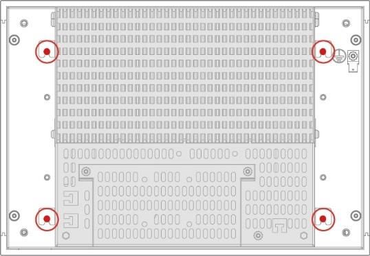
16.1 Removing the PIM from the Touch Panel
This product is a sensitive electronic device. When mounting, as well as dis-
mantling, note that you come into contact with ESD-sensitive areas of the
device.
The applicable ESD measures must be taken!
To remove a PIM from a TP, follow the steps below:
1. Ensure that an ESD-compliant working
method is followed (ESD armband,
ESD clothing).
2. Disconnect the device from the supply.
3. Place the TP flat on its back.
4. Loosen the 4 screws with a TX10
screwdriver
5. Slide the PIM in the direction of the up-
ward as shown.
6. Remove the PIM from the TP.
Page 44 21.01.2021BUILD-IN TOUCH TERMINAL ETT 2144
16.2 Mounting the PIM onto the Touch Panel
To mount the PIM on a TP, follow the steps below:
7. Ensure that an ESD-compliant working
method is followed (ESD armband,
ESD clothing).
8. Disconnect the device from the supply.
9. Place the TP flat on its back.
10. Place the PIM onto the TP so that the
locking clamps of the PIM are securely
held in the notches of the TP.
11. Slide the PIM in the direction of the ar-
rows shown.
12. When locking, a “click” can be clearly
heard and the thin upper section of the
PIM is flush with the housing of the TP.
13. Secure the PIM to the TP using the
four screws provided and a TX-10 Torx
screwdriver
with a torque of 0.7 Nm.
21.01.2021 Page 45ETT 2144 BUILD-IN TOUCH TERMINAL
17 Disposal
Should you need to dispose of the device, the national electronic
scrap regulation must be observed.
The panel cannot be discarded with domestic waste.
Page 46 21.01.2021BUILD-IN TOUCH TERMINAL ETT 2144
18 Accessories
18.1 Battery
Description Order Number
Lithium battery RENATA with 01-690-055
20 mm tab (one-sided)
21.01.2021 Page 47ETT 2144 BUILD-IN TOUCH TERMINAL
Documentation Changes
Change date Affected Chapter Note
page(s)
31.01.2020 Document editing
12.02.2020 10 2.4 Software/Training Chapter added
4.7 Miscellaneous
16 Salamander operating system
14.2.1 Calibrating the Touch
34 Screen CLI command
20.08.2020 35 14.4 Position Series Label Chapter added
Sub Device
27.08.2020 37 15 Process Diagram Chapter added
38 16 Status and Error Messages Chapter added
11.11.2020 13 4.1 Performance Data Footnote cores (programming) added
18 5 Mechanical Dimensions More details
21.01.2021 33 13 Setting the IP Addresses Chapter removed
Page 48 21.01.2021You can also read