EVOSTA2 EVOSTA2d - INSTRUCTIONS FOR INSTALLATION AND MAINTENANCE INSTRUCTIONS POUR L'INSTALLATION ET LA MAINTENANCE INSTRUCCIONES PARA LA ...
←
→
Page content transcription
If your browser does not render page correctly, please read the page content below

INSTRUCTIONS FOR INSTALLATION AND MAINTENANCE
   INSTRUCTIONS POUR L'INSTALLATION ET LA MAINTENANCE
INSTRUCCIONES PARA LA INSTALACIÓN Y EL MANTENIMIENTO

                                  EVOSTA2
                                 EVOSTA2d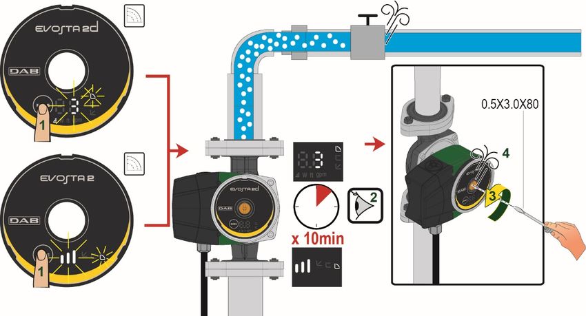
ENGLISH    page   1
FRANÇAIS   page   17
ESPAÑOL    pág    33

ENGLISH

INDEX
1.  KEY ............................................................................................................................................................ 2
2.  GENERAL .................................................................................................................................................. 2
  2.1   Safety.................................................................................................................................................. 2
  2.2   Responsibility .................................................................................................................................... 2
  2.3   Particular warnings ........................................................................................................................... 3
3. PRODUCT DESCRIPTION ........................................................................................................................ 3
4. PUMPED LIQUIDS..................................................................................................................................... 3
5. APPLICATIONS ......................................................................................................................................... 4
6. TECHNICAL DATA .................................................................................................................................... 4
7. MANAGEMENT ......................................................................................................................................... 5
  7.1   Storage ............................................................................................................................................... 5
  7.2   Transport............................................................................................................................................ 5
  7.3   Weight ................................................................................................................................................ 5
8. INSTALLATION ......................................................................................................................................... 5
  8.1   Mechanical installation ..................................................................................................................... 5
  8.2   User Interface Position ..................................................................................................................... 6
  8.3   Rotation of the user interface .......................................................................................................... 7
  8.4   Non-return valve ................................................................................................................................ 8
9. ELECTRICAL CONNECTIONS ................................................................................................................. 9
  9.1   Power supply connection............................................................................................................... 10
10. START ...................................................................................................................................................... 10
  10.1 Degassing the pump ....................................................................................................................... 11
  10.2 Automatic Degassing ..................................................................................................................... 11
11. FUNCTIONS............................................................................................................................................. 12
  11.1 Regulating Modes ........................................................................................................................... 12
    11.1.1 Regulation with Proportional Differential Pressure .................................................................... 12
    11.1.2 Regulation with Constant Differential Pressure ......................................................................... 12
    11.1.3 Regulation with constant curve .................................................................................................. 13
12. CONTROL PANEL................................................................................................................................... 13
  12.1 Elements on the Display................................................................................................................. 13
  12.2 Graphic Display ............................................................................................................................... 14
13. FACTORY SETTINGS ............................................................................................................................. 16
14. TYPES OF ALARM .................................................................................................................................. 16
15. MAINTENANCE ....................................................................................................................................... 16
16. DISPOSAL ............................................................................................................................................... 16
17. DIMENSIONS ........................................................................................................................................... 49
18. PERFORMANCE CURVES .................................................................................................................... .50

INDEX OF FIGURES
Figure 1: Pumped liquids, warnings and operating conditions .......................................................................... 3
Figure 2: Mounting EVOSTA2, EVOSTA2d ...................................................................................................... 5
Figure 3: Assembly position .............................................................................................................................. 6
Figure 4: Positions of the user interface ............................................................................................................ 7
Figure 5: Positions of the user interface ............................................................................................................ 7
Figure 6: Changing the position of the user interface........................................................................................ 8
Figure 7: Venting of the pump ......................................................................................................................... 11
Figure 8: Automatic venting of the pump ......................................................................................................... 11
Figure 9: Display .............................................................................................................................................. 13
Figura 10: EVOSTA2d Display ........................................................................................................................ 14

INDEX OF TABLES
Table 1: Functions ............................................................................................................................................. 3
Table 2: Technical data ..................................................................................................................................... 4
Table 3: Maximum head (Hmax) and maximum flow rate (Qmax) of EVOSTA2, EVOSTA2d circulators ........ 4
Tabella 4: Wiring Evosta2, EVOSTA2d ........................................................................................................... 10
Table 5: Pump operating modes ..................................................................................................................... 15
Table 6: Types of Alarm................................................................................................................................... 16

                                                                               1
ENGLISH

1. KEY
The frontispiece shows the version of this document in the form Vn.x. This version indicates that the document
is valid for all software versions of the device n.y. For example: V3.0 is valid for all Sw: 3.y.

In this document the following symbols will be used to avoid situations of ranger:

                  Situation of general danger. Failure to respect the instructions that follow may cause harm
                  to persons and property.

                  Situation of electric shock hazard. Failure to respect the instructions that follow may cause
                  a situation of grave risk for personal safety.

2. GENERAL

                  Read this documentation carefully before installation.

Skilled personnel: Installation must be carried out by competent, skilled personnel in possession of the
technical qualifications required by the specific legislation in force. The term skilled personnel means persons
whose training, experience and instruction, as well as their knowledge of the respective standards and
requirements for accident prevention and working conditions, have been approved by the person in charge of
plant safety,authorizing them to perform all the necessary activities, during which they are able to recognize
and avoid all dangers. (Definition for technical personnel IEC 364).
The appliance may not be used by children under 8 years old or by persons with reduced physical, sensory or
mental capacities, or who lack experience or knowledge, unless they are under supervision or after they have
received instructions concerning the safe use of the appliance and the understanding of the dangers involved.
Children must not play with the appliance.

                  Ensure that the product has not suffered any damage during transport or storage.
                  Check that the outer casing is unbroken and in excellent conditions.

2.1     Safety

      Use is allowed only if the electric system is in possession of safety precautions in accordance with the
      regulations in force in the country where the product is installed.

2.2     Responsibility

      The Manufacturer does not vouch for correct operation of the machine or answer for any damage that it
      may cause if it has been tampered with, modified and/or run outside the recommended work range or in
      contrast with other indications given in this manual.

                                                     2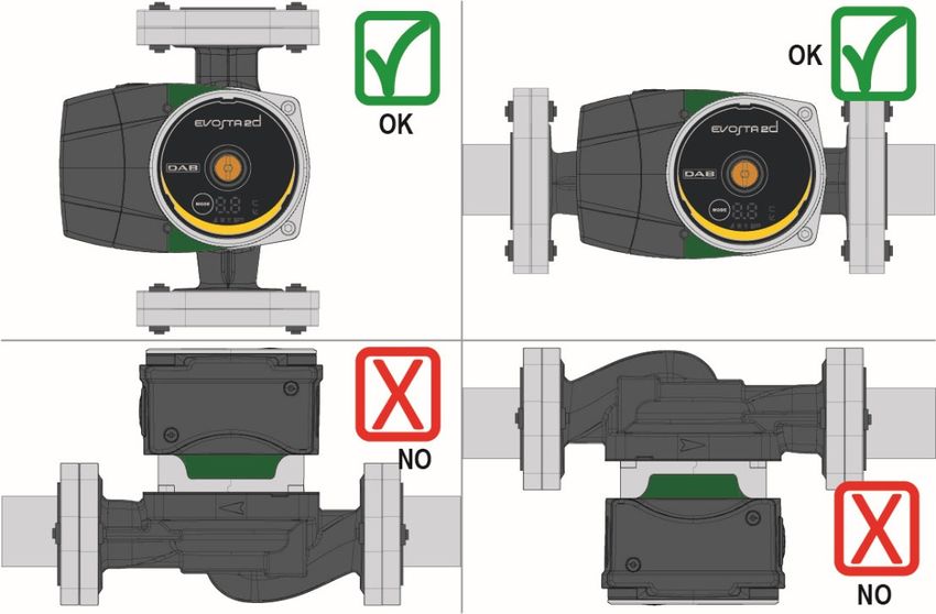
ENGLISH

2.3   Particular warnings

                 Always switch off the mains power supply before working on the electrical or
                 mechanical part of the system. Wait for the warning lights on the control panel to go
                 out before opening the appliance. The capacitor of the direct current intermediate
                 circuit remains charged with dangerously high voltage even after the mains power has
                 been turned off.
                 Only firmly cabled mains connections are admissible. The appliance must be earthed
                 (IEC 536 class 1, NEC and other applicable standards).

                 Mains terminals and motor terminals may still have dangerous voltage when the motor
                 is stopped.

                 If the power cable is damaged, it must be replaced by the technical assistance service
                 or by qualified personnel, so as to avoid any risk.

3. PRODUCT DESCRIPTION

                         Figure 1: Pumped liquids, warnings and operating conditions

The circulators in the EVOSTA2, EVOSTA2d series represent a complete range of circulators.
These installation and operating instructions describe EVOSTA2, EVOSTA2d models. The type of model is
indicated on the pack and on the identification plate.

The table below shows the EVOSTA2, EVOSTA2d models with built-in functions and features.

            Functions/features                              EVOSTA 2               EVOSTA 2d
            Proportional pressure                              ●                       ●
            Constant pressure                                  ●                       ●
            Constant curve                                     ●                       ●
            Dry-running protection                                                     ●
            Automatic degassing                                                        ●
                                              Table 1: Functions

4. PUMPED LIQUIDS
Clean, free from solids and mineral oils, not viscous, chemically neutral, close to the properties of water (max.
glycol contents 30%).
                                                       3
ENGLISH

5. APPLICATIONS
EVOSTA2, EVOSTA2d series circulators allow integrated adjustment of the differential pressure which
enables the circulator performance to be adapted to the actual requirements of the system. This determines
considerable energy saving, a greater possibility of control of the system, and reduced noise.

EVOSTA2, EVOSTA2d circulators are designed for the circulation of:

   –   water in heating and conditioning systems.
   –   water in industrial water circuits.
   –   domestic water only for the versions with stainless steel pump body.

EVOSTA2, EVOSTA2d circulators are self-protected against:

   –   Overloads
   –   Lack of phase
   –   Excess temperature
   –   Over-voltage and under-voltage

6. TECHNICAL DATA
 Supply voltage                                        110-127V (+/-10%), 60 Hz
 Absorbed power                                        See electrical data plate
 Maximum current                                       See electrical data plate
 Grade of protection                                   IPX5
 Protection class                                      F
 TF Class                                              TF 110

 Motor protector                                       No external motor protector is needed

 Maximum environment temperature                       104 ºF / 40°C
 Liquid temperature                                    14 ºF ÷ 230 ºF / -10 ºC ÷ 110 ºC
 Flow rate                                             See Table3
 Head                                                  See Table3
 Maximum working pressure                              1.0 Mpa – 145 psi / 10 bar
 Minimum working pressure                              0.1 Mpa – 14.5 psi / 1 bar
 Lpa [dB(A)]                                           ≤ 43
                                         Table 2: Technical data
Designation index
(example)
                                                          EVOSTA          2         70/        130
        Series name
        2 = without display
        2d = with display
        Maximum head (feet)
        Centre distance (inches)

                    EVOSTA2, EVOSTA2d                 Hmax (ft / m)   Qmax (gpm / m3/h)
                   EVOSTA2 110-127V 60Hz                18 / 5.5          16 / 3.6
                   EVOSTA2d 110-127V 60Hz               18 / 5.5          16 / 3.6
Table 3: Maximum head (Hmax) and maximum flow rate (Qmax) of EVOSTA2, EVOSTA2d circulators

                                                  4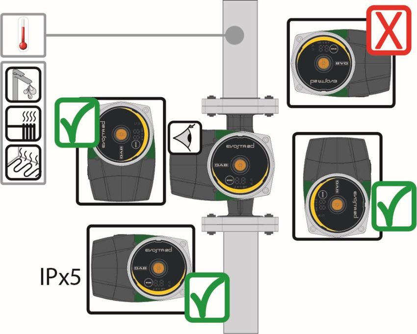
ENGLISH

7. MANAGEMENT
7.1   Storage

All the circulators must be stored in a dry covered place, with possibly constant air humidity, free from vibrations
and dust. They are supplied in their original pack in which they must remain until the time of installation. If this
is not the case, accurately close the suction and delivery mouth.

7.2   Transport

Avoid subjecting the products to needless impacts and collisions. To lift and transport the circulator use lifting
devices with the aid of the pallet supplied with it (if contemplated).

7.3   Weight

The adhesive plate on the packaging indicates the total weight of the circulator.

8. INSTALLATION
                 Always switch off the mains power supply before working on the electrical or
                 mechanical part of the system. Wait for the warning lights on the control panel to go
                 out before opening the appliance. The capacitor of the direct current intermediate
                 circuit remains charged with dangerously high voltage even after the mains power has
                 been turned off.
                 Only firmly cabled mains connections are admissible. The appliance must be earthed
                 (IEC 536 class 1, NEC and other applicable standards).

                 Ensure that the voltage and frequency on the data plate of the EVOSTA2, EVOSTA2d
                 circulator are the same as those of the power mains.

8.1   Mechanical installation

                                                                       C

      A

                                                                     B
                                   Figure 2: Mounting EVOSTA2, EVOSTA2d

The arrows on the pump housing indicate the flow direction through the pump. See fig. 1, pos. A.
1. Fit the two gaskets when you mount the pump in the pipe. See fig. 1, pos. B.
2. Install the pump with a horizontal motor shaft. See fig. 1, pos. C.
3. Tighten the fittings.

                                                       5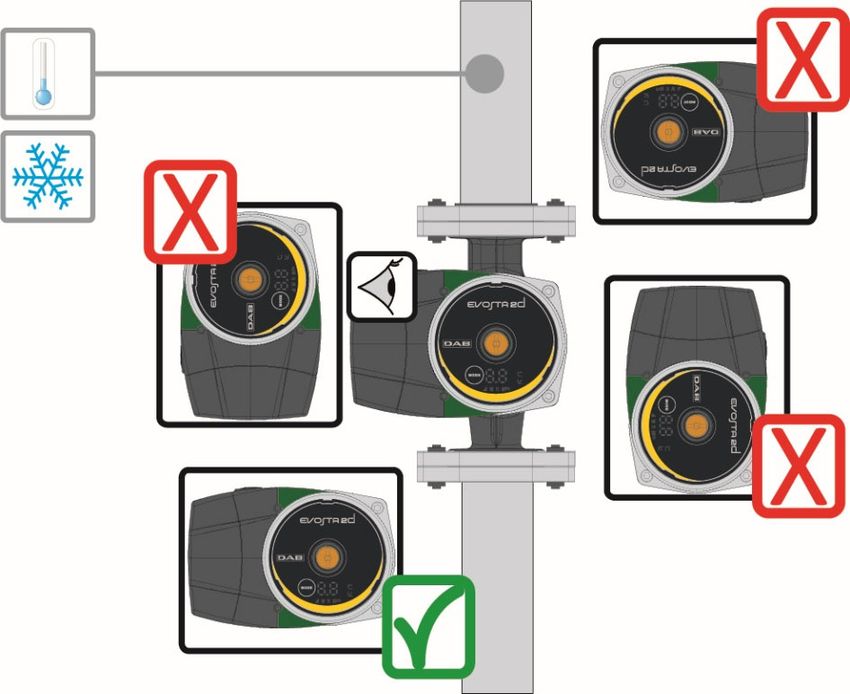
ENGLISH
8.2 User Interface Position
Always install the EVOSTA2, EVOSTA2d circulator with the motor shaft in a horizontal
position.
Install the electronic control device in a vertical position.
Figure 3: Assembly position
The circulator may be installed in heating and conditioning systems on either the delivery pipe or the return
pipe; the arrow marked on the pump body indicates the direction of flow.
Install the circulator as far as possible above the minimum boiler level and as far as possible from bends,
elbows and junction boxes.
To facilitate control and maintenance operations, install an interception valve both on the suction pipe and
on the delivery pipe.
Before installing the circulator, accurately flush the system with only water at 80°C. Then drain the system
completely to eliminate any harmful substance that may have got into circulation.
Avoid mixing additives derived from hydrocarbons and aromatic products with the circulating water. It is
recommended that the addition of antifreeze, where necessary, should not exceed 30%.
In the event of heat insulation use the special kit (if provided) and ensure that the condensate draining
holes in the motor casing are not closed or partly blocked.
In the case of maintenance, always use a set of new gaskets.
Never insulate the electronic control device.
6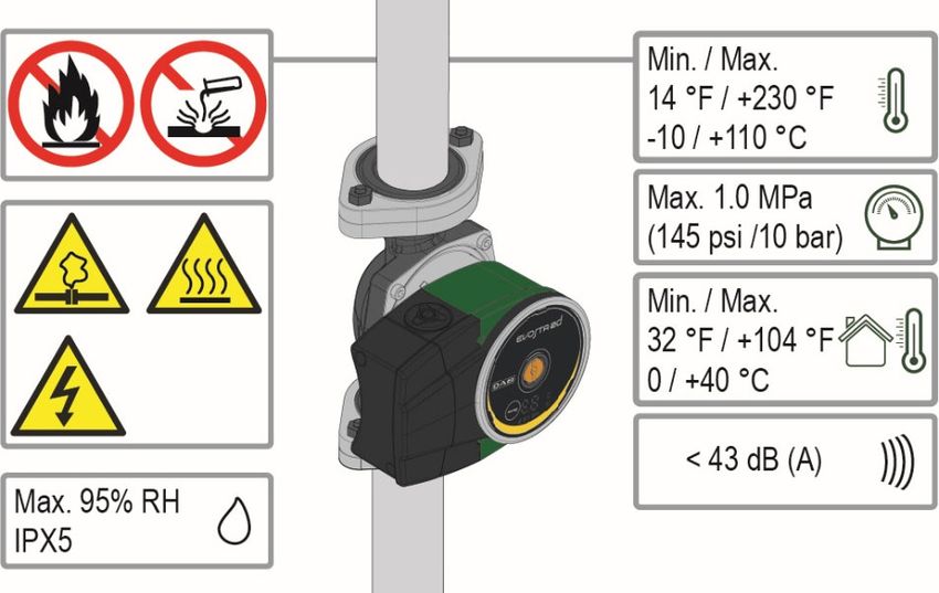
ENGLISH

8.2.1 Positioning of the user interface in heating and domestic hot water systems

It is possible to position the user interface with the cable facing to the left, to the right, or downwards.

                                      Figure 4: Positions of the user interface

8.2.2 Positioning of the user interface in conditioning and cold water systems
The user interface can be positioned only with the cable facing downwards.

                                      Figure 5: Positions of the user interface

8.3    Rotation of the user interface

If the circulator is installed on pipes in a horizontal position, it will be necessary to rotate the interface with the
respective electronic device through 90 degrees in order to maintain the grade of IP protection and to allow
the user a more convenient interaction with the graphic interface.

                                                         7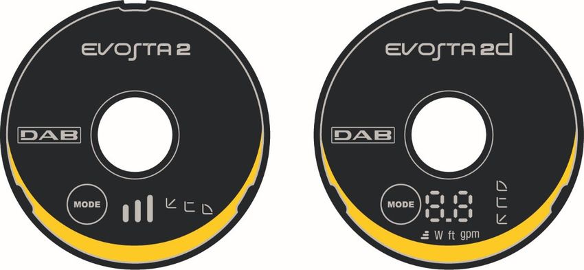
ENGLISH

                 Before rotating the circulator, ensure that it has been completely drained.

To rotate the EVOSTA2, EVOSTA2d circulator, proceed as follows:
    1. Remove the 4 fixing screws of the circulator head.
    2. Rotate the motor casing with the electronic control device through 90 degrees clockwise or
        counterclockwise, as necessary.
    3. Reassemble and tighten the 4 screws that fix the circulator head.

                 The electronic control device must always remain in vertical position!

                             Figure 6: Changing the position of the user interface
                 ATTENTION
                 Water at high temperature.
                 High temperature.

                 ATTENTION
                 System under pressure
                 - Before dismantling the pump, empty the system or close the interception valves on
                 both sides of the pump. The pumped liquid may be at a very high temperature and
                 high pressure.

8.4   Non-return valve

If the system is equipped with a non-return valve, ensure that the minimum pressure of the circulator is always
higher than the valve closing pressure.

                                                     8
ENGLISH
9. ELECTRICAL CONNECTIONS
The electrical connections must be made by expert, qualified personnel.
ATTENTION! ALWAYS RESPECT THE LOCAL SAFETY REGULATIONS.
Always switch off the mains power supply before working on the electrical or
mechanical part of the system. Wait for the warning lights on the control panel to go
out before opening the appliance. The capacitor of the direct current intermediate
circuit remains charged with dangerously high voltage even after the mains power has
been turned off.
Only firmly cabled mains connections are admissible. The appliance must be earthed
(IEC 536 class 1, NEC and other applicable standards).
THE SYSTEM MUST BE CORRECTLY AND SAFELY EARTHED!
It is advised to install a correctly dimensioned differential switch to protect the system,
type: class A with adjustable leakage current, selective.
The automatic differential switch must be marked with the following symbols:
– The circulator does not require any external motor protection.
– Ensure that the supply voltage and frequency are the same as the values indicated on the electrical
data plate of the circulator.
9ENGLISH
9.1 Power supply connection
1 2
Remove the cover
Prepare the wiring up to the terminal box. Connect the cables to the terminal block
Slacken the two fixing screws. cables.
Tabella 4: Wiring Evosta2, EVOSTA2d
10. START
All the starting operations must be performed with the cover of the EVOSTA2,
EVOSTA2d control panel closed.
Start the system only when all the electrical and hydraulic connections have been
completed.
Avoid running the circulator when there is no water in the system.
As well as being at a high temperature and pressure, the fluid in the system may also
be in the form of steam. DANGER OF SCALDING!
It is dangerous to touch the circulator. DANGER OF SCALDING!
Once all the electrical and hydraulic connections have been made, fill the system with water and if necessary
with glycol (for the maximum glycol percentage see par. 4) and feed the system.
Once the system has been started it is possible to modify the operating modes to adapt better to the plant
requirements.
10ENGLISH
10.1 Degassing the pump
Figure 7: Venting of the pump
Always vent the pump before starting!
The pump must never run when dry.
10.2 Automatic Degassing
Automatic degassing occurs only for the Evosta2d pump. Hold down the Mode key for 3 sec and the function
starts: 1 minute at maximum speed, then it passes to the set mode.
Figure 8: Automatic venting of the pump
11ENGLISH
11. FUNCTIONS
11.1 Regulating Modes
EVOSTA2, EVOSTA2d circulators allow the following regulating modes depending on plant requirements:
− Proportional differential pressure regulation depending on the flow present in the plant.
− Constant differential pressure regulation.
− Regulation with constant curve.
The regulating mode may be set through the EVOSTA2, EVOSTA2d control panel.
11.1.1 Regulation with Proportional Differential Pressure
In this regulating mode the differential pressure is
reduced or increased as the demand for water
decreases or increases.
The Hs set point may be set from the display.
Regulation indicated for:
– Heating and conditioning plants with high
load losses
– Plants with secondary differential pressure
regulator
– Primary circuits with high load losses
– Domestic water recirculating systems with
thermostatic valves on the rising columns
11.1.2 Regulation with Constant Differential Pressure
In this regulating mode the differential pressure is
kept constant, irrespective of the demand for water,
The Hs set point may be set from the display.
Regulation indicated for:
– Heating and conditioning plants with low
load losses
– Single-pipe systems with thermostatic
valves
– Plants with natural circulation
– Primary circuits with low load losses
– Domestic water recirculating systems with
thermostatic valves on the rising columns
12ENGLISH
11.1.3 Regulation with constant curve
In this regulating mode the circulator works on
characteristic curves at a constant speed.
Regulation indicated for heating and conditioning
plants with constant flow.
12. CONTROL PANEL
The functions of EVOSTA2, EVOSTA2d circulators can be modified by means of the control panel on the cover
of the electronic control device.
12.1 Elements on the Display
3 4
1 Figure 9: Display 2
1 Luminous segments indicating the type of set curve
2 Display showing the instantaneous power absorption in Watt, the flow rate in m3/h, the head in metres
and the set curve.
3 Key for selecting the pump setting
4 Luminous segments indicating the set curve
13ENGLISH
12.2 Graphic Display
12.2.1 Luminous segments indicating the pump setting
The pump presents nine setting options that can be selected with the key.
The pump settings are indicated by six luminous segments on the display.
12.2.2 Key for selecting the pump setting
Whenever the key is pressed, the pump setting is changed. A cycle consists of pressing the key ten
times.
12.2.3 Display Operation
Figura 10: EVOSTA2d Display
The Evosta3 circulator has a display that is able to show the following values.
Height of the selected curve (1-2-3)
Instantaneous power absorption in Watt
Instantaneous head in feet
Instantaneous flow rate in gallon/minut
The values are shown in sequence for 3sec. Once the viewing cycle is ended, the display switches off and
only the operating mode LED remains lit.
If the selection key is pressed within 10sec, the display performs 6 viewing cycles, then goes into stand-by.
If the key is pressed again within 10sec, the display performs 11 more viewing cycles to allow a greater reading
time.
14ENGLISH
12.2.4 Settings of the pump operating mode
EVOSTA2d EVOSTA2
1 Lower curve with proportional pressure, PP1
2 Intermediate curve with proportional pressure, PP2
3 Higher curve with proportional pressure, PP3
4 Lower curve with constant pressure, CP1
5 Intermediate curve with constant pressure, CP2
6 Higher curve with constant pressure, CP3
7 Lower constant curve, I
8 Intermediate constant curve, II
9 Higher constant curve, III
Table 5: Pump operating modes
15ENGLISH
13. FACTORY SETTINGS
Regulating mode: = Minimum proportional differential pressure regulation
14. TYPES OF ALARM
Alarm Description
No. of curve height blinks EVOSTA2
TRIP: loss of motor control, may be caused by incorrect parameters,
2 Blinks
blocked rotor, disconnected phase, disconnected motor
3 Blinks SHORT CIRCUIT: short circuit on phases or between phase and earth
4 Blinks OVERRUN: software fault
SAFETY: safety module error, may be caused by a sudden overcurrent or
5 Blinks
other hardware faults of the board
Alarm Code EVOSTA2d
E1 DRY RUN
TRIP: loss of motor control, may be caused by incorrect parameters,
E2
blocked rotor, disconnected phase, disconnected motor
E3 SHORT CIRCUIT: short circuit on phases or between phase and earth
E4 OVERRUN: software fault
SAFETY: safety module error, may be caused by a sudden overcurrent or
E5
other hardware faults of the board
Table 6: Types of Alarm
15. MAINTENANCE
Cleaning and maintenance activities must not be carried out by children (under 8 years of
age) without supervision by a qualified adult. Before starting any work on the system, before
starting to look for faults it is necessary to disconnect the power supply to the pump (take
the plug out of the socket) and read the use and maintenance instructions.
16. DISPOSAL
This product or its parts must be disposed of in an environment-friendly manner and in
compliance with the local regulations concerning the environment; use public or private local
waste collection systems.
16FRANÇAIS
INDEX
1. LÉGENDE ................................................................................................................................................ 18
2. GÉNÉRALITÉS ........................................................................................................................................ 18
2.1 Sécurité ............................................................................................................................................ 18
2.2 Responsabilités ............................................................................................................................... 18
2.3 Recommandations particulières.................................................................................................... 19
3. DESCRIPTION DU PRODUIT ................................................................................................................. 19
4. LIQUIDES POMPÉS ................................................................................................................................ 19
5. APPLICATIONS ....................................................................................................................................... 20
6. DONNÉES TECHNIQUES ....................................................................................................................... 20
7. GESTION ................................................................................................................................................. 21
7.1 Stockage .......................................................................................................................................... 21
7.2 Transport.......................................................................................................................................... 21
7.3 Poids................................................................................................................................................. 21
8. INSTALLATION ....................................................................................................................................... 21
8.1 Installation mécanique ................................................................................................................... 21
8.2 Positions Interface Utilisateur ....................................................................................................... 22
8.3 Rotation de l'interface utilisateur .................................................................................................. 23
8.4 Clapet antiretour ............................................................................................................................. 24
9. CONNEXIONS ÉLECTRIQUES............................................................................................................... 25
9.1 Connexion ligne d’alimentation ..................................................................................................... 26
10. DÉMARRAGE .......................................................................................................................................... 26
10.1 Dégazage de la pompe ................................................................................................................... 27
10.2 Dégazage automatique ................................................................................................................... 27
11. FONCTIONS ............................................................................................................................................ 28
11.1 Modes de régulation ....................................................................................................................... 28
11.1.1 Régulation à pression différentielle proportionnelle ................................................................... 28
11.1.2 Régulation à pression différentielle constante ........................................................................... 28
11.1.3 Régulation à courbe constante .................................................................................................. 29
12. PANNEAU DE COMMANDE ................................................................................................................... 29
12.1 Éléments sur l'Afficheur ................................................................................................................. 29
12.2 Afficheur Graphique ....................................................................................................................... 30
13. RÉGLAGES D'USINES ........................................................................................................................... 32
14. TYPES D'ALARME .................................................................................................................................. 32
15. ENTRETIEN ............................................................................................................................................. 32
16. MISE AU REBUT ..................................................................................................................................... 32
17. DIMENSIONS ........................................................................................................................................... 49
18. PERFORMANCES COURBES ................................................................................................................ 50
INDEX DES FIGURES
Image 1: Liquides pompés, avertissements et conditions de fonctionnement ................................................ 19
Image 2: Montage de EVOSTA2, EVOSTA2d ................................................................................................ 21
Image 3: Position de montage ......................................................................................................................... 22
Image 4: Positions de l'interface utilisateur ..................................................................................................... 23
Image 5: Positions de l'interface utilisateur ..................................................................................................... 23
Image 6: Changement de position de l'interface utilisateur............................................................................. 24
Image 7: Purge de la pompe ........................................................................................................................... 27
Image 8: Purge automatique de la pompe ...................................................................................................... 27
Image 9: Afficheur............................................................................................................................................ 29
Image 10: Afficheur Evosta2d ......................................................................................................................... 30
INDEX DES TABLEAUX
Tableau 1: Fonctions et fonctionnement ......................................................................................................... 19
Tableau 2: Données techniques ...................................................................................................................... 20
Tableau 3: Hauteur d’élévation maximum (Hmax) et débit maximum (Qmax) des circulateurs EVOSTA2,
EVOSTA2d ............................................................................................................................................... 20
Tableau 4: Montage du connecteur Evosta2, Evosta2d.................................................................................. 26
Tableau 5: Modes de fonctionnement des pompes ........................................................................................ 31
Tableau 6: Types D'Alarme ............................................................................................................................. 32
17FRANÇAIS
1. LÉGENDE
Le frontispice indique la version du présent document dans la forme Vn.x. Cette version indique que le
document est valable pour toutes les versions logicielles du dispositif n.y. Ex. : V3.0 est valable pour toutes
les versions logicielles : 3.y.
Dans le présent document nous utiliserons les symboles suivants pour indiquer les situations de danger :
Situation de danger générique. Le non-respect des prescriptions qui accompagnent ce
symbole peut provoquer des dommages aux personnes et aux biens.
Situation de danger de décharge électrique. Le non-respect des prescriptions qui
accompagnent ce symbole peut provoquer une situation de risque grave pour la sécurité
des personnes.
2. GÉNÉRALITÉS
Avant de procéder à l’installation lire attentivement cette documentation.
L’installation doit être exécutée par du personnel compétent et qualifié, possédant les caractéristiques requises
par les normes spécifiques en la matière.Le terme personnel qualifié entend des personnes qui, par leur
formation, leur expérience et leur instruction, ainsi que par leur connaissance des normes, prescriptions et
dispositions traitant de la prévention des accidents et des conditions de service, ont été autorisées par le
responsable de la sécurité de l’installation à effectuer toutes les activités nécessaires et sont donc en mesure
de connaître et d’éviter tout danger. (Définition du personnel technique CEI 364
L’appareil ne peut pas être utilisé par des enfants âgés de moins de 8 ans et par des personnes avec
capacités physiques, sensorielles ou mentales réduites, ou dépourvues d’expérience ou de la connaissance
nécessaire à moins de le faire sous surveillance ou bien après que ces personnes ont reçu les instructions
concernant l’utilisation sûre de l’appareil et ont compris les risques encourus. Les enfants ne doivent pas jouer
avec l’appareil.
Vérifier que le produit n’a pas subi de dommages dus au transport ou au stockage.
Contrôler que l’enveloppe est intacte et en excellentes conditions.
2.1 Sécurité
L’utilisation est autorisée seulement si l’installation électrique possède les caractéristiques de sécurité
requises par les normes en vigueur dans le pays d’installation du produit.
2.2 Responsabilités
Le constructeur décline toute responsabilité en cas de mauvais fonctionnement de la machine ou en cas
d’éventuels dommages provoqués par cette dernière si elle a été manipulée et modifiée ou bien, si on l’a
fait fonctionner au-delà des valeurs de fonctionnement conseillées ou en contraste avec d’autres
dispositions contenues dans ce manuel.
18FRANÇAIS
2.3 Recommandations particulières
Avant d’intervenir sur la partie électrique ou mécanique de l’installation couper
toujours la tension de secteur. Attendre l’extinction des voyants sur le panneau de
commande avant d’ouvrir l’appareil. Le condensateur du circuit intermédiaire en
courant continu reste sous tension à une valeur particulièrement élevée même après
le débranchement de l’appareil.
Seuls les branchements de secteur solidement câblés sont admissibles. L’appareil
doit être mis à la terre (CEI 536 classe 1, NEC et autres normes concernant cette
disposition).
Les bornes de secteur et les bornes moteur peuvent porter une tension dangereuse
même quand le moteur est arrêté.
Si le câble d’alimentation est abîmé, il doit être remplacé par le service après-vente
ou par du personnel qualifié, de manière à prévenir n’importe quel risque.
3. DESCRIPTION DU PRODUIT
Image 1: Liquides pompés, avertissements et conditions de fonctionnement
Les circulateurs de la série EVOSTA2, EVOSTA2d constituent une gamme complète de circulateurs.
Ce manuel d'installation et de fonctionnement décrit les modèles EVOSTA2, EVOSTA2d. Le type de modèle
est indiqué sur l'emballage et sur la plaquette d'identification.
Le tableau ci-dessous présente les différents modèles EVOSTA2, EVOSTA2d ainsi que leurs fonctions
intégrées.
Fonctions EVOSTA 2 EVOSTA 2d
Pression proportionnelle ● ●
Pression constante ● ●
Courbe constante ● ●
Protection contre la marche à sec ●
Dégazage automatique ●
Tableau 1: Fonctions et fonctionnement
4. LIQUIDES POMPÉS
Propre, exempt de substances solides et d'huiles minérales, non visqueux, chimiquement neutre, avec des
caractéristiques proches à celles de l'eau (glycol max. 30%).
19FRANÇAIS
5. APPLICATIONS
Les circulateurs de la série EVOSTA2, EVOSTA2d permettent un réglage intégré de la pression différentielle
qui permet d’adapter les performances du circulateur aux demandes effectives de l’installation. Cela entraîne
des économies d’énergie considérables, une plus grande possibilité de contrôler l’installation et la réduction
du niveau sonore.
Les circulateurs EVOSTA2, EVOSTA2d sont conçus pour la circulation de:
– eau dans les installations de chauffage et de climatisation.
– eau dans les circuits hydrauliques industriels.
– eau sanitaire uniquement pour les versions avec corps de pompe en bronze.
Les circulateurs EVOSTA2, EVOSTA2d sont autoprotégés contre:
– Surcharges
– Manque de phase
– Surchauffe
– Surtension et sous-tension
6. DONNÉES TECHNIQUES
Tension d’alimentation 110-127V (+/-10%), 60 Hz
Puissance absorbée Voir plaquette des données électriques
Courant maximum Voir plaquette des données électriques
Indice de protection IPX5
Classe de protection F
Classe TF TF 110
Aucune protection moteur extérieure n’est
Protection moteur
nécessaire
Température ambiante maximum 104 ºF / 40°C
Température liquide 14 ºF ÷ 230 ºF / -10 ºC ÷ 110 ºC
Débit Voir Tableau 3
Hauteur d’élévation Voir Tableau 3
Pression de service maximum 1.0 Mpa – 145 psi / 10 bar
Pression de service minimum 0.1 Mpa – 14.5 psi / 1 bar
Lpa [dB(A)] ≤ 43
Tableau 2: Données techniques
Index de désignation
(exemple)
EVOSTA 2 70/ 130
Nom de la série
2 = sans afficheur
2d = avec afficheur
Hauteur d’élévation maximale (marche)
Entraxe (pouce)
EVOSTA2, EVOSTA2d Hmax (ft / m) Qmax (gpm / m3/h)
EVOSTA2 110-127V 60Hz 18 / 5.5 16 / 3.6
EVOSTA2D 110-127V 60Hz 18 / 5.5 16 / 3.6
Tableau 3: Hauteur d’élévation maximum (Hmax) et débit maximum (Qmax) des circulateurs EVOSTA2,
EVOSTA2d
20FRANÇAIS
7. GESTION
7.1 Stockage
Tous les circulateurs doivent être stockés dans un endroit couvert, sec et avec une humidité de l’air si possible
constante, exempt de vibrations et de poussières. Ils sont fournis dans leur emballage d’origine dans lequel
ils doivent rester jusqu’au moment de l’installation. Si ce n’est pas le cas, veiller à boucher soigneusement
l’orifice d’aspiration et de refoulement.
7.2 Transport
Éviter de soumettre les produits à des chocs et collisions inutiles. Pour soulever et transporter le circulateur,
se servir d’engins de levage en utilisant la palette fournie de série (si elle est prévue).
7.3 Poids
L’étiquette autocollante située sur l’emballage donne l’indication du poids total du circulateur.
8. INSTALLATION
Avant d’intervenir sur la partie électrique ou mécanique de l’installation couper
toujours la tension de secteur. Attendre l’extinction des voyants sur le panneau de
commande avant d’ouvrir l’appareil. Le condensateur du circuit intermédiaire en
courant continu reste sous tension à une valeur particulièrement élevée même après
le débranchement de l’appareil.
Seuls les branchements de secteur solidement câblés sont admissibles. L’appareil
doit être mis à la terre (CEI 536 classe 1, NEC et autres normes concernant cette
disposition).
S'assurer que les valeurs nominales de tension et fréquence du circulateur EVOSTA2,
EVOSTA2d correspondent bien à celles du secteur.
8.1 Installation mécanique
C
A
B
Image 2: Montage de EVOSTA2, EVOSTA2d
Les flèches sur le corps du circulateur indiquent le sens d'écoulement dans le circulateur. Voir fig. 1, pos. A.
1. Mettre les deux joints en place pendant le montage du circulateur sur la tuyauterie. Voir fig. 1, pos. B.
2. Installer le circulateur avec l'arbre du moteur horizontal. Voir fig. 1, pos. C.
3. Serrer les raccords.
21FRANÇAIS
8.2 Positions Interface Utilisateur
Monter le circulateur EVOSTA2, EVOSTA2d toujours avec l’arbre moteur en position
horizontale. Monter le dispositif de contrôle électronique en position verticale
Image 3: Position de montage
Le circulateur peut être installé dans les installations de chauffage et de climatisation aussi bien sur le
tuyau de refoulement que sur celui d’aspiration ; la flèche estampée sur le corps de pompe indique le sens
du flux.
Dans la mesure du possible, installer le circulateur au-dessus du niveau minimum de la chaudière, le plus
loin possible de courbes, coudes et dérivations.
Pour faciliter les opérations de contrôle et de maintenance, installer un robinet d’arrêt tant sur le tuyau
d’aspiration que sur celui de refoulement.
Avant d’installer le circulateur, effectuer un lavage approfondi de l’installation en utilisant uniquement de
l’eau à 80 °C. Purger complètement l’installation pour éliminer toute substance nocive pouvant entrer en
circulation.
Éviter de mêler à l’eau en circulation des additifs dérivant d’hydrocarbures et des produits aromatiques.
L’ajout d’antigel, quand il est nécessaire, est conseillé dans la proportion maximum de 30 %.
En cas de calorifugeage (isolement thermique), utiliser le kit spécifique (s’il est inclus dans la fourniture)
et vérifier que les orifices de drainage du condensat de la caisse moteur ne sont pas fermés ou
partiellement bouchés.
À chaque intervention de maintenance, remplacer les garnitures par des neuves.
Ne jamais isoler le dispositif de contrôle électronique.
22FRANÇAIS
8.2.1 Positionnement de l'interface utilisateur dans les installations de chauffage et d'eau chaude
sanitaire
Vous pouvez positionner l'interface utilisateur avec le câble orienté vers la gauche, la droite et en bas.
Image 4: Positions de l'interface utilisateur
8.2.2 Positionnement de l'interface utilisateur dans les installations de climatisation et d'eau froide
Vous pouvez positionner l'interface utilisateur uniquement avec le câble orienté vers le bas.
Image 5: Positions de l'interface utilisateur
8.3 Rotation de l'interface utilisateur
Si l'installation est réalisée sur des tuyaux placés horizontalement, il sera nécessaire de faire pivoter l'interface
de 90 degrés avec le dispositif électronique correspondant afin de maintenir le degré de protection IP et de
permettre à l'utilisateur d'interagir avec l'interface graphique la plus confortable.
23FRANÇAIS
Avant de procéder à la rotation du circulateur, s’assurer que le circulateur a été
complètement vidé.
Pour tourner le circulateur EVOSTA2, EVOSTA2d procéder comme suit :
1. Éliminer les 4 vis de fixation de la tête du circulateur.
2. Tourner de 90 degrés la caisse moteur avec le dispositif de contrôle électronique dans le sens des
aiguilles d’une montre ou dans le sens contraire suivant les besoins.
3. Remonter et visser les 4 vis qui fixent la tête du circulateur.
Le dispositif de contrôle électronique doit toujours rester en position verticale !
Image 6: Changement de position de l'interface utilisateur
ATTENTION
Eau à haute température.
Température élevée.
ATTENTION
Installation pressurisée
- Avant de démonter la pompe, vidanger l'installation ou fermer les vannes d'arrêt des
deux côtés de la pompe. Le liquide pompé peut être à une température très élevée et
à une haute pression.
8.4 Clapet antiretour
Si l’installation est équipée d’un clapet antiretour, contrôler que la pression minimum du circulateur est toujours
supérieure à la pression de fermeture du clapet.
24FRANÇAIS
9. CONNEXIONS ÉLECTRIQUES
Les connexions électriques doivent être effectuées par du personnel expert et qualifié.
ATTENTION ! RESPECTER TOUJOURS LES NORMES DE SÉCURITÉ LOCALES !
Avant d’intervenir sur la partie électrique ou mécanique de l’installation couper
toujours la tension de secteur. Attendre l’extinction des voyants sur le panneau de
commande avant d’ouvrir l’appareil. Le condensateur du circuit intermédiaire en
courant continu reste sous tension à une valeur particulièrement élevée même après
le débranchement de l’appareil.
Seuls les branchements de secteur solidement câblés sont admissibles. L’appareil doit être
mis à la terre (CEI 536 classe 1, NEC et autres normes concernant cette disposition).
ATTENTION ! EFFECTUER UNE MISE À LA TERRE CORRECTE ET SÛRE DE
L’INSTALLATION !
Il est recommandé d'installer un disjoncteur différentiel correctement dimensionné
pour protéger l'installation, de type: classe A, avec courant de fuite réglable, sélectif.
Le disjoncteur différentiel automatique doit être marqué avec les symboles suivants:
– Le circulateur ne nécessite aucune protection externe du moteur
– Contrôler que la tension et la fréquence d’alimentation correspondent aux valeurs indiquées sur la
plaquette d’identification du circulateur.
25FRANÇAIS
9.1 Connexion ligne d’alimentation
2
1
Préparez le câblage jusqu'à la boîte à Enlever le couvercle
bornes. Desserrer les deux vis de fermeture Connecter les câbles des fils du bornier
Tableau 4: Montage du connecteur Evosta2, Evosta2d
10. DÉMARRAGE
Toutes les opérations de démarrage doivent être effectuées avec le couvercle du
panneau de contrôle EVOSTA2, EVOSTA2d fermé !
Ne mettre le système en marche que lorsque toutes les connexions électriques et
hydrauliques ont été complétées.
Éviter de faire fonctionner le circulateur en l’absence d’eau dans l’installation.
Le fluide contenu dans l’installation en plus de la haute température et de pression
peut se trouver sous forme de vapeur. DANGER DE BRÛLURES !
Il est de dangereux de toucher le circulateur. DANGER DE BRÛLURES !
Une fois que toutes les connexions électriques et hydrauliques ont été effectuées remplir l’installation avec de
l’eau additionnée éventuellement de glycol (pour le pourcentage maximum de glycol voir par. 4) et alimenter
le système.
Une fois que le système a démarré, il est possible de modifier les modes de fonctionnement pour mieux
s’adapter aux exigences de l’installation.
26FRANÇAIS
10.1 Dégazage de la pompe
Image 7: Purge de la pompe
Évacuez toujours la pompe avant la mise en service!
La pompe ne doit pas fonctionner à sec.
10.2 Dégazage automatique
Le dégazage automatique n'a lieu que pour la pompe Evosta2d. Appuyer sur la touche Mode pendant 3sec
et la fonction entre en action: 1 minute à la vitesse maximale, puis elle revient au mode réglé.
Image 8: Purge automatique de la pompe
27FRANÇAIS
11. FONCTIONS
11.1 Modes de régulation
Les circulateurs EVOSTA2, EVOSTA2d permettent d’effectuer les modes de régulation ci-après, suivant les
besoins de l’installation:
− Régulation à pression différentielle proportionnelle en fonction du débit présent dans l’installation.
− Régulation à pression différentielle constante.
− Régulation à courbe constante.
Le mode de régulation peut être sélectionné à travers le panneau de commande EVOSTA2, EVOSTA2d.
11.1.1 Régulation à pression différentielle proportionnelle
Avec ce mode de régulation, la pression
différentielle est réduite ou augmentée suivant la
diminution ou l’augmentation de la demande d’eau.
Le point de consigne Hs peut être sélectionné à
travers l’afficheur.
Régulation indiquée pour:
– Installations de chauffage et climatisation
avec pertes de charge élevées
– Installations avec régulateur de pression
différentielle secondaire
– Circuits primaires avec pertes de charge
élevées
– Systèmes de circulation d’eau sanitaires
avec vannes thermostatiques sur les
colonnes montantes
11.1.2 Régulation à pression différentielle constante
Avec ce mode de régulation, la pression
différentielle est maintenue constante,
indépendamment de la demande d’eau.
Le point de consigne Hs peut être sélectionné à
travers l’afficheur.
Régulation indiquée pour:
– Installations de chauffage et climatisation
avec faibles pertes de charge
– Systèmes à un tuyau avec vannes
thermostatiques
– Installations à circulation naturelle
– Circuits primaires avec faibles pertes de
charge
– Systèmes de circulation d’eau sanitaires
avec vannes thermostatiques sur les
colonnes montantes
28FRANÇAIS
11.1.3 Régulation à courbe constante
Avec ce mode de régulation, le circulateur travaille
sur des courbes caractéristiques à vitesse
constante.
Régulation indiquée pour les installations de
chauffage et de climatisation à débit constant.
12. PANNEAU DE COMMANDE
Les fonctions des circulateurs EVOSTA2, EVOSTA2d peuvent être modifiées à l’aide du panneau de
commande situé sur le couvercle du dispositif de contrôle électronique.
12.1 Éléments sur l'Afficheur
3 4
1 Image 9: Afficheur 2
1 Segments lumineux indiquant le type de courbe configurée
2 Afficheur affichant l'absorption instantanée de puissance en watts, le débit en m3/h, la hauteur
d'élévation en mètres et la courbe configurée.
3 Touche de sélection du réglage de la pompe
4 Segments lumineux indiquant la courbe configurée
29You can also read