POWER AND CONTROLS CONTROL
←
→
Page content transcription
If your browser does not render page correctly, please read the page content below
POWER AND CONTROLS
           CONTROL

EN   Dometic Interact - Triple-E 2020 Unity Rear Lounge
     Operation Manual . . . . . . . . . . . . . . . . . . . . . . . . . . . . . . . . . . . . 2

FR   Dometic Interact - Triple-E 2020 Unity Rear Lounge
     Manuel d’utilisation . . . . . . . . . . . . . . . . . . . . . . . . . . . . . . . . . . 26

                                Form No. 3317348.001 8/2020 | ©2020 Dometic Corporation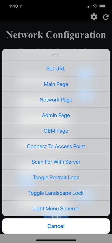
Contents                                                                                                                                Dometic Interact

Service Center & Dealer Locations
Visit: www.dometic.com
Read these instructions carefully. These instructions MUST stay with this product.

Contents
1 Explanation of Symbols and                                                         4.2 Mobile Application Navigation and Use. . . . . .21
  Safety Instructions . . . . . . . . . . . . . . . . . . . . . . . .3                      4.2.1 Prerequisites . . . . . . . . . . . . . . . . . . . . .21
    1.1 Recognize Safety Information . . . . . . . . . . . . . . .3                         4.2.2 Initial Connection. . . . . . . . . . . . . . . . . .21
    1.2 Understand Signal Words . . . . . . . . . . . . . . . . . .3                        4.2.3 Password and SSID Settings . . . . . . . . 22
    1.3 Supplemental Directives . . . . . . . . . . . . . . . . . . .3                      4.2.4 Navigation and Use . . . . . . . . . . . . . . . 23
    1.4 General Safety Messages . . . . . . . . . . . . . . . . . .3
                                                                                  5 Maintenance . . . . . . . . . . . . . . . . . . . . . . . . . . . 24
2 General Information. . . . . . . . . . . . . . . . . . . . . . .3                  5.1 Care and Cleaning . . . . . . . . . . . . . . . . . . . . . . 24
    2.1 Key Features . . . . . . . . . . . . . . . . . . . . . . . . . . . . .4      5.2 Preventive Maintenance. . . . . . . . . . . . . . . . . . 24
3 Intended Use. . . . . . . . . . . . . . . . . . . . . . . . . . . . .4          6 Troubleshooting. . . . . . . . . . . . . . . . . . . . . . . . 24
4 Operation . . . . . . . . . . . . . . . . . . . . . . . . . . . . . . .4        7 Disposal . . . . . . . . . . . . . . . . . . . . . . . . . . . . . . . 25
    4.1 Touch-Screen Navigation and Use . . . . . . . . . . .5
                                                                                  LIMITED ONE-YEAR WARRANTY. . . . . . . . . . . . . 25
           4.1.1     Main Navigation Screen and Icons. . . . .5
           4.1.2 Climate Screens. . . . . . . . . . . . . . . . . . . .6
           4.1.3 Mechanical Screen . . . . . . . . . . . . . . . . .7
           4.1.4 Lights Screen . . . . . . . . . . . . . . . . . . . . . .8
           4.1.5 Power Screen . . . . . . . . . . . . . . . . . . . . .8
           4.1.6 AGS Screen . . . . . . . . . . . . . . . . . . . . . . 12
           4.1.7 Tanks Screen . . . . . . . . . . . . . . . . . . . . . 13
           4.1.8 Settings Screen . . . . . . . . . . . . . . . . . . . 14
           4.1.9 Programs Screen . . . . . . . . . . . . . . . . . . 17
           4.1.10 Fuses Screen . . . . . . . . . . . . . . . . . . . . . 17
           4.1.11 Bedroom Screen . . . . . . . . . . . . . . . . . . 18
           4.1.12 Bathroom Screen . . . . . . . . . . . . . . . . .18
           4.1.13 Entry Screen. . . . . . . . . . . . . . . . . . . . . . 19
           4.1.14 Clock Screen . . . . . . . . . . . . . . . . . . . . 20
           4.1.15 Notification Screen . . . . . . . . . . . . . . . 20

2                                                                                                                                                       EN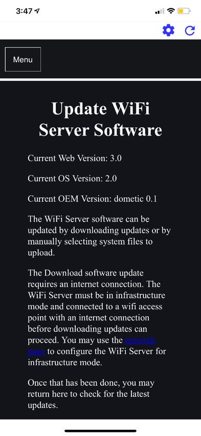
Dometic Interact                                                              Explanation of Symbols and Safety Instructions

1 Explanation of Symbols and                                   • The installation must comply with all applicable local or
                                                                 national codes, including the latest edition of the
Safety Instructions                                              following standards:
This manual has safety information and instructions to           U.S.A.
help you eliminate or reduce the risk of accidents and
                                                                  – ANSI/NFPA70, National Electrical Code (NEC)
injuries.
                                                                  – ANSI/NFPA 1192, Recreational Vehicles Code

1.1 Recognize Safety Information                                  – ANSI Z21.57, Recreational Vehicles Code
                                                                 Canada
D This is the safety alert symbol.                                – CSA C22.1, Parts l & ll, Canadian Electrical Code
     It is used to alert you to potential physical injury
     hazards. Obey all safety messages that follow this           – CSA Z240 RV Series, Recreational Vehicles
     symbol to avoid possible injury or death.
                                                               1.4 General Safety Messages
1.2 Understand Signal Words
A safety symbol and/or signal word identify safety             ! WARNING: FIRE, IMPACT, AND/OR
messages and indicate the hazard severity.                          EXPLOSION HAZARD
                                                                    Failure to obey the following warnings could result in
D DANGER!                                                           death or serious injury:
     Indicates a hazardous situation that, if not avoided,     • Use only Dometic replacement parts and components
     will result in death or serious injury.                     that are specifically approved for use with the
                                                                 appliance.
! WARNING:                                                     • Use care when diagnosing and/or adjusting
     Indicates a hazardous situation that, if not avoided,
                                                                 components on a powered unit.
     could result in death or serious injury.
                                                               • Do not modify this product in any way. Modifications
! CAUTION:                                                       can be extremely hazardous.
     Indicates a hazardous situation that, if not avoided,     • Do not allow children to play with this product or with
     could result in minor or moderate injury.                   fixed controls (if applicable).
NOTICE: Used to address practices not related to
physical injury.
                                                               2 General Information
     Indicates additional information that is not related to
I    physical injury.                                          Dometic Interact provides a central control and
                                                               monitoring hub for the appliances in your recreational
                                                               vehicle (RV). All of the LCDs in the RV communicate with
1.3 Supplemental Directives                                    each other continuously over the RV-C bus. When one
                                                               LCD is down, the others can continue to operate.
To reduce the risk of accidents and injuries, please
observe the following directives before proceeding to          Dometic Interact does not replace the actual hardware
operate this appliance:                                        controllers for the systems within the coach; it is a display
                                                               that sends the signals and commands to various
• Read and follow all safety information and instructions.     components (such as load boxes) regarding the actions
• Read and understand these instructions before                that should be taken.
  operating this product.

EN                                                                                                                         3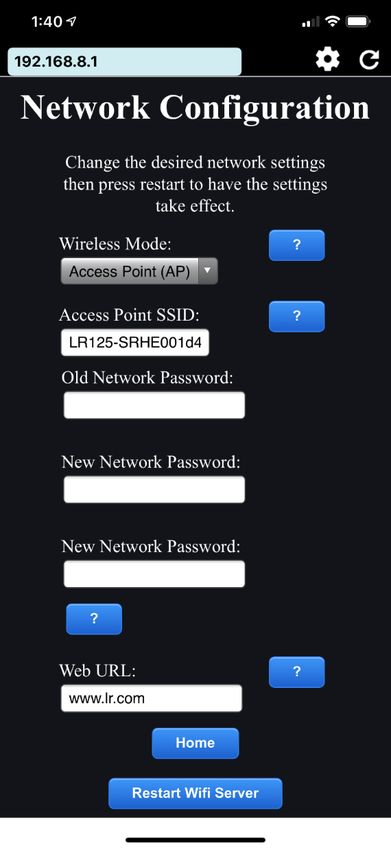
Intended Use                                                                                             Dometic Interact

The Dometic Interact system allows you to:                     The manufacturer accepts no liability for damage in the
                                                               following cases:
• Control the climate, lighting, awnings, slide-outs,
  water systems, and generators from convenient                • Faulty assembly or connection
  locations in and around your vehicle.
                                                               • Damage to the product resulting from mechanical
• Monitor the status of water tank levels, LP gas levels,        influences and excess voltage
  and battery levels from any location.
                                                               • Alterations to the product without express permission
                                                                 from the manufacturer
2.1 Key Features                                               • Use for purposes other than those described in the
Dometic Interact has the following features and benefits         operating manual
when integrated with your RV:                                  Dometic Corporation reserves the right to modify
• Convenient 3.5 in. (89 mm) touch-screen display              appearances and specifications without notice.

• Wireless network control and mobile application
• Single- or multiple-screen interfaces
                                                               4 Operation
• One-touch control for user-programmable modes,
  such as Home, Away, and Sleep                                ! WARNING:        FIRE AND/OR IMPACT HAZARD.
                                                                   Failure to obey the following warnings could result in
• Haptic touch and sound feedback
                                                                   death or serious injury:
• On-screen predictive usage                                   • Avoid improper operation of the unit. Refer to the
• Control and monitoring of your RV's vital and                  operating manuals for the specific products that this
  convenience features, such as:                                 unit controls to understand and obey the applicable
                                                                 safety precautions.
    – Lights
                                                               • Do not allow anyone (including children) with reduced
    – Climate
                                                                 physical, sensory, or mental capabilities, or lack of
    – Generator                                                  experience and knowledge to use this product, unless
    – Inverter                                                   they have been given supervision or instruction
                                                                 concerning the use of this product by a person
    – Water holding tanks                                        responsible for their safety.
    – Water pump                                               NOTICE: You can use multiple screens for different
    – Awning                                                   operations at the same time, but avoid performing a
                                                               single operation from multiple screens.
    – Alarm clock
                                                               Dometic Interact can be operated from the onboard
    – Coach battery
                                                               touch-screen display, or via the mobile application
                                                               (available for download on most mobile devices).
3 Intended Use                                                 Refer to the following sections for more information about
                                                               touch-screen and mobile application navigation and use,
Dometic Interact is intended to be used in conjunction
                                                               including information about:
with the existing control and/or monitoring devices
within your RV. It creates a central hub that you can use to   • UI screens and buttons
efficiently control and monitor your appliances, via the
onboard touch-screen display or from your mobile               • Control and monitoring functionality
application.                                                   • Prerequisites (mobile only)

4                                                                                                                     EN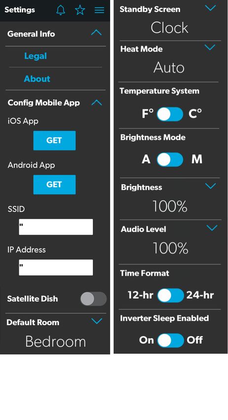
Dometic Interact                                                                                                  Operation

4.1 Touch-Screen Navigation and                              • Room Screens
Use                                                          • Clock Screen

This section describes how to use Dometic Interact from      The following table describes the buttons that are used
the touch-screen display.                                    for general navigation of the various screens and to select
                                                             settings.
Refer to Mobile Application Navigation and Use to learn
how to operate the control using the mobile application.     Button     Description
                                                                        Tap this icon to change the layout of the Main Nav-
I The  screens presented in this section vary according
  to the available appliances and the layout of your RV.
                                                                        igation screen to list view.
                                                                        Tap this icon to change the layout of the Main Nav-
                                                                        igation screen to grid view.
4.1.1 Main Navigation Screen and Icons                                  Tap this icon to close the current screen and return
                                                                        to the previous screen.
The Main Navigation screen is the default landing screen
that you will use to navigate through the various areas of              Tap this icon to reach the Programs screen.
the control.
                                                                        Tap this icon to reach the Notifications screen.

                                                                        Tap this icon to return to the Main Navigation
                                                                        screen.
                                                                        Use toggle buttons to enable or disable functions.

                                                                        Use tumblers to select from a list of available
                                                                        options. Tumblers can be horizontal or vertical.
                                                                        Scroll to bring the desired setting to the middle
                                                                        position.
                                                                        Use sliders to increase or decrease the intensity of
                                                                        certain settings, such as light sources. Sliders can
                                                                        be horizontal or vertical. Slide the dot along the
                                                                        bar to the desired intensity. The indicator shows
                                                                        the intensity level as a percentage.
1 Main Navigation Screen

The Main Navigation screen provides access to the
following screens:
• Climate Screens
• Mechanical Screen
• Lights Screen
• Power Screen
• Notification Screen
• Tanks Screen
• AGS Screen
• Fuses Screen
• Settings Screen

EN                                                                                                                          5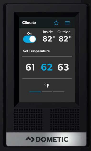
Operation                                                                                             Dometic Interact

4.1.2 Climate Screens                                      From these screens, you can control or monitor the
                                                           following functions:
The Climate screens allow you to control and monitor the
climate within your RV, such as cooling, heating, and AC   • Current Temperatures: These indicate the current
fan.                                                         indoor and outdoor air temperatures.

                                                                  The outdoor temperature sensor may not be
                                                           I      available on all models.
                                                           • Power: The default state for this button is off. Tap the
                                                             toggle button once to turn climate control on. The
                                                             applicable climate control appliance will be activated,
                                                             depending on the set temperature and the
                                                             temperature type currently selected.
                                                           • Set Temperature: This area displays a set of numbers
                                                             ranging from 40–90 °F (4–32 °C) in ascending order.
                                                             Use the tumbler to select your desired temperature
                                                             setting.
                                                           • Climate Mode: There are four climate mode options:
                                                             Auto, Fan Only, Heat, and Cool. Tap the center bar of
                                                             the lower section indicator to view the climate mode
                                                             settings. Use the tumbler to select your desired mode:
                                                              – Choose Auto to allow the system to select the
                                                                appropriate operating mode based on the
                                                                configured settings and actual temperature
                                                                readings.
                                                              – Choose Fan Only to turn off the AC or furnace and
                                                                use only the fan for the AC unit.
                                                              – Choose Heat to turn on the furnace or heat pump.
                                                              – Choose Cool to turn on the AC unit.

                                                                  Refer to the Settings Screen section for
                                                           I      information about changing the Heat Mode
                                                                  setting to run the furnace, the heat pump, or in
                                                                  automatic mode.
                                                           • Fan Level: Tap the right bar of the lower section
                                                             indicator to view the fan speed settings for the AC unit.
                                                             There are four fan speed options: low, medium, high,
                                                             and auto.
                                                             Use the tumbler to select your desired fan speed:
                                                              – Choose L, M, or H to set the fan to the low, medium,
                                                                or high setting.

2 Climate Screens

6                                                                                                                 EN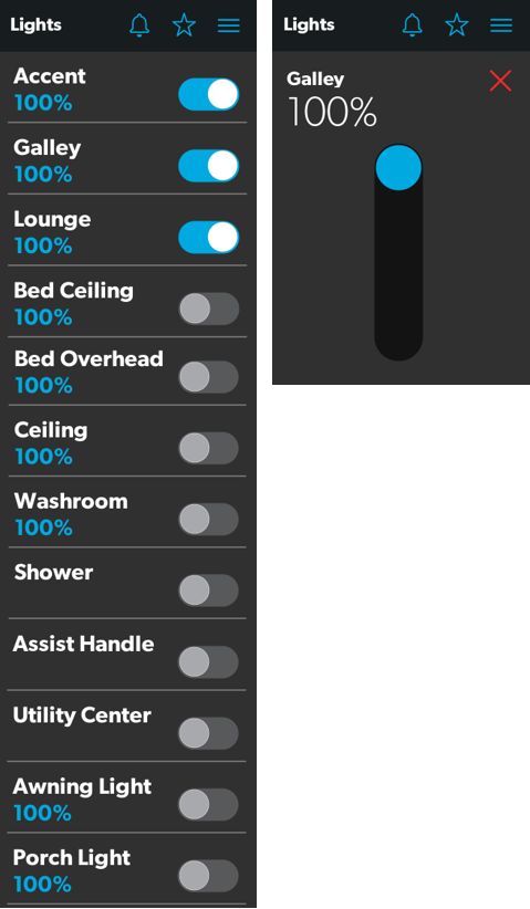
Dometic Interact                                                                                              Operation

   – Choose A to set the fan to the Auto setting, where        • Vent Fan Speed: The Fan Speed buttons control the
     the unit will determine the appropriate fan speed           speed of the galley vent fans. Tap a button to choose
     automatically based on the set temperature and the          the desired vent fan speed from the four available
     actual temperature readings.                                options, which represent the percentages of the
                                                                 maximum fan speed: 25, 50, 75, or 100.
4.1.3 Mechanical Screen                                        • Awnings: The Awning buttons allow you to extend or
                                                                 retract the awning. Awnings will have no control unless
The Mechanical screen allows you to control and monitor
                                                                 the parking brake is engaged. If you attempt to extend
your mechanical appliances, such as awnings and
                                                                 or retract the awnings while the parking brake is not
ventilation fans.
                                                                 engaged, an alert appears.

                                                               4 Parking Brake Alert

                                                                 The Awning buttons function as follows:
                                                                 – Tap the plus button (+) to extend the awning or the
                                                                   minus button (–) to retract the awning, and a pop-up
                                                                   message appears (assuming the parking brake is
                                                                   engaged).

                                                               5 Awning Clear Message
3 Mechanical Screen
                                                                 – After you have verified that the awning is clear of
From this screen, you can control and monitor the
                                                                   obstructions, tap the OK button. The awning is now
following functions:
                                                                   ready to extend or retract.
• Power: The default state for the bath and galley fan
  Power buttons is off. Tap the Power button once to turn
  the fan on.

       The lid must be open before the fan motor turns
I      on. If the lid is closed when you attempt to turn the
       fan motor on, the lid will open automatically.
• Lid Control: The bath and galley fan lids are closed by
  default. Tap the Open or Close button for the galley or
  bath fan lid control to open or close the lids. A white
  outline around the button indicates the status of the lid.

EN                                                                                                                     7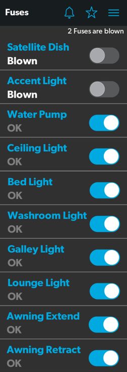
Operation                                                                                              Dometic Interact

4.1.4 Lights Screen                                       • Dimmer/Slider: The light source intensity is
                                                            indicated when the power to the light is activated. Tap
The Lights screen allows you to control and monitor the     the intensity indicator to open the vertical slider screen,
various lighting sources throughout your RV, such as        where you can adjust the light source intensity.
accent, galley, utility lighting, and the other lights.

                                                          4.1.5 Power Screen
                                                          The Power screen allows you to monitor and control the
                                                          available power sources for your RV, such as the battery,
                                                          inverter, and generator.

6 Lights Screen

I The Shower, Assist Handle, and Utility Center lights
  do not dim.

From these screens, you can control and monitor the
following functions:
• Power Buttons: The power buttons are used to turn a
  particular light on and off. Tap the toggle or on/off
  buttons as desired to turn the lights on or off.

                                                          7 Power Screen

8                                                                                                                  EN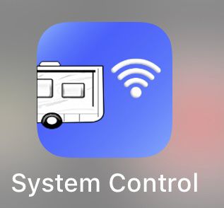
Dometic Interact                                                                                                       Operation

From the Power screen, you can control and monitor the            • Charger Stage: This indicator shows the charger
following functions:                                                status of the onboard charger, as described in the
                                                                    following table:
• Inverter Power: Use the toggle button to turn the
  inverter ON or OFF. The Operating Mode indicator                Number Status          Description
  displays the operating mode of the inverter:                    0          Disabled    The charger is disabled.
   – Pass Thru indicates the inverter is bypassed, when           1          Not         The charger is enabled, but it is not
     the shore power is hooked up.                                           Charging    charging (typically due to a lack of
                                                                                         AC power).
   – Inverting indicates the inverter is Enabled.
                                                                  2          Bulk        The charger is in the initial stage of
   – Waiting to Invert indicates the inverter is Enabled but                             the three-stage charging cycle.
     is not yet actually producing AC power.
                                                                  3          Absorption The charger is in the second stage of
   – Load Sensing indicates the inverter is waiting for the                             the three-stage charging cycle.
     load.                                                        4          Over        The charger is over-charging the bat-
                                                                             Charge      teries (this status is rare).
  The following modes display on the inverter LCD
  screen. Refer to the Xantrex Inverter Manual for more           5          Equalize    The charger is equalizing the
                                                                                         batteries.
  information.
                                                                  6          Float       The charger is in the third stage of
   – Battery mode indicates that the inverter is running                                 the three-stage charging cycle.
     and supplying AC power to the loads from battery.
                                                                  7          Constant    The charger is providing constant
   – Grid mode indicates that the inverter is charging the                   Voltage     voltage charging (typically used
     battery with AC voltage from shore power, but it is                                 during single-stage charging cycles).
     bypassing the inverter supply of AC power to the
     loads directly from the shore power.                         • Charger Current: This indicator shows the current
                                                                    that the charger is drawing from shore power.
   – Off appears when the inverter is either off, or it is in
     an error, fault, or warning state.                           • AC Input Current: This indicator shows the input
                                                                    current being drawn from shore power.
       If the inverter is in an error, fault, or warning state,
I      the error code will be indicated on the inverter           • AC Load Current: This indicator shows the current
       LCD screen in the inverter compartment.                      that the loads are drawing directly from shore power,
                                                                    bypassing the inverter.
• Battery: These indicators provide voltage readings for
  the chassis (engine) and house (coach) batteries,               • Generator: These options control both input and
  respectively.                                                     output, so you can monitor and control the onboard
                                                                    generator:
• Load Wattage: This indicator displays the power
  consumed by the load from the inverter when in                      – The hours indicator shows the number of hours that
  battery mode.                                                         the generator has run.

EN                                                                                                                                9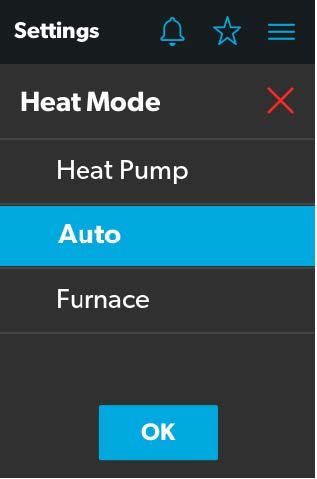
Operation                                                                                                  Dometic Interact

     – The status indicator shows the state of the                 manually stop the generator, the AGS system does not
       generator, as described in the following table:             attempt to start it up again.

Number Status                       Description                  The Power screen also has a settings icon that you can tap
0            Stopped                The generator is stopped.    to reach the Advanced Inverter Settings screen.
1            Pre-Heat               The generator is preheat-
                                    ing. This is done prior to
                                    the cranking cycle.
2            Cranking               The generator is starting.
3            Running                The generator is running.
4            Priming                The generator is advanc-
                                    ing fuel.
5            Fault                  There is a fault.
6            Engine Run Only        The generator is running,
                                    but not producing AC
                                    power.
7            Test Mode              This status is unused.
8            Voltage-Adjust-Mode This status is unused.
9            Fault-Bypass-Mode      This status is unused.
10           Configuration-Mode     This status is unused.

          For a complete list of generator statuses, refer to
I         the RV-C Specifications PDF.
     – The START and STOP buttons control the output of
       the generator. Tap the START button to start the
       generator. The status changes to Cranking, and then
       to Running. A pop-up message should also appear.

8 Ventilation Alert

• AGS: The Automatic Generator Start (AGS) indicator
  shows the status of the auto generator, which can be
  either ON or OFF or disabled due to Quiet Time or
  External Activity.
     There is also a CLEAR AGS button; when external
     activity is detected, tap this button to override the
     external activity demand and turn the AGS on.
     External activity is a mechanism used to disable the
     AGS if the generator is manually stopped or started.
     This is a safety feature implemented so that if you

10                                                                                                                     EN
Dometic Interact Operation
The advanced inverter settings are for technicians only,
and a pop-up message appears when you tap the
advanced inverter icon.
10 Advanced Inverter Settings Notification
Tap the CANCEL button to return to the Power screen, or
tap the GO ANYWAY button to proceed to the
Advanced Inverter screen.
I There are some configurable settings available from
the inverter LCD display.
From the Advanced Inverter Settings screen, technicians
can control or monitor the following functions by tapping
the expand/contract arrows, toggle buttons, EDIT, and
OK buttons as applicable:
• Inverter Ignition Control
• LBCO Voltage
• LBCO Shutdown Delay Timer
• LBCO Recovery Voltage
• Power Save Time
• Power Save Mode
• Output Voltage
• Inverter Output Power Limit
• Inverter Output Power Limit Timer
• Transfer Mode
• Utility AC Under Voltage Level
• Custom Absorption Voltage
• Custom Float Voltage
Complete the following steps to change the default value
to a different value:
9 Advanced Inverter Settings Screens
EN 11Operation Dometic Interact
1. Tap the expand/contract button for the feature
setting that you want to update.
2. Based on the available options for the selected
feature, complete one of the following actions:
– Tap an option from the list.
– Tap the toggle button to activate/deactivate the
feature.
– Tap the EDIT button to view the available settings for
the value.
3. If the EDIT button is selected:
a. Change the value as desired.
b. Tap the OK button to confirm the change and
return to the Advanced Inverter Settings screen.
4. Repeat the previous steps to set the other feature
settings as applicable.
5. After all updates are complete, tap the exit (x) icon to
leave the feature settings mode and return to the
Power screen.
4.1.6 AGS Screen
The AGS (Auto-Gen Start) screen allows you to monitor
and control the automatic generator settings, such as the
scheduled on/off times, scheduled run times, and
voltages.
11 AGS Screen
12 ENDometic Interact Operation
From this screen, you can control and monitor the • Generator Exerciser: Use the toggle button to
following functions: enable or disable the generator exerciser.
• Auto Charger: Use this toggle button to enable or When you enable this setting, the Ventilation Alert
disable the auto charger. The auto charger is disabled pop-up message appears. The alert message does not
by default. When you enable the auto charger, a pop- appear when the generator activates based on the set
up message appears. schedule. The generator runs as scheduled if the
ignition is turned off. If the ignition is turned on during
a particular day that the generator is scheduled to run,
it would skip running the generator that day unless the
ignition is turned off.
The following generator exerciser settings are
available:
12 Ventilation Alert – Days: Tap the desired days to specify the days on
which the generator exerciser should run.
The AGS becomes disabled if the ignition is turned on.
If you attempt to enable the auto charger while the – Run Time: This tumbler controls the duration for the
ignition is on, a pop-up message appears. generator exerciser. Use the tumbler to set your
desired time setting (10–2400 minutes).
– Start Time: These tumblers control the time at
which the generator exerciser should start. Use the
available tumblers (hour and minute) to set your
desired time settings.
13 Ignition Alert 4.1.7 Tanks Screen
The following auto charger settings are available: The Tanks screen allows you to monitor and control the
holding tanks, such as the fresh, gray, and black water
– Quiet Time: Use the available tumblers (hour and
tanks.
minute) to set the desired quiet time start and end
times. The generator is turned off automatically
during the specified quiet time.
– Start Voltage: Use the tumbler to set your desired
voltage setting (10 V–12.9 V). The default setting is
10.5 V. The Start Voltage tumbler controls the
threshold voltage under which the AGS must turn
on.
– Time Under: Use the tumbler to set your desired
timer setting (0–10 min). The Time Under tumbler
specifies the timer delay before the AGS starts,
when the system drops below the set threshold
voltage.
• AGS Climate: These options enable the climate 14 Tanks Screen
controls to run the air conditioner and heat pump off
the generator when no shore power is available.
EN 13Operation Dometic Interact
From this screen, you can monitor and control the 4.1.8.1 General Info Section
following functions:
Use this section of the Settings screen to find general
• Indicator Bars: The horizontal bars indicate the fluid legal information and to learn about the system:
levels for the various tanks (percent full), which are
• Tap Legal to open the Legal window.
monitored continuously by the sensors attached to the
outside of the tanks. These indicators are for
monitoring purposes only and do not have any control
functions
• Water Pump: Use this toggle button to turn the water
pump on or off. The water pump is deactivated by
default.
4.1.8 Settings Screen
The Settings screen allows you to control and configure
the various aspects of the system and control, such as
screen brightness, and audio levels.
16 Legal Window
• Tap About to open the About window.
17 About Window
4.1.8.2 Config Mobile App Section
Use this section of the Settings screen to configure the
mobile application connection settings from the touch-
screen display:
Tap the GET button to open a window that contains a
scannable QR code, which leads to the mobile
application download from the App Store or Google Play
15 Settings Screen
Store.
Refer to the sections that follow for more information
about the various sections of the Settings screen.
14 ENDometic Interact Operation
4.1.8.4 Default Room Section
Use this section of the Settings screen to set the default
room that appears on the Main Navigation screen:
1. Tap the EDIT button to open the Default Room
window.
18 QR Code Window - iOS
19 QR Code Window - Android
• SSID: This text-only indicator displays the name of the
network to which the multiplex system is connected.
20 Default Room Window
• IP Address: This numeric indicator displays the IP
address where the mobile app should be directed. For 2. Choose from the list of available rooms (Bedroom,
example, the indicator will display IP address Entry, or Bathroom).
192.168.8.1 if the Wi-Fi device is in Access Point mode, 3. Tap the OK button to save your selection and return
and display a different IP addess if it is in Infrastructure to the Settings screen.
mode.
4.1.8.3 Satellite Dish Option
Use the Satellite Dish toggle button to turn the satellite
dish on or off.
I This option will display on the Settings screen, even
if a satellite dish is not installed.
EN 15Operation Dometic Interact
4.1.8.5 Standby Screen Section
Use this section of the Settings screen to set the screen
that should appear when you are outside of the sensing
range of the proximity sensor:
1. Tap the EDIT button to open the Standby Screen
window.
22 Heat Mode Window
2. Choose from the list of available heat modes:
– Heat Pump: Only the heat pump runs when the
coach requires heating.
– Auto: The furnace and/or heat pump will run when
the coach requires heating. The furnace will only
21 Standby Screen Window
turn on if the temperature drops below the set point.
2. Choose from the list of available display options: The furnace is used as a secondary boost for the heat
pump if the temperature gets cold enough. Auto is
– Dimmed: The screen dims to 30% brightness until the default setting for Heat mode. When in this
the proximity sensor senses movement. mode and:
– Clock: The screen displays the Clock screen until
– If the outside temperature is above 40 °F (4 °C),
the proximity sensor senses movement. Refer to the
and the inside temperature is less than the Heat
Clock Screen section for more information. Set Point, then the heat pump will be on.
– Go To Sleep: The screen goes black until the
– If the difference between the inside temperature
proximity sensor senses movement.
and the Heat Set Point is more than 5 °F (3 °C),
3. Tap the OK button to save your selection and return then the furnace will be on.
to the Settings screen. – If the outside temperature is below 40 °F (4 °C),
then the furnace will be on even when the differ-
When you move into the sensing range of the
I proximity sensor, the display will show the start
ence between the inside temperature and the
Heat Set Point is less than 5 °F (3 °C).
page that you selected.
– Furnace: Only the furnace runs when the coach
4.1.8.6 Heat Mode Section requires heating.
Use this section of the Settings screen to set the method 3. Tap the OK button to save your selection and return
of heating: to the Settings screen.
1. Tap the EDIT button to open the Heat Mode window.
4.1.8.7 Temperature System Option
Use the Temperature System toggle button to set your
desired temperature readings (in degrees Centigrade or
Fahrenheit).
16 ENDometic Interact Operation
The side of the toggle button that holds the dot indicates
the current selection.
4.1.8.8 Brightness Mode Option
Use the Brightness Mode toggle button to choose
between Auto (A) or Manual (M) adjustment modes:
• When the auto option is selected, the brightness is
adjusted according to the ambient light sensor values.
• When the manual option is selected, you can adjust the
screen brightness manually.
4.1.8.9 Screen Brightness Option
Use the Screen Brightness slider to manually set your 23 Programs Screen
desired screen brightness level (shown as a percentage
The Programs screen is the main screen from which pre-
of full intensity).
configured programs and scenes can be monitored,
In order to set the screen brightness, the manual enabled, or disabled. You can complete the following
brightness mode must be selected. actions from this screen:
• Tap the star icon to open the Programs screen.
4.1.8.10 Audio Level Option
• Tap the exit (x) icon to close the Programs screen and
Use the Audio Level slider to set your desired audio level
return to the previous screen.
intensity for the control (shown as a percentage of full
intensity). • Tap any program button to start running the program.
• Rain: The button closes the lids of both the vent fans.
4.1.8.11 Time Format Option
Use the Time Format toggle button to set your desired • Fresh Air: The button opens the lids of both vent fans.
time format (in 12-hour or 24-hour formats). • INT Lights On: The button turns all the interior lights
The side of the toggle button that holds the dot indicates ON.
the current selection. • INT Lights Off: The button turns all the interior lights
OFF.
4.1.8.12 Inverter Sleep Enable Option
• EXT Lights On: The button turns all the interior lights
Use the Inverter Sleep on/off button to make the system ON.
turn the inverter off at startup.
• EXT Lights Off: The button turns all the interior lights
OFF.
4.1.9 Programs Screen
• Wake Up: The button turns the Accent, Galley, and
The Programs screen allows you to control the Bed ceiling lights ON.
predefined scenes with one touch of a button.
• Good Night: The button turns ALL the lights OFF.
4.1.10 Fuses Screen
The Fuses screen allows you to monitor and control the
software fuses for the various system components.
EN 17Operation Dometic Interact
A software fuse will display as “blown” if the load draws 4.1.11 Bedroom Screen
more current than the allowed limit.
The Bedroom screen allows you to monitor and control
the available components within the bedroom area of
your RV, such as the climate and lights.
25 Bedroom Screen
From this screen, you can monitor and control the
following functions:
• Temperature: Use the tumbler to select your desired
temperature.
• Lights: Use the toggle button for the desired light
source to turn it off or on. The light source brightness is
indicated as a percentage of the maximum intensity.
24 Fuses Screen Tap the brightness indicator for the desired light to
adjust the intensity via vertical slider.
Each controlled component includes a toggle button
indicating the fuse status: OK or blown.
4.1.12 Bathroom Screen
When the system detects a high inrush current or over-
voltage condition, the software blows the fuse for that The Bathroom screen allows you to monitor and control
particular output. the available components within the bathroom area of
your RV, such as ventilation, water pump, and lights.
Use the toggle button to reset a blown fuse, which sets it
to the enabled (OK) state.
When a fuse blows, the system produces a notification by
showing a number beside the bell icon at the top of each
screen. The system also plays a sound to notify you.
The number on the notification bell icon remains until you
open the Notifications screen and close all notifications,
one-by-one.
Refer to the Notifications Screen section for more
information.
18 ENDometic Interact Operation
27 Entry Screen
26 Bathroom Screen
From this screen, you can monitor and control the
From this screen, you can monitor and control the
following functions:
following functions:
• Entry Lighting: Use the toggle button for the desired
• Lights: Use the toggle button for the desired light
light source to turn it off or on.
source to turn it off or on. The light source brightness is
indicated as a percentage of the maximum intensity. The All Entry Lights toggle button controls all three
Tap the brightness indicator for the desired light to I entry light sources (porch, awning, and utility).
adjust the intensity via vertical slider.
• Awnings: The Awning buttons allow you to extend or
• Fan: Use the power toggle button to turn the fan motor retract the awning. Awnings will have no control unless
on or off. the parking brake is engaged.
The lid must be open before the fan motor turns If you attempt to extend or retract the awnings while
I on. If the lid is closed when you attempt to turn the the parking brake is not engaged, an alert appears.
fan motor on, the lid will open automatically.
• Lid Control: Tap the Open or Close button to open or
close the lids. A white outline around the button
indicates the status of the lid.
• Water Pump: Use this toggle button to turn the water
pump on or off.
28 Parking Brake Alert
4.1.13 Entry Screen The Awning buttons function as follows:
The Entry screen allows you to monitor and control the – Tap the plus button (+) to extend the awning or the
available components within the entry area of your RV, minus button (–) to retract the awning, and a pop-up
such as lighting and awnings. message appears (assuming the parking brake is
engaged).
EN 19Operation Dometic Interact
• Battery Levels: The battery level indicator monitors
and displays the battery voltage level.
4.1.15 Notification Screen
The Notification screen allows you to monitor system fault
status messages, such as blown fuse notifications.
29 Awning Clear Message
This screen can be reached by tapping the bell icon at the
– After you have verified that the awning is clear of top of any screen.
obstructions, tap the OK button. The awning is now
ready to extend or retract.
4.1.14 Clock Screen
The Clock screen allows you to monitor various system
statuses, such as temperatures, time and date, and
humidity.
This screen appears when the proximity sensor is out of
the threshold distance (sensing range). For this screen to
appear in standby mode, you must select the Clock
standby option from the Settings screen.
31 Notification Screen
From this screen, you can complete the following actions:
• View and Clear Notifications: Notifications appear
with a banner when you open the Notification screen.
– To clear an individual message, tap the exit (x) icon
for that message.
– To clear all messages, tap the CLEAR ALL button.
• View Diagnostics Information: You can view
diagnostics information for each notification.
– To view the diagnostics information for the
30 Clock Screen notifications, tap the SHOW DM RVC button. The
Diagnostics Message window appears.
From this screen, you can monitor the following system
statuses:
• Temperature: This inside and outside temperatures
are presented in either degrees Celcius or Fahrenheit,
which you can define from the Settings screen.
• Time and Date: The current time and date are
displayed in the middle of the screen.
• Humidity: The humidity is shown as a percentage,
coming from the onboard humidity sensor reading.
20 ENDometic Interact Operation
• To download the application for Android devices, visit
the Google Play Store.
After you have downloaded the application onto your
mobile device, you can proceed to make the initial
connection to the control.
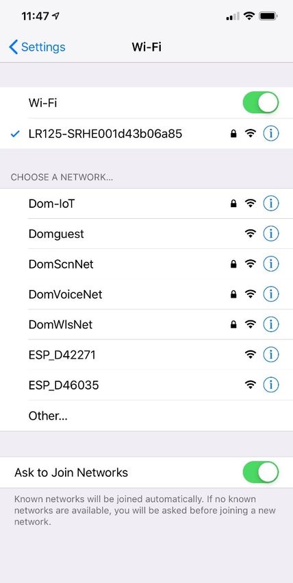
4.2.2 Initial Connection
Complete the following steps to make the initial
connection to the control from your mobile device:
1. Move into the vicinity of the control to ensure
successful connection.
32 Diagnostics Message Window 2. Open your device settings and search for available
Wi-Fi networks.
– To clear an individual message, tap the exit (x) icon
for that message. 3. Locate and connect to the Wi-Fi network named
LR-125.
– To clear all messages, tap the CLEAR ALL button.
4.2 Mobile Application Navigation
and Use
This section describes how to use Dometic Interact from
the downloadable mobile application. Refer to Touch-
Screen Navigation and Use to learn how to operate the
control using the onboard touch-screen display.
I Connecting to the Dometic Interact mobile
application will update the clock on the touch
display.
4.2.1 Prerequisites
Before you can connect to Dometic Interact with a mobile
device, you must first download the System Control
application onto your device.
34 Wi-Fi Networks
4. Enter the default password, which is
YourPassPhrase.
You should now be successfully connected to Dometic
Interact. You can proceed to change the password
settings, if desired.
33 System Control App
• To download the application for Apple devices, visit
the App Store.
EN 21Operation Dometic Interact
4.2.3 Password and SSID Settings
I When you change the SSID or Password, the Wi-Fi
module will reset and you must log in again using the
new credentials.
Complete the following steps to change the password:
1. Tap the Settings icon once.
2. Tap Set URL, and then enter 192.168.8.1.
3. Tap the Settings icon once again, and then tap
Network Page.
36 Network Configuration Update Menu
I Your new password must be at least eight characters
(and include letters, number, or combination) to
avoid a lockout scenario.
If the original password you use to make the update
is less than eight characters, the application will
accept it. However, the application will not allow
you to log in later with an invalid password. You
would have to reset the Wi-Fi module. Using an eight
or more character password should avoid this
lockout situation.
35 Network Configuration Menu 4. Update your password settings.
The following screen appears, where you can update • Wireless mode. This option allows you to define the
your password as desired. wireless mode.
– Access Point: The Wi-Fi server module will act as an
access point, so that the other personal mobile
devices will connect to it directly.
– Infrastructure: The Wi-Fi server module will be
connected through any other Wi-Fi device or
modem, such as Winegard.
22 ENDometic Interact Operation
• SSID: The default SSID and user name for this multiplex • System Configuration: Tap this tab to reach the
system will look similar to “LR125-xxxxxx” (xxxxxx = System Configuration screen, where you can elect to
serial number). You may also customize the SSID. show metric values, or enable the splash screen.
5. After your password and WiFi settings are updated,
restart your Wi-Fi server and log in with the new
credentials.
4.2.4 Navigation and Use
After successful connection to the Dometic Interact Wi-Fi
network, you are ready to begin using your mobile device
to control the available components within your control
configuration.
The mobile application landing page includes the
following navigation options:
38 System Configuration Screen
• Update Software: Tap this tab to reach the Update
WiFi Server Software screen, where you can view and
manage the current software versions.
37 Landing Page Navigation
From the landing page, you can tap the following tabs to
reach the desired screen:
• Main Screen: Tap this tab to reach the Main
Navigation screen. Once you reach the Main
Navigation screen, you can navigate to and use the
main screens just as described in the Touch-Screen
Navigation and Use section.
39 Update WiFi Server Software Screen
EN 23Maintenance Dometic Interact
• View Log: Tap this tab to reach the LR 125 Boot Log NOTICE: Do not use abrasive cleaning materials or
screen, where you can choose to load the boot log for harsh chemicals on the touch-screen display, or damage
the Wi-Fi server. to the product can occur.
If the touch-screen display becomes dirty, clean it with a
soft, dry cloth, or use compressed air to loosen debris
from the external orifices.
To remove hard dirt or grime, a slightly damp cloth with
non-abrasive cleaning product is acceptable; however,
take care not to damage the touch-screen display.
5.2 Preventive Maintenance
Use the following tips to ensure that your control
continues to work properly:
• Ensure that the touch-screen display and PCB are
operated between -4 °F to 140 °F (-20 °C to 60 °C).
• Ensure that you power on the control system
occasionally during extended periods of non-use.
40 Boot Log Screen
• Close: Tap this tab to close the mobile application. 6 Troubleshooting
5 Maintenance ! WARNING: FIRE AND/OR ELECTRICAL SHOCK
HAZARD
Use care when diagnosing, repairing, adjusting,
! WARNING: FIRE AND/OR ELECTRICAL SHOCK
and/or cleaning components on a powered unit.
HAZARD
Failure to obey this warning could result in death or
Use care when diagnosing, repairing, adjusting, serious injury.
and/or cleaning components on a powered unit.
Failure to obey this warning could result in death or This section describes how to troubleshoot common
serious injury. errors that may be encountered on Dometic Interact.
This section describes how to care for and maintain
Dometic Interact. Refer to the following sections for I Refer to your inverter operating manual for
troubleshooting information and to obtain customer
information about care, cleaning, and preventive service center information. Contact the
maintenance of the product. manufacturer customer service department for
inverter-related issues.
5.1 Care and Cleaning The table that follows describes some common errors
that may be encountered with the control, their possible
causes, and the recommended corrective actions.
! WARNING: FIRE AND/OR SHOCK HAZARD.
Do not allow water to splash on or pour into a Contact Dometic Customer Support Center
powered unit. Failure to obey this warning could at 1-800-544-4881, or email
result in death or serious injury: customersupportcenter@dometic.com for any other
assistance.
24 ENDometic Interact Disposal
Error Possible Cause Recommended Corrective Action
There is power loss to Dometic There is too much load on the circuit. Turn off the battery switch near the entry steps. Wait 10
Interact. seconds, and turn the battery switch on.
The screen does not wake up. You are not within range of the display Move closer to the LCD screen, or tap it once to turn it
proximity sensor. on.
The coach lights are not turning There is a blown software fuse, or the Examine the Dometic Interact Fuses screen and reset
on. LED light needs to be replaced. the blown fuse, or replace the LED bulb.
Recycle the power through the battery switch at the
entry way
The AC will not turn on or off. The AC is in a time-delayed start up, or The AC can take up to three minutes to respond to on/
the AC circuit breaker has tripped. off commands.
Reset the circuit breaker, if needed.
You are unable to locate or con- You are not within range of the LR-125 Seek a stronger Wi-Fi signal.
nect to the LR-125 Wi-Fi server. Wi-Fi module. There is no Wi-Fi connec- Contact the Dometic Customer Support center to
tion or the connection has been lost. reset the modem.
There is a water pump failure. There is a blown software fuse. Examine the Dometic Interact Fuses screen and reset
the blown fuse, if applicable.
There is a satellite dish failure. There is a blown software fuse, or the Examine the Dometic Interact Fuses screen and reset
satellite dish is disabled. the blown fuse, or enable the satellite dish in the Set-
tings screen.
The touch-screen is The system might be frozen. Reboot the system by interrupting the power supply
unresponsive. for ten seconds.
There is audio trouble. The audio level is set too low. Adjust the audio level in the Settings screen, and
reboot the system.
The tank level readings are The RV is not level or stationary. Bring the RV to a complete stop and ensure that it is
inaccurate. level.
The generator fails to exercise. The AGS is turned off, the ignition safety Turn on the AGS, remove the key from the vehicle igni-
interlock is enabled, or the settings are tion, or adjust the time settings.
incorrect. Go to Power screen and press the CLEAR AGS button
An external activity such as a quiet time on the bottom of the screen.
or a manual shut off has occurred.
The vent fan will not operate. The lid is stuck in the closed position. Check the lid and use the manual switch to open or
The vent fan fuse may have blown. loosen the lid.
Replace the 4 A fuse on the vent fan.
7 Disposal LIMITED ONE-YEAR WARRANTY
Place the packaging material in the appropriate LIMITED ONE-YEAR WARRANTY AVAILABLE AT
M recycling waste bins, whenever possible. Consult a WWW.DOMETIC.COM/WARRANTY.
local recycling center or specialist dealer for details IF YOU HAVE QUESTIONS, OR TO OBTAIN A COPY OF
about how to dispose of the product in accordance THE LIMITED WARRANTY FREE OF CHARGE, CONTACT:
with all applicable national and local regulations.
DOMETIC CORPORATION
CUSTOMER SUPPORT CENTER
5155 VERDANT DR
ELKHART, INDIANA, USA 46516
1-800-544-4881 OPT 1
EN 25Sommaire Dometic Interact
Liste des centres de service et des revendeurs
Visiter : www.dometic.com
Lire attentivement ces instructions. Ces instructions DOIVENT rester avec ce produit.
Sommaire
1 Explication des symboles et 4.2 Navigation et utilisation de
des consignes de sécurité . . . . . . . . . . . . . . . . 27 l’application mobile . . . . . . . . . . . . . . . . . . . . . 47
1.1 Reconnaître les consignes de sécurité . . . . . . 27 4.2.1 Conditions préalables . . . . . . . . . . . . . 47
1.2 Comprendre les mots-indicateurs. . . . . . . . . . 27 4.2.2 Première connexion . . . . . . . . . . . . . . 48
1.3 Directives supplémentaires . . . . . . . . . . . . . . . 27 4.2.3 Paramètres du mot de passe et du
1.4 Messages de sécurité d’ordre général . . . . . . 27 SSID . . . . . . . . . . . .. . . . . . . . . . . . . . . . 48
4.2.4 Navigation et utilisation. . . . . . . . . . . . 49
2 Informations générales . . . . . . . . . . . . . . . . . . 28
2.1 Caractéristiques principales . . . . . . . . . . . . . . 28 5 Maintenance . . . . . . . . . . . . . . . . . . . . . . . . . . . . 51
5.1 Entretien et nettoyage . . . . . . . . . . . . . . . . . . . .51
3 Indication . . . . . . . . . . . . . . . . . . . . . . . . . . . . . 28
5.2 Maintenance préventive . . . . . . . . . . . . . . . . . .51
4 Mode d’emploi . . . . . . . . . . . . . . . . . . . . . . . . . 28
6 Dépannage . . . . . . . . . . . . . . . . . . . . . . . . . . . . . 51
4.1 Navigation et utilisation de l’écran tactile . . . . 29
4.1.1 Écran de navigation principal et icônes . 29 7 Élimination . . . . . . . . . . . . . . . . . . . . . . . . . . . . 53
4.1.2 Écrans Climate (Climat) . . . . . . . . . . . . 30 GARANTIE LIMITÉE DE UN AN . . . . . . . . . . . . . . . 53
4.1.3 Écran Mechanical (Mécanique) . . . . . . 31
4.1.4 Écran Lights (Lumières) . . . . . . . . . . . . 33
4.1.5 Écran Power (Alimentation). . . . . . . . . 34
4.1.6 Écran AGS . . . . . . . . . . . . . . . . . . . . . . 37
4.1.7 Écran Tanks (Réservoirs) . . . . . . . . . . . 39
4.1.8 Écran Settings (Paramètres) . . . . . . . . 39
4.1.9 Écran Programs (Programmes) . . . . . . 43
4.1.10 Écran Fuses (Fusibles) . . . . . . . . . . . . . 44
4.1.11 Écran Bedroom (Chambre) . . . . . . . . . 45
4.1.12 Écran Bathroom (Salle de bain). . . . . . 45
4.1.13 Écran Entry (Entrées) . . . . . . . . . . . . . . 45
4.1.14 Écran Clock (Horloge). . . . . . . . . . . . . 46
4.1.15 Écran Notification . . . . . . . . . . . . . . . . 47
26 FRDometic Interact Explication des symboles et des consignes de sécurité
1 Explication des symboles et 1.3 Directives supplémentaires
des consignes de sécurité Pour réduire les risques d’accident et de blessure,
veuillez respecter les directives suivantes avant de faire
Ce manuel contient des consignes de sécurité et des fonctionner cet appareil :
instructions pour aider l’utilisateur à éliminer ou réduire le
risque d’accidents et de blessures. • Lire et suivre toutes les consignes de sécurité et les
instructions.
1.1 Reconnaître les consignes • Lire et comprendre ces instructions avant d’utiliser ce
produit.
de sécurité
• L’installation doit se conformer à tous les codes locaux
D C’est le symbole d’alerte à la sécurité. ou nationaux applicables, y compris la toute dernière
Il signale des risques de blessures physiques. Obéir édition des normes suivantes :
à tous les messages de sécurité qui suivent ce États-Unis
symbole pour éviter les risques de blessures ou de
mort. – ANSI/NFPA70, Code national de l’électricité (CNE)
– ANSI/NFPA 1192, Code des véhicules récréatifs
1.2 Comprendre les mots-indicateurs – ANSI Z21.57, Code des véhicules récréatifs
Un symbole de sécurité et/ou un mot-clé identifient les Canada
messages de sécurité et indiquent la gravité du danger. – CSA C22.1, Parties l et ll, Code canadien de
l’électricité
D DANGER! – CSA Z240 RV Series, véhicules récréatifs
Indique une situation extrêmement dangereuse qui
entraînera la mort ou des blessures graves si elle
n’est pas évitée. 1.4 Messages de sécurité d’ordre
général
! AVERTISSEMENT :
Indique une situation potentiellement dangereuse
qui entraînera la mort ou des blessures graves si elle
! AVERTISSEMENT : DANGER D’INCENDIE,
D’IMPACT, ET/OU D’EXPLOSION
n’est pas évitée.
Le non-respect de ces avertissements pourrait
entraîner de graves blessures, voire la mort :
! ATTENTION :
Indique une situation potentiellement dangereuse • Utiliser uniquement des pièces et composants de
qui entraînera la mort ou des blessures graves si elle rechange Dometic spécifiquement approuvés pour
n’est pas évitée. une utilisation avec cet appareil.
AVIS : Il est utilisé pour traiter des pratiques non liées à • Faire attention en diagnostiquant et/ou ajustant les
des blessures physiques. composants d’un appareil électrique.
• Ne pas modifier ce produit d’une quelconque
I Indique des informations supplémentaires qui ne
sont pas liées aux dangers physiques. manière. Les modifications peuvent être extrêmement
dangereuses.
• Ne pas autoriser les enfants à jouer avec ce produit ou
avec les commandes fixes (le cas échéant).
FR 27Informations générales Dometic Interact
2 Informations générales – Onduleur
– Réservoirs d’eau
Dometic Interact fournit un concentrateur de contrôle et
de surveillance central pour les appareils de votre – Pompe à eau
véhicule récréatif (VR). Tous les écrans ACL du VR – Auvent
communiquent entre eux en continu via le bus RV-C.
Lorsqu’un écran ACL est en panne, les autres peuvent – Réveils
continuer à fonctionner. – Batterie du véhicule
Dometic Interact ne remplace pas les contrôleurs
matériels réels des systèmes à l’intérieur du véhicule;
il s’agit d’un écran qui envoie les signaux et les commandes
3 Indication
à divers composants (tels que les boîtes de chargement) Dometic Interact est conçu pour être utilisé avec les
en ce qui concerne les actions à entreprendre. dispositifs de contrôle et/ou de surveillance existants
Le système Dometic Interact vous permet de : dans votre véhicule récréatif. Il crée un concentrateur
central que vous pouvez utiliser pour contrôler et
• Contrôler le climat, l’éclairage, les auvents, surveiller efficacement vos appareils, via l’écran tactile
les coulisses, les systèmes d’alimentation en eau, intégré ou depuis votre application mobile.
les serrures de porte et les générateurs depuis des
emplacements pratiques dans et autour de votre Le fabricant n’endosse aucune responsabilité en cas de
véhicule. dommages dans les cas suivants :
• Surveiller l’état des niveaux des réservoirs d’eau, des • Assemblage ou branchement incorrect
niveaux de gaz propane et de la batterie depuis • Endommagement du produit résultant des influences
n’importe quel endroit. mécaniques et d’une tension excessive
• Altération du produit sans la permission expresse
2.1 Caractéristiques principales du fabricant
Dometic Interact présente les caractéristiques et • Utilisation à d’autres fins que celles décrites dans le
avantages suivants lorsqu’il est intégré à votre VR : manuel d’utilisation
• Écran tactile pratique de 3,5 po (89 mm) Dometic Corporation se réserve le droit de modifier
l’apparence et les caractéristiques techniques de
• Contrôle de réseau sans fil et application mobile
l’appareil sans préavis.
• Interfaces à un ou plusieurs écrans
• Commande à une touche pour les modes 4 Mode d’emploi
programmables par l’utilisateur, tels que Home
(Présent), Away (Absent) et Sleep (Veille)
! AVERTISSEMENT : DANGER D’INCENDIE
• Touche haptique et retour sonore ET/OU D’IMPACT.
Le non-respect de ces avertissements pourrait
• Utilisation prédictive de l’écran
entraîner de graves blessures, voire la mort :
• Contrôle et surveillance des fonctions vitales et
• Éviter le fonctionnement incorrect de l’appareil.
pratiques de votre véhicule récréatif, telles que :
Se reporter aux manuels d’utilisation des produits
– Lumières spécifiques contrôlés par cet appareil pour
– Climat comprendre et respecter les consignes de sécurité
applicables.
– Générateur
28 FRDometic Interact Mode d’emploi
• N’autoriser personne (y compris les enfants) ayant des
capacités physiques, sensorielles ou mentales
réduites, ou un manque d’expérience et de
connaissances, à utiliser ce produit, à moins qu’un
contrôle ou des instructions relatives à l’utilisation de
ce produit aient été donnés par une personne
responsable de leur sécurité.
AVIS : Vous pouvez utiliser plusieurs écrans pour différentes
opérations en même temps, mais évitez d’effectuer une
seule opération à partir de plusieurs écrans.
Dometic Interact peut être utilisé à partir de l’écran tactile
intégré ou via l’application mobile (téléchargeable sur la
plupart des appareils mobiles).
1 Écran de navigation principal
Se reporter aux sections suivantes pour plus d’informations
sur la navigation et l’utilisation sur les écrans tactiles et L’écran de navigation principal donne accès aux écrans
mobiles, y compris des informations sur : suivants :
• Écrans et boutons de l’interface utilisateur • Écrans Climate (Climat)
• Fonctionnalité de contrôle et de surveillance • Écran Mechanical (Mécanique)
• Pré-requis (mobile uniquement) • Écran Lights (Lumières)
• Écran Power (Alimentation)
4.1 Navigation et utilisation • Écran Notification
de l’écran tactile
• Écran Tanks (Réservoirs)
Cette section explique comment utiliser Dometic Interact
• Écran AGS
à partir de l’écran tactile.
• Écran Fuses (Fusibles)
Se reporter à Navigation et utilisation de l’application
mobile pour savoir comment utiliser les contrôles à l’aide • Écran Settings (Paramètres)
de l’application mobile.
• Écran Bedroom (Chambre)
I Les écrans présentés dans cette section varient
en fonction des appareils disponibles et de la • Écran Clock (Horloge)
disposition de votre véhicule récréatif.
4.1.1 Écran de navigation principal
et icônes
L’écran de navigation principal est l’écran de destination
par défaut que vous utiliserez pour naviguer dans les
différentes zones du contrôle.
FR 29You can also read