EXTENDED ABSTRACT - Universiti Teknologi Malaysia
←
→
Page content transcription
If your browser does not render page correctly, please read the page content below

EXTENDED ABSTRACT
International Professional Doctoral Symposium 2019

The International Professional Doctoral Symposium
Universiti Teknologi Malaysia, 30th November 2019

 Extended Abstract

Organized by:

School of Graduate Studies
Universiti Teknologi Malaysia
Tel: +607-5537903 (office)
Fax: +607-5537800
Email: graduate@utm.my
Website: www.sps.utm.my

In collaboration with:

UTM Postgraduate Student Society (PGSS-UTM)
Universiti Teknologi Malaysia
Email: ipdocs-submission@utm.my
Website: http://www.utm.my/ipdocs/

 i
International Professional Doctoral Symposium 2019

ISBN: 978-967-2171-04-9

Copyright © 2019 by School of Graduate Studies, Universiti Teknologi Malaysia. All rights
reserved.

No part of this publication may be reproduced, distributed, or transmitted in any form or by
any means, including photocopying, recording, or other electronic or mechanical methods,
without the prior written permission of the publisher, except in the case of brief quotations
embodied in critical reviews and certain other noncommercial uses permitted by copyright
law. For permission requests, write to the publisher, addressed “Attention: Permissions
Coordinator,” at the address below.

Chair
School of Graduate Studies
Universiti Teknologi Malaysia
Aras 8 Menara Razak
Jalan Sultan Yahya Petra
54100 Kuala Lumpur, Malaysia.
https://sps.utm.my/

First Printing, December 2019.

Printed in Malaysia.

 ii
International Professional Doctoral Symposium 2019

Editorial Board

Editors:
Assoc. Prof. Dr. Astuty Amrin
Assoc. Prof. Dr Siti Zaleha Abdul Rasid
Assoc. Prof. Dr. Siti Sophiayati Yuhaniz
Assoc. Prof. Ir. Dr. Saiful Amri Mazlan
Assoc. Prof. Ts. Dr. Mohd Khairi Abu Husain
Dr. Roslina Mohammad

Associate Editors:
Dr. Faizir Ramlie
Dr. Haliyana Khalid
Dr. Mohamad Syazli Fathi
Dr. Mohamed Sukri Mat Ali
Dr. Noor Hamizah Hussain
Dr. Noorlizawati Abd Rahim
Dr. Nurhasmiza Abu Hasan Sazalli
Dr. Pritheega Magalingam
Dr. Rasimah Che Mohd Yusoff
Dr. Rahimah Muhamad

 iii
International Professional Doctoral Symposium 2019

About iPDOCs’19

In bridging the gap between academia and industry, UTM School of Graduate Studies (SPS)
and Post Graduate Student Society (PGSS) invite academics, practitioners and students to
share ideas and present findings from industry-driven research that contribute impactful
solutions to the industrial challenges and enhance the industrial performance. iPDOCs’19
aims to highlight the impacts of industry-driven research and professional doctorate in
developing professional practices, outcomes and achievements in the industrial workplaces.

The purpose of the conference is to share knowledge and experience in research as well as
to establish an academic network. Participants of iPDOCs’19 are professional doctorate
candidates from various faculties in Universiti Teknologi Malaysia. This conference
encourages them to present and defend their work confidently and improve their research.
This could be a platform for the participants to write high-quality articles in the future. It is also
a venue to expose the participants to establish networking and generate discussions for
potential collaborations. This conference provides opportunities for participants to
communicate and learn from each other not only in terms of academic research but also
the culture.

Articles published in the proceedings can be used for references and will be beneficial to
future researchers. Some of the findings can also be beneficial to some organizations which
can apply the result and conclusions in improving their business operations.

 iv

International Professional Doctoral Symposium 2019

 Contents
PREPARATION OF POROUS-CROSS LINKED ENZYME AGGREGATES USING SUCROSE AS POROUS
AGENT …………………………………………………..………………...…………….……………………. 1
Noor Namirah Nawawi, Boon Cheng Kai, Zanariah Hashim, Nardiah Rizwana Jaafar & Rosli Md Illias

SANITARY LANDFILL IS A SOLUTION IN SOLID WASTE MANAGEMENT OR A SILENT THREAT TO
ENVIRONMENT: MALAYSIAN SCENARIO ……………………...……………………….…………..…… 4
Imran Ahmad, Shreeshivadasan Chelliapan, Norhayati Abdullah & Mohd Danish Ahmad

A FUZZY RULE-BASED FAILURE MODE, EFFECT AND CRITICAL ANALYSIS (FMECA) FOR CONTROL
VALVE MAINTENANCE …………………………………………………………………….…………..…… 8
Faizal Abdullah & Mohd Khairi Abu Husain

OPTIMIZATION OF SOIL-NAILED WALL DESIGN USING SLOPE/W SOFTWARE ………………….......12
Mohd Sukry Mohamed, Fathiyah Hakim Sagitaningrum & Samira Albati Kamaruddin

MICROSTRUCTURAL TRANSFORMATION BY COMPOSITIONAL MODIFICATION OF Ti-6Al-4V
ALLOY FOR AEROSPACE APPLICATIONS ……………………………………………….…………….... 16
Astuty Amrin, Ayad Omran Abdalla, Meysam Toozandehjani & Noorlizawati Abdul Rahim

A CONCEPTUAL FRAMEWORK FOR INTERNET OF EDUCATIONAL THINGS (IoET) ……….…….... 20
Salbiah Zainal, Rasimah Che Mohd Yusoff & Hafiza Abas

INVESTIGATION THE KEY FACTORS INFLUENCING THE MOBILE BANKING ADOPTION IN IRAQ …24
Nawar Makttoof, Haliyana Khalid & Ibrahim Abdullah

TOWARDS TRANSFORMING ZAKAT COLLECTION AND DISTRIBUTION ROLES TO ADOPT DIGITAL
WALLET IN SUPPORT OF SOCIAL JUSTICE AND SOCIAL FINANCING …………………..……..…… 35
Wan Nur Azira Wan Mohamed Salleh, Siti Zaleha Abdul Rasid & Rohaida Basirudin

IMPACT OF KNOWLEDGE SHARING BEHAVIOR ON PERCEIVED PERFORMANCE OF BIG 4 AND
NON BIG 4 AUDIT FIRMS IN PAKISTAN ……………………………………………...….…………..…… 39
Sabra Munir, Siti Zaleha Abdul Rasid, Farrukh Jamil & Muhammad Aamir

EXPLORING THE CHANGING HUMAN RESOURCE MANAGEMENT ROLE IN THE CONTEXT OF
DIGITAL BANKING TRANSFORMATION ………………….……………………………………………... 43
Kartina Abdul Latif, Nik Hasnaa Nik Mahmood & Nor Raihana Mohd Ali

 i
International Professional Doctoral Symposium 2019

EFFECT OF ABSENTEEISM RATE TOWARDS WORK PERFORMANCE AT TELECOMMUNICATION
OPERATION CENTRE IN MALAYSIA ………………….………………………………………………….. 47
Nooramirah Najwa Borhanuddin, Roslina Mohammad & Zuritah A.Kadir

DISTRIBUTED REPRESENTATION OF ENTITY MENTIONS WITHIN AND ACROSS MULTIPLE TEXT
DOCUMENTS …………………………...……………….………………………………………………….. 51
Aliakbar Keshtkaran, Siti Sophiayati Yuhaniz & Mohammad Reza Rostami

KEY WORD INDEX ……………...……………………………………………………...…….……………. 56

 ii
International Professional Doctoral Symposium 2019

PREPARATION OF POROUS-CROSS LINKED ENZYME AGGREGATES USING SUCROSE AS
 POROUS AGENT

Noor Namirah Nawawi1, Boon Cheng Kai1, Zanariah Hashim1, Nardiah Rizwana Jaafar1, Rosli
 Md Illias1,2

 1School of Chemical and Energy Engineering, Faculty of Engineering, Universiti Teknologi
 Malaysia, 81310, Skudai, Johor, Malaysia
 2Institute of Bioproduct Development, Universiti Teknologi Malaysia, 81310, Skudai, Johor,

 Malaysia

Abstract: The use of maltogenic amylase (MA) for maltooligosaccharides (MOS) synthesis
offers various advantages. However, lack of enzyme stability and high solubility brings major
barriers for its industrial application. The exploitation of cross linked enzyme aggregates
(CLEAs) method for enzyme stabilization has been studied for many years. Though, the
compact structure of CLEAs leads to the substrate diffusion problem. Therefore, to create
porosity and improve substrate accessibility of CLEAs, preparation of porous-CLEAs of MA
(MA-p-CLEAs) was performed with the addition of sucrose as a porous agent. The MA solution
was mix with different concentration of sucrose and the MA-p-CLEAs was incubated at
different incubation time and temperature in order to remove sucrose. The MA-p-CLEAs
prepared at 5% (w/v) sucrose yielded a 1.06-fold increase in activity compared to MA-CLEAs.
In summary, the addition of sucrose for CLEAs preparation of MA improves the activity of
CLEAs by creates porosity for better substrate diffusion.

Keywords: Cross Linked Enzyme Aggregates; Maltogenic Amylase; Porous Agent; Sucrose;
Sucrose

1. Introduction

 Maltogenic amylase (EC 3.2.1.133) (MA) is a biocatalyst that able to produce various
lengths of MOS through the process of hydrolysis of various substrates [1]. Nonetheless, the
use of the free enzyme for the synthesis of MOS is hampered due to the lack of its stability
and reusability in which will increase its production cost. Cross linked enzyme aggregates
(CLEAs) method offer various advantages such as involve simple procedures, enhance
storage and operational stability of the enzyme as well as provides good reusability for the
enzyme [2,3]. However, due to some undesired shortcoming of this method which is a
substrate diffusion problem, a further modification of CLEAs needs to be carried out by the
formation of porous-CLEAs (p-CLEAs) [4]. In this study, the development of p-CLEAs of
maltogenic amylase (MA-p-CLEAs) using sucrose as a porous agent was performed to solve
the problem of substrate diffusion limitation. The optimum preparation conditions for MA-p-
CLEAs preparation were investigated. Then, its activity was compared with non-porous CLEAs
of maltogenic amylase (MA-CLEAs).

 1
International Professional Doctoral Symposium 2019

2. Materials and Methods

2.1 Preparation of MA-p-CLEAs and MA-CLEAs

 In a 50ml falcon tube, MA solution with and without sucrose was added into ammonium
sulphate to generate MA-p-CLEAs and MA-CLEAs, respectively and was incubated at 4°C
under continuous shaking of 200rpm. Next, the cross linking operation was performed for 1.5
hours using chitosan. Then, the mixture was centrifuged and the supernatant was discarded.
The insoluble form of CLEAs were washed 3 times using 50mM potassium phosphate buffer
(pH 7) and were re-suspended with potassium phosphate buffer and stored at 4°C for further
use. As for MA-p-CLEAs, different amount of sucrase was added into MA-p-CLEAs solution.
The different incubation times and incubation temperatures were applied to remove sucrose
from MA-p-CLEAs. Lastly, the insoluble MA-p-CLEAs has washed again for 3 times using 50mM
potassium phosphate buffer (pH 7), re-suspended in the same buffer and stored at 4°C for
further use.

2.2 Enzyme activity

 The enzyme activity of MA-CLEAs and MA-p-CLEAs were measured using dinitrosalicylic
acid (DNS) method [5] with beta-cyclodextrin (β-CD) as a substrate. The assay was
performed for 10 minutes at 40°C. The activity recovery of MA-CLEAs and MA-p-CLEAs was
calculated using Equation 1:

Activity recovery =
[Total activity of CLEAs (U) ̸ MA activity used for CLEAs preparation (U)] X 100 (1)

3. Results and Discussions

 The first investigated factor when preparing MA-p-CLEAs is the concentration of sucrose.
It has been noted that the concentration of porous agent will affect the size of pores of p-
CLEAs. Wang [4] found that the activity of papain-p-CLEAs was increased with the addition
of a high concentration of starch (porous agent). However, as mentioned by another
investigator, an excessive amounts of porous agent will leads to the formation of bigger and
irregular pores structure which can cause rupture to the CLEAs structures and consequently
leads to enzyme leakage and affects the activity of CLEAs [6]. Other factors that need to be
considered during p-CLEAs preparation are the incubation time and temperature to remove
sucrose. In fact, these factors can also affect the activity of MA-p-CLEAs. Shorter incubation
time and low temperature can cause incomplete removal of sucrose and can prevent the
accessibility of the substrate to the active site of MA-p-CLEAs. In comparison, at longer
incubation time and higher temperature, the reduction of MA-p-CLEAs activity could be due
to denaturation for MA-p-CLEAs. It has been noted that exposure of the enzyme at a higher
temperature in a longer incubation period could cause changes in the conformation of the
enzyme and leads to enzyme denaturation [7]. Hence, this study suggested that incubation
for 15 minutes at 30°C is the best condition to remove most of the sucrose of MA-p-CLEAs to
form pores and yet least denaturation of MA-p-CLEAs. The optimized conditions for the
preparation of MA-p-CLEAs are presented in Table 1.

 Then, the activity recovery of both MA-p-CLEAs and MA-CLEAs was compared. MA-
p-CLEAs exhibited a 1.06-fold increase of activity than MA-CLEAs. Therefore, in this study, the

 2
International Professional Doctoral Symposium 2019

enhancement of MA-p-CLEAs activity indicated that sucrose can be used as a porous agent
for the preparation of p-CLEAs. The addition of sucrose during CLEAs preparation and its
removal after the cross linking step leaving a pore structure on the CLEAs particles which
enhances substrate accessibility to the active site of the Mag1 and subsequently increases
the catalytic activity of CLEAs.

 Table 1: Optimized conditions for preparation of MA-p-CLEAs

 Factors Optimized conditions
 Sucrose concentration 5% (w/v)
 Incubation time 15 minutes
 Incubation 30 minutes
 temperature

4. Conclusion

 The porous-cross linked enzyme aggregates of maltogenic amylase (MA-p-CLEAs) with
improved activity as compared to MA-CLEAs has been developed in this study. This
developed MA-p-CLEAs is a potential biocatalyst that can use for the production of MOS
which can be applied in various applications such as for prebiotics synthesis.

Acknowledgement

This study was supported by Fundamental Research Grant Scheme (FRGS). Grant no:
R.J130000.7846.4F888, Reference no: FRGS/1/2016/STG05/UTM/02/2.

References

[1] N.H.A. Manas, S. Pachelles, N.M. Mahadi, R.M. Illias, The characterisation of an alkali-
stable maltogenic amylase from Bacillus lehensis G1 and improved malto-oligosaccharide
production by hydrolysis suppression, PloS one 9(9) (2014) e106481.
[2] R. Sheldon, R. Schoevaart, L. Van Langen, Cross-linked enzyme aggregates (CLEAs): A
novel and versatile method for enzyme immobilization (a review), Biocatalysis and
Biotransformation 23(3-4) (2005) 141-147.
[3] J.D. Cui, S.R. Jia, Optimization protocols and improved strategies of cross-linked enzyme
aggregates technology: current development and future challenges, Critical reviews in
biotechnology 35(1) (2015) 15-28.
[4] M. Wang, C. Jia, W. Qi, Q. Yu, X. Peng, R. Su, Z. He, Porous-CLEAs of papain: application
to enzymatic hydrolysis of macromolecules, Bioresource technology 102(3) (2011) 3541-3545.
[5] G.L. Miller, Use of dinitrosalicylic acid reagent for determination of reducing sugar,
Analytical chemistry 31(3) (1959) 426-428.
[6] J. Cui, S. Jia, L. Liang, Y. Zhao, Y. Feng, Mesoporous CLEAs-silica composite
microparticles with high activity and enhanced stability, Scientific reports 5 (2015) 14203.
[7] R. Vishwakarma, R. Banerjee, Process Optimization for Enhancement of Fermentable
Sugar from Cyperus sp. through Enzymatic Saccharification, Journal of Biofuels 10(1) (2019)
1-11.

 3
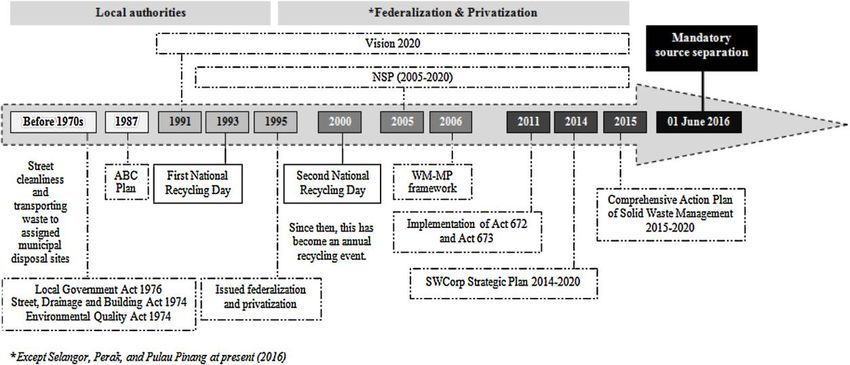
International Professional Doctoral Symposium 2019

 SANITARY LANDFILL IS A SOLUTION IN SOLID WASTE MANAGEMENT OR A SILENT
 THREAT TO ENVIRONMENT: MALAYSIAN SCENARIO

 Imran Ahmad1, Shreeshivadasan Chelliapan2, Norhayati Abdullah1 and Mohd Danish
 Ahmad3

 1Malaysia-Japan International Institute of Technology, Universiti Teknologi Malaysia, Jalan
 Sultan Yahya Petra, 54100, Kuala Lumpur, Malaysia
 2Razak Faculty of Technology and Informatics, Universiti Teknologi Malaysia, Jalan Sultan

 Yahya Petra, 54100, Kuala Lumpur, Malaysia
 3Student at Department of Post-Harvest Engineering and Technology, Aligarh Muslim

 University, Aligarh (UP) India.

Abstract: In Malaysia, the population is increasing at a rapid rate reaching 32.6 million in 2019.
This has resulted in a tremendous amount of solid wastes being generated which was
estimated as about 38,200 tons per day (1.12 kg/cap/day), in 2018 enough to fill the Twin
Towers every seven days. 82.5% of which is disposed of in landfills. If not managed properly
landfills can cause detrimental effects to environment, humans and aquatic world. Most of
the landfills in Malaysia are lagging with adequate facilities. This paper encompasses the
sections of history of solid waste management in Malaysia from 1970 to present, followed by
some alarming and dreadful cases of pollution due to ill management of landfills and lastly
some of the substantial measures to combat with the acute problem of solid waste focussing
on the responsibilities of government, manufacturer and user. Whether it be creating
awareness among people and implementing laws, 3R strategy or thinking before throwing
all play vial role in solid waste management. Collective and consistent effort is essential to
achieve Malaysia’s targeted recycling rate of 22% by 2020 and hence achieving Malaysian
vision with greater advancement towards a zero-waste nation.

Keywords: Solid Waste; Landfill; Leachate; Pollution; Recycling

1. Introduction

 The tremendous trend on the increasing of solid waste generation led to the potential
threat to the environment, society and economic losses as the dependence on the landfill
as the main disposal method which is particularly causing serious environmental problems
such as soil contamination, leachate, gas emission, and air pollution [1]. Proper solid waste
management present an opportunity not only to avoid the detrimental impacts associated
with waste, but it can recover resources, environment, economic, social benefits which
towards to the sustainable future. National development plans and solid waste
management plans in Malaysia are compiled (Figure 1) to provides a timeline of Malaysia’s
solid waste management from the late 1970s to the present.

 4
International Professional Doctoral Symposium 2019

 Figure 1. Solid Waste Management Policies and Plans Transformation in Malaysia [2]

1.1. Landfills

 Landfill is the most common MSW disposal method due to the simple disposal procedure,
low cost, and landscape-restoring effect. The primary objective of the landfill site design is to
provide effective control measures to prevent negative effects on surface water,
groundwater, soil and air. As a final dumping area for solid waste, the landfill is the most
efficient way to settle the collected waste.The classification of landfill sites in Malaysia with
their available facilities are summarised in table 1.In this section we will read about the
number of sanitary and non-sanitary landfills and their location.

 Table 1 Classification of landfill sites in Malaysia [2]
 Levels Available facilities
 I Controlled dumping Minimum infrastructure (fencing and
 perimeter drains)
 II Sanitary landfill with Class I facilities (with gas removal system,
 daily cover separate unloading and working area,
 daily cover and enclosing bund (divider
 constructed as the embankment of
 different waste cells)
 III Sanitary landfill with Class II facilities (with leachate
 leachate circulation recirculation system allowing the
 collection, recirculation and monitoring of
 landfill leachate)
 IV Sanitary landfill with Class III facilities (with leachate treatment
 leachate treatment system)

2. Waste management acts and regulations in Malaysia (historical background)

 Malaysia establishes the Action Plan for Beautiful and Clean (ABC Plan) country, a
management system for solid waste that includes every state of Malaysia. This plan brings
perks in enhancing Malaysia’s image as a beautiful and clean country. Moreover, this ABC
Plan is economically and environmentally friendly and should be easily accepted by the

 5
International Professional Doctoral Symposium 2019

community [3]. Under the supervision of Tun Dato Seri Dr Mahathir bin Mohamad as the 4th
Prime Minister the Sixth Malaysian Plan was introduced in 1991.

 He also structured Malaysia to come out with the Vision 2020, a vision that plans for the
nation by the year of 2020 to be a fully developed country. Respectively, the ABC Plan leads
to the recycling program first in the year 1993 and secondly in the year 2000. Started from
November 11, 2000, the National Recycling Day was proclaimed to be an annual event for
Malaysia. The recycling program encourages households to practice 3Rs habit, that comes
with the tagline “Think before you throw”. Later in this section it is discussed at length about
how privatisation came into existence and about the enforcement of different plans and
acts like NSP and Act 672 were formulated and enforced and the outcome of them.

3. Case studies at distinct locations directly or indirectly related to ill management of solid
waste disposal or landfills

3.1. Landfill pollutants leaching into sea [4]

 Fish farmers near Penang’s Pulau Burung sanitary landfill are blaming the facility for
emitting pollution that harms their cage-bred fish. There are about 150 fish farms, forming one
of the largest clusters of floating fish farms in Malaysia, and they are located 2km from
Penang’s only sanitary landfill. The fish farms produce 20,000 tonnes of fish yearly, including
for export to Singapore and Hong Kong. Fishermen are blaming the landfill for recent fish
deaths in their nets and cages and are accusing the landfill which is managed by the
Seberang Prai Municipal Council of illegally discharging leachate into the sea. Blackish water
was found flowing into the sea, believed to be leachate from the landfill. Shortly after that
tonnes of fish floated belly up in their cages. The fishermen want the department of
environment (DoE) and the fisheries department to conduct an urgent investigation into the
effects of the Pulau Burung landfill, which is located 6km northwest of Nibong Tebal, on the
coastal waters. It was reported at least 1,700 to 1,800 tonnes of rubbish is dumped at the
landfill on daily basis and at the time of rainfall, the drains are not able to contain the
leachate and it leaks out to the sea. If the bund was built using concrete, it could have held
back the leachate. This section incorporates many more case studies based on leachate
contamination, burning of solid waste at the landfill site, severe consequences related to
import of plastics, attitude and awareness of Malaysians to deal with solid waste, landfill
capacities and illegal dumping of solid waste in prime cities. We can understand about the
current Malaysian Scenario in solid waste management.

4.0 Substantial measures to be taken to control solid waste ill effects

4.1 Solid Waste Minimization through Recycling

 Recycling is one of the fundamental parts of the solid waste minimization plan which the
most desirable approach in reducing the amount of solid waste generation dumped in the
landfill [5]. However, to attain the recycling targets, the solid waste management essentially
requires an involvement from the local community as it largely depends on the household
awareness regarding the solid waste recycling issues rather than focused on the local
authority responsibility services [6]. This was followed by the role of government,
manufacturer and an individual in the recycling and overall solid waste management.

 6
International Professional Doctoral Symposium 2019

5.0 Conclusion

This paper provides brief introduction about the Malaysian history of solid waste
management policy and plan strategies to highlight the transformation of its policy and plan
strategies since the late 1970s to the present, followed by some alarming incidents reported
in different Malaysian areas with their detrimental effects to the environment and the people.
Lastly, we have incorporated substantial measures to minimize the solid waste.

References

[1] Agamuthu, P and Fauziah, S, H. 2011. Challenges and Issues In Moving Towards
Sustainable Landfilling In A Transitory Country – Malaysia, Waste Management and Research,
29 (1), 13-19.
[2] Moh, Y.C., and Manaf, L. A. 2017. Solid Waste Management Transformation And Future
Challenges Of Source Separation And Recycling Practice in Malaysia, Resources,
Conservation and Recycling, 116, 1–14.
[3] Ministry of Housing and Local Government. 2006. The Study of National Waste Minimization
in Malaysia Final Report. In cooperation with Japan International Cooperation Agency (JICA).
Retrieved from http://jpspn.kpkt.gov.my/
[4] Chern, L.T. 2019. Landfill pollutants leaching into sea, The Star Online, retrieved from
https://www.thestar.com.my/news/nation/2019/09/16/farmers-landfill-pollutants-leaching-
into-sea
[5] Dinie, M. and Don, M., M. 2013. Municipal Solid Waste Management in Malaysia: Current
Practices, Challenges and Prospect, Jurnal Teknologi (Sciences & Engineering) 62:1, 95–101.
[6] Keramitsoglou, K., M and Tsagarakis, K., P. 2013. Public Participation In Designing A
Recycling Scheme Towards Maximum Public Acceptance. Resources, Conservation and
Recycling, 70, 55-67.

 7
International Professional Doctoral Symposium 2019

 A FUZZY RULE-BASED FAILURE MODE, EFFECT AND CRITICAL ANALYSIS (FMECA) FOR
 CONTROL VALVE MAINTENANCE

 Faizal Abdullah and Mohd Khairi Abu Husain

 Razak Faculty of Technology and Informatics, Universiti Teknologi Malaysia, 54100 Kuala
 Lumpur, Malaysia

Abstract: Control valves are one of critical equipment in oil and gas process plant. Control
valve is highly engineered equipment, designed to very specific process parameters to serve
as final control element in a process control loop. Failure of control valve might lead to
catastrophic impact. Proper risk assessment is vital to optimized maintenance. This paper
presents application of failure mode, effect and critical analysis (FMECA) for control valve
using quantitative fuzzy based risks assessment. The main objective is to quantify the
qualitative values of the risk level for each failure modes using pre-determined inference rules.
The traditional FMECA RPN analysis is by multiplying three parameters: severity, probability
and detectability irrespective of the degree of importance of each input which might
produce similar value of RPN even the importance of the risk is different. A new method
called Fuzzy rule-based was proposed to be used in this research for the control valve FMECA.
Fuzzy RPN is utilized in order to identify highly critical failure mode as the focus of
maintenance strategy. The result of Fuzzy-RPN criticality analysis is significantly different
compare to traditional RPN. This due to Fuzzy-RPN utilized pre-defined expert rules, hence,
the RPN number produced is considered more reliable.

Keywords: Risk Assessment; Failure Mode, Effect and Critical Analysis; Fuzzy Rule-Based;
Process Control Valve; Process Plant.

1. Introduction

 Comprehensive and proactive maintenance is vital for control valve to prevent any risk
of a process plant. Risk analysis are one of the challenges of each maintenance activity.
There are number of methods available in industry standards and guidelines to analyze risk
in maintenance activities. Among these models, FMECA (Failure Mode Effect and Critical
Analysis) is one of the most common method used to analyze risk [1]. The traditional method
of FMECA determines the critical ranking of failure modes using the risk priority numbers
(RPNs), which is the product of evaluation criteria like the probability (P), severity (S) and
detection (D) of each failure mode. Traditional methods the FMECA have been considerably
criticized for a number of reasons. For example, it is not practical is some applications and
the result of RPN number is not represent the actual risk [2].
 The aim of this paper is to applied fuzzy rule-based failure mode, effect and critical
analysis as method of risk quantification for control valve. The idea is to calculate risk level or
RPN values for each identified failure modes and to determine the criticality ranking.

 8
International Professional Doctoral Symposium 2019

2. Methodology

 The overall step by step process of Fuzzy rule based FMECA process shown in Figure 3. First,
we define the input, which is the three parameters: Severity, Probability and Detectability.
The values of these three parameters are presented in the tables 2, 3 and 4. These tables
represent the crisp values of each parameter with the linguistic terms.

 Figure 1. Fuzzy FMECA flow diagram

2.1 Fuzzy FMECA RPN Method
 The probability, severity and detectability level determined by a set of crisp. The fuzzy sets
with failure probability ranking and the corresponding membership functions are shown in
Table 1, Table 2 and Table which is adapted from [1][3] and [4]. RPN is the result of the rating
of three parameters (Severity, Probability and Detectability). RPN gives direction to rank the
failure modes base on risk criticality.

 Table 1. Probability Level
 Probability Level
 Rank 1 2-3 4-6 7-8 9-10
 Linguist Very Low Modera High Very High
 ic Term Low te
 Criteria Failure Relatively Occasio Repea Failure is
 is Few nal ted almost
 Unlikel Failures Failures Failures inevitable
 y

 Table 2. Severity Level
 Severity Level
 Rank 1 2-3 4-6 7-8 9-10
 Linguistic Term Very Low Medi High Very
 Low um High
 Criteria (Impact on Minor Margin Major Catastro Disastr
 Safety, Financial & al phic ous
 Environmental)

 9
International Professional Doctoral Symposium 2019

 Table 3. Detectability Level
 Detectability Level
 Rank 1-2 3-5 6-8 9-10
 Linguistic Very High High Moderate Very Low
 Criteria Very high High Moderate Very low
 chance the chance the chance the chance the
 system will system will system will system will
 detect a detect a detect a detect a
 potential potential potential potential
 cause of cause of cause of cause of
 failure failure failure failure

 Table 4. Risk Priority Number Level
 Risk Priority Number
 Rank 100 200-300 400-600 700-800
 900 - 1000
 Linguistic Very Low Medium Very High High
 Term Low
 Criteria Minor Acceptable Undesirable Unacceptable Unacceptable
 (Non- (Non- (Critical) (Critical) (Very Critical)
 Critical) Critical)

 The RPN variable is determined using rules based on others previous research by [1], [5].
[6], and [7] as shown in Table 5.

 Table 5. Fuzzy RPN Rules
 Detectibility = Very High (Easily Detectable) Detectibility = Moderate (No Sign)
 Probability Probability
 Rule Very Very Rule Very Very
 Low Medium High Low Medium High
 Low High Low High
 VL VL VL VL VL VL VL L L L M M
 L VL VL VL L L L L L M M M
 Severity Severity
 M VL L M M M M L M M H H
 Level Level
 H L M M M H H M M H H H
 VH L M M H H VH M H H H VH
 Detectibility = High (Little Sign) Detectibility = Very Low (Impossible to Detect)
 Probability Probability
 Rule Very Very Rule Very Very
 Low Medium High Low Medium High
 Low High Low High
 VL VL VL L L L VL L L M M M
 L L L M M M L L M M M M
 Severity Severity
 M L M M M H M M M H H H
 Level Level
 H M M H H H H M H H VH VH
 VH M H H H H VH H H VH VH VH

3. Results and Discussions

3.1 Result
 The risk level (criticality) or RPN is calculated based on the established inference rules in
Table 6, from the three parameters (Probability, Severity, Detection). Table 6 populated the
result with comparison to the traditional RPN.

3.2 Discussion

 Based on the criticality analysis of the failure modes, risk priority number was calculated
and the output results from both the traditional RPN and the fuzzy RPN method are presented
in in Table 8. From the table, the risk level calculation of traditional RPN give the result based
on multiplying the probability, severity and detectability numbers whereas the fuzzy RPN

 10
International Professional Doctoral Symposium 2019

method gives values that are determined in by the inferences rules that was defined. From
the result, the significant risk level different produced by both methods.

 Table 6. Fuzzy RPN result compare to traditional RPN
 Failure P S D Conventional Criticality FRPN Criticality
 Mode RPN Number
 (PxSxD)
 FM1 7 4 8 224 Low 850 High
 FM2 6 3 3 54 Very Low 650 Medium
 FM3 1 5 5 25 Very Low 330 Low
 FM4 8 8 4 256 Low 820 High
 FM5 3 8 4 96 Very Low 620 Medium
 FM6 2 10 9 180 Low 820 High

4. Conclusion

 The obtained results confirm its applicability of the fuzzy RPN where the result of the
criticality is significantly different with the traditional RPN. This is due to the fuzzy RPN model
incorporates linguistic variables as input values and returns a result that was predetermined
in inference rules. The result of the fuzzy RPN shows better criticality risk level compared to
traditional RPN.

Acknowledgement

I would like to thank my committed supervisor, Dr Mohd Khairi Abu Husain for encouraging
me to start writing my research, for his guidance, advice and motivation.

References

[1] Liu, H.-C., Liu, L., & Liu, N. (2013). Risk evaluation approaches in failure mode and effects
 analysis: A literature review. Expert systems with applications, 40(2), 828-838.
[2] Gupta, G., & Mishra, R. (2017). A failure mode effect and criticality analysis of
 conventional milling machine using fuzzy logic: Case study of RCM. Quality and
 reliability engineering international, 33(2), 347-356.
[3] Bowles, J. B., & Peláez, C. E. (1995). Fuzzy logic prioritization of failures in a system failure
 mode, effects and criticality analysis. Reliability engineering & system safety, 50(2), 203-
 213.
[4] IEC60812. (2006). IEC 60812: Analysis techniques for system reliability-Procedure for
 failure mode and effects analysis (FMEA). Geneva, Switzerland: International
 Electrotechnical Commission, 1-93.
[5] Gallab, M., Bouloiz, H., Alaoui, Y. L., & Tkiouat, M. (2019). Risk Assessment of Maintenance
 activities using Fuzzy Logic. Procedia Computer Science, 148, 226-235.
[6] Balaraju, J., Raj, M. G., & Murthy, C. S. (2019). Fuzzy-FMEA Risk Evaluation Approach for
 LHD Machine-A Case Study. Journal of Sustainable Mining.
[7] Jaderi, F., Ibrahim, Z. Z., & Zahiri, M. R. (2019). Criticality analysis of petrochemical assets
 using risk-based maintenance and the fuzzy inference system. Process Safety and
 Environmental Protection, 121, 312-325.

 11
International Professional Doctoral Symposium 2019

 OPTIMIZATION OF SOIL-NAILED WALL DESIGN USING SLOPE/W SOFTWARE

 Mohd Sukry Mohamed, Fathiyah Hakim Sagitaningrum and Samira Albati Kamaruddin

 Razak Faculty of Technology and Informatics, Universiti Teknologi Malaysia, 54100 UTM
 Kuala Lumpur, Kuala Lumpur, Malaysia

Abstract: Optimization of soil-nailed wall design can be done with adjustment on parameters
and the construction elements during the design analysis. As there are many criteria in soil
nailing design that could be optimized, this paper focused on three main parameters: length,
inclination, and spacing of the soil nail. The aim of this paper is to evaluate the three
parameters optimization reanalyses and their cost difference from the original design. The
data were collected from a project in Selangor area and were reanalysed using the
Morgenstern-Price Method analysis from a Limit Equilibrium software (SLOPE/W). The
optimization re-analysis was evaluated with the change of the Factor of Safety (FOS) value
for all cases. Results showed that reducing the soil nail length will reduce the FOS, reducing
the soil nail inclination will increase the FOS, and reducing the soil nail spacing will increase
the FOS. It was also known that the cost reduces from 18% to 53% in the reanalysis which
showed that optimization design should be considered in all consultant firms and can be
used by the clients as verification for future soil-nailed wall design.

Keywords: Cost-Effective Design; Limit Equilibrium Method; Optimization; Soil-nailed Wall;
SLOPE/W.

1. Introduction

 There are at least three parameters of soil nailing that would affect the slope stability
design and Factor of Safety (FOS). The parameters taken into consideration are soil nail
inclination, spacing, and length. This finding was supported by Rawat (2018) who observed
that increasing the inclination angle of soil nailing would reduce the FOS. Another study by
Gunawan et al (2017) stated that the FOS of a slope would increase with the increase of the
length of nails in a soil nailing system. Lastly, research by A. Mohamed (2010) stated that the
increase in the ratio of nail length with wall height would eventually increase the FOS. He also
found that nail inclination had a lesser effect on the FOS, whereas the decrease of nail
spacing would eventually increase the FOS. In this study, a project in the Selangor area
constructed a soil-nailed wall system, which was then known that it doesn’t have an
optimized design that led to an ineffective construction cost. From the three parameters
stated earlier, this study will then evaluate the three parameters with optimization reanalyses
and their cost difference from the original design. This optimized design could then be a
benchmark for clients in order to verify future soil-nailed wall designs.

2. Methodology

 In order to evaluate the effect of soil nail inclination, spacing, and length for soil-nailed
wall optimized design, a reanalysis was done with various cases from the original design. The
reanalyses were done with evaluating the FOS of both the initial and optimized design slope
using a Limit Equilibrium Method (LEM) software, SLOPE/W from Geostudio 2012 with the
general method of slices developed, Morgenstern-Price Method (M-P). The analyses were

 12
International Professional Doctoral Symposium 2019

done according to the JKR guidelines and were assured to not exceed the FOS limits. The
parameters of nails length, nails spacing and nails inclination were modified for each case,
resulting from a trial and error for each case variable until the FOS was found to be near the
limit but not yet exceeded. Once the FOS for the five cases were determined. Cost estimation
for each of the cases was calculated in order to know the cost-effectiveness of each case
compared to the initial design cost. The cost estimation for each case was done with a simple
Microsoft Excel tabulation with the Bill of Quantity (BOQ) of the project modelled as the main
data.

3. Reanalyses and Factor of Safety Results

3.1 Slope Stability Analyses
 The modelled design example for one of the cases that include the elevation of the
berms, nail inclination, and nail length of the slope before reanalyses can be seen in Figure
2. From all the cases, it was known at the end that the initial FOS was higher compared to
the results from the reanalyses and adjustments. The FOS for all cases before reanalyses were
known to be 1.997, 1.952, 1.813 1.648 and 1.585 whereas, after the reanalyses, the FOS were
known to be 1.501, 1.512, 1.523, 1.505 and 1.554.

 Factor of Safety vs. Lambda (Case 3)
 1.54

 1.52

 1.5
 Factor of Safety

 1.48

 1.46

 1.44

 1.42

 1.4

 1.38
 -0.1 0 0.1 0.2 0.3 0.4 0.5 0.6
 Lambda

 Figure 1. Elevation soil nailing design and FOS 1.523 for Case 3

 13
International Professional Doctoral Symposium 2019

3.2 Optimized Parameters and Rate
 From all the cases, the selected nail inclination ranges from 100 to 250, nail spacing from
1.0 to 1.8 meters (m) and nail length from 3 to 15 m. Referring to Table 1, the behaviour of
each case differs according to the change of the three selected parameters: soil nail
inclination, the spacing between soil nails, and length of the nail.

 Table 1. Parameters and nails rate for all cases
 Case Reanalyses Nail Nail Tensile Bond Nail Factor Nails Rate
 No. inclination Spacing Capacity Diameter Length of (RM)
 (degrees) (m) (KN) (m) (m) Safety
 1 Before 15 1.5 322 0.125 6&9 1.997 410, 495
 After 20 2.0 322 0.125 3, 6 & 9 1.501 205, 410, 495
 2 Before 25 1.0 322 0.125 12 1.952 710
 After 20 1.5 322 0.125 6 & 12 1.512 410, 710
 3 Before 15 1.0 196 0.125 12 1.813 710
 After 20 1.5 196 0.125 9 1.523 495
 4 Before 10 1.5 322 0.125 12 & 15 1.684 710, 910
 After 20 1.2 322 0.125 9 1.505 495
 5 Before 10 1.5 & 1.0 322 0.125 12 & 9 1.585 495, 710
 After 15 1.8 322 0.125 12 1.554 710

3.3 Cost Reduction
 From the reanalyses in the previous section, it can be seen that all of the cases showed
a similar behaviour where the reduced FOS would eventually reduce the cost. Hence, it
could be concluded that optimizing the soil-nailed wall design would result in a more cost-
effective design.

 Before reanalysis After reanalysis

 RM1,600,000 RM1,363,200
 RM1,400,000
 RM1,200,000
 RM1,000,000
 RM714,960
 Cost

 RM738,400
 RM800,000 RM635,580
 RM601,313
 RM600,000 RM285,458
 RM400,000 RM491,636
 RM389,760 RM423,720
 RM200,000
 RM0 RM189,533
 1 2 3 4 5
 Case Number

 Figure 2. Cost reduction before and after reanalyses

 According to Table 2 that described the change of FOS from the optimization of
design, the value of the optimized design was found to be lower than the initial FOS.

 14
International Professional Doctoral Symposium 2019

 Table 2. Cost-saving and percentage saving

 Before Reanalyses After Reanalyses
 Case Factor of Cost (RM) Factor of Cost (RM) Cost Saving Percentage
 No. Safety Safety (RM) saving (%)
 1 1.997 RM285,458.33 1.501 RM189,532.50 RM95,925.83 33.60
 2 1.952 RM738,400.00 1.512 RM389,760.00 RM348,640.00 47.22
 3 1.813 RM1,363,200.00 1.523 RM635,580.00 RM727,620.00 53.38
 4 1.684 RM714,960.00 1.505 RM423,720.00 RM291,240.00 40.74
 5 1.585 RM601,313.33 1.554 RM491,635.56 RM109,677.78 18.24

4. Conclusion
 The optimum factors considered for the three design variables: the length of a soil nailing,
the spacing of soil nailing, and the inclination of the nail. These three design variables were
adjusted through a method of trial and error until the optimized design within the permissible
limits were achieved. The length of soil nailing was the largest affecting factor in optimizing
the design, whereas the inclination of the soil nailing was the least affecting factor. It can be
concluded that reducing the length of soil nailing would reduce the FOS, reducing the nail
inclination would increase the FOS, and reducing the spacing between soil nailing would
increase the FOS.

Acknowledgement
The first author is an Engineering Doctorate student who is partially supported by the Ministry
of Higher Education (Malaysia). The second author is a PhD student who is partially supported
by the International Doctoral Fellowship from Universiti Teknologi Malaysia (UTM)

References

[1] A.Mohamed (2010). Design Charts for Soil Nailing. Master of Science in Civil Engineering,
 Shobra Benha University, Cairo Dewedree, S., & Jusoh, S. N. (2019). Slope stability
 analysis under different soil nailing parameters using the SLOPE/W software. Journal of
 Physics: Conference Series, 1174(1). doi:10.1088/1742-6596/1174/1/012008.
[2] Geoguide 7 (2008), Guide to Soil Nail Design and Construction, Geotechnical of
 Engineering Office the Government of Hong Kong vol. 7, pp. 81.
[3] GEO-SLOPE International Ltd (2012). Stability Modelling with SLOPE/W. An Engineering
 Methodology, 6th Ave SW Calgary, Alberta, Canada Ghareh, S. (2015). Parametric
 assessment of soil-nailing retaining structures in cohesive and cohesionless soils.
 Measurement, 73, 341-351. doi:http://dx.doi.org/10.1016/j.measurement.2015.05.043.
[4] Gunawan, I., Surjandari, N. S., & Purwana, Y. M. (2017). The study on length and
 diameter ratio of nail as a preliminary design for slope stabilization. Journal of Physics:
 Conference Series, 909(1). doi:10.1088/1742-6596/909/1/012073.
[5] Rawat, P., & Chatterjee, K. (2018). Seismic Stability Analysis of Soil Slopes Using Soil Nails.
 Geotechnical Special Publication, 2018-June (GSP 293), 79 - 87.
 doi:10.1061/9780784481486.009.

 15
International Professional Doctoral Symposium 2019

 MICROSTRUCTURAL TRANSFORMATION BY COMPOSITIONAL MODIFICATION OF Ti-
 6Al-4V ALLOY FOR AEROSPACE APPLICATIONS

 Astuty Amrin1, Ayad Omran Abdalla2, Meysam Toozandehjani1 and Noorlizawati Abdul
 Rahim1

 1Razak Faculty of Technology and Informatics, Universiti Teknologi Malaysia Kuala Lumpur,
 54100, Kuala Lumpur, Malaysia
 2College of Mechanical Engineering Technology, Alrahba Street, Alfwayhat, Benghazi,

 Libya

Abstract: Ti-6Al-4V alloy has been extensively used in aircraft for lightweight structural
applications including wings and fuselage. Similar to other Ti alloys, however, its major
drawback is higher cost leading to limitation in its application. In this case, Iron (Fe) has been
introduced to Ti-alloys as a replacement of expensive element like vanadium (V) and
molybdenum (Mo) in order to lower cost. In this work, a new Ti-6Al-Fe alloy was developed
through major composition modifications of Ti–6Al–4V alloy. The vanadium element in Ti–6Al–
4V alloy was replaced by 1 to 3 wt.% Fe. It was found that Fe can be effectively act as a β-
stabilizing element. Ti-6Al-Fe system bring a strong advantage over conventional Ti-6Al-4V
alloy in many aerospace applications owing to outstanding mechanical and corrosion
properties.

Keywords: Ti-6Al-4V Alloy; Iron (Fe); Microstructure; Mechanical Response, Aerospace

1. Introduction

 Dual phase (α+β) Ti-6Al-4V alloy is definitely one of the most extensively used Ti alloys in
aircraft, where it has been commonly utilised as a structural material, airframes and engine
components [1-3]. The mechanical response of Ti-6Al-4V alloy can be easily modified and
coherently affected by adding alloying elements or altering its composition. However, this
alloy is expensive because of the expensive alloying elements such as vanadium (V). To lower
material cost and improve properties, researchers have introduced the cheaper alloying
elements as an alternative of more expensive elements. Addition of alloying elements has
direct influence on microstructures that would positively reflect on mechanical response of
these alloys leading to significant improvements [4-7]. Of the interest of authors, Fe can be
an attractive alloying element in (α+β) Ti-6Al-4V alloy as a potential β-stabilizers. It can be as
a substitution to expensive β-stabilizing V element in order to lower alloy cost and
simultaneously improve mechanical response [5-7]. Therefore, a new Ti-6Al-xFe alloy (x=1, 2,
and 3 wt.%) was developed in this study by compositional modification of of Ti-6Al-V alloy. In
this regards, V as an expensive alloying element was replaced by Fe as a cost-effective β-
stabilizing alloying element in Ti-6Al-4V alloy. Then, the effect of addition of Fe on the
microstructures, mechanical and corrosion response of developed Ti-6Al-(1-3)Fe alloy was
studied.

2. Materials and Methods

 Ti-6Al-(1-3)Fe alloys containing up to 3 weight percentage (wt.%) were supplied from TIMET
Co. Alloys were initially manufactured by melting in a vacuum arc melting technique using

 16
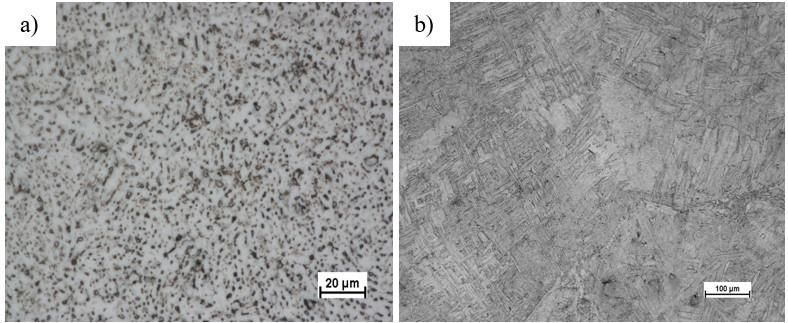
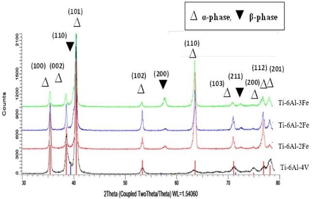
International Professional Doctoral Symposium 2019

tungsten electrode. The as-received alloys were formed into bar shaped samples. Then,
samples were heated above β-transus temperature at 1038 °C. Finally, samples underwent
rolling process to obtain 35% thickness reduction where final dimensions of 160× 60 × 6 mm
was obtained.
 An X–ray Diffractometer (XRD), BRUKER-D8 equipped with a 1-D (LYNXEYE) fast detector
was used to record the XRD pattern of the investigated alloys. The morphological and
microstructural features of Ti-6Al-(1-3)Fe were observed using optical microscope (NIKON
Eclipse). The micro-hardness of Ti-6Al-(1-3)Fe alloys were measured using a digital Micro-
Vickers hardness tester (WOLPERT–Model: 401MVD). Three different measurements was
carried out at a load of 1 kgf and a dwell time of 10 seconds on the randomly selected
positions of each specimen and the average value was reported. Tensile tests were carried
out using a 50 KN universal tensile testing machine (SHIMADZU). Electrochemical test
measurements were carried out using standard three-electrode system at room using
AutoLab PGSTAT128N potentiostat supported with Nova 1.11 software programme. Silver
chloride electrode (Ag/AgCl) was used as reference electrode while platinum (Pt) wire was
the counter electrode. A 3.5% NaCl solution was prepared as an electrolyte solution.

3. Results and Discussions

 Figure 1 illustrates the microstructure of Ti-6Al-4V and Ti-6Al-1Fe alloys. Optical micrographs
reveals the fully equiaxed microstructure of Ti-6Al-4V alloy which is composed of a uniform
structure of α grains and grain boundaries of β (Figue 1a). The microstructures of Ti-6Al-(1-3)Fe
alloys consist of as a basket weave-like structure which is well known as a typical fully lamellar
microstructure as also reported earlier [7]. For instance, the microstructure of Ti-6Al-1Fe alloy
is illustrated in Figure 1b. By increasing Fe content, the lamellar colony size and the α-lamella
width decreases from 780 µm to 457 µm and from 2.65 µm to less than 1 µm, respectively.

 Figure 1. The optical micrograph of a) Ti-6Al-4V and b) Ti-6Al-1Fe alloys

 Figure 2 shows XRD pattern of Ti-6Al-4V and Ti-6Al-(1-3)Fe alloys. The XRD patterns reveal
that Ti-6Al-(1-3)Fe alloys are clearly dual phases that consist of coexistent α and β-phases.

 17
International Professional Doctoral Symposium 2019

 Figure 2. XRD patterns of Ti-6Al-4V and Ti-6Al-(1-3)Fe alloys.

 The percentages of α and β phases in Ti-6Al-(1-3)Fe alloys are listed in Table 1. Obviously,
the percentage of β-phase increases by increasing Fe content. Fe as a β-phase stabilizing
alloying element effectively reduces the β-transus temperature, then the formation of β-
phase is consequently enhanced [8]. In addition, TiFe intermetallic compounds such as
Ilmenite (FeTiO3) and Rutile (TiO2) did not detected as existing phases in Ti-6Al-(1-3)Fe alloys
indicating that Fe is a strong β-stabilizer that can suppress TiFe formation.

 Table 1. The percentage of α and β phases in Ti-6Al-(1-3)Fe alloys.

 Phase Percentage (%) Increment percentage
 Specimen
 α β of β-Phase (%)
 Ti-6Al-4V 95.2 4.8 0
 Ti-6Al-1Fe 91.9 8.1 68.8
 Ti-6Al-2Fe 89.6 10.4 116.67
 Ti-6Al-3Fe 86.9 13.1 172.9

 The physical and mechanical properties of Ti-6Al-(1-3)Fe alloys is tabulated in Table 2. The
density values in Ti-6Al-(1-3)Fe alloys increase as Fe content increases. It can be due to higher
density of Fe element compared to other composing element such as Ti, Al, and V. Ti-6Al-(1-
3)Fe alloys have higher micro-hardness (HV) and ultimate tensile strength (UTS) but lower
ductility (%) than Ti-6Al-4V alloy. In addition, HV, UTS and elongation % values increase by
increasing Fe content.

 Table 2. The physical, mechanical and corrosion properties of Ti-6Al-(1-3)Fe alloys.

 Density UTS Elongation Corrosion Rate
 Specimen HV
 (g/cm3) (MPa) (%) (mm/year) * 10-5
 Ti-6Al-4V 4.374 302 833 12.5 2.10
 Ti-6Al-1Fe 4.338 327 897 11.3 1.77
 Ti-6Al-2Fe 4.369 338 974 10.4 2.09
 Ti-6Al-3Fe 4.386 370 1069 8.1 2.29

 The higher mechanical response of Ti-6Al-(1-3)Fe alloys is attributed to the fine lamellar
microstructure. Ti-6Al-1Fe shows excellent corrosion resistance of 1.77E-5 mm/year, the lowest

 18
International Professional Doctoral Symposium 2019

corrosion rate in 3.5% NaCl solution, while higher corrosion rate of 2.1E-5 mm/y was recorded
by its counterpart, Ti-6Al-4V alloy.

4. Conclusion

 The compositional modifications of Ti-6Al-4V alloy through replacement of V element by
Fe was carried out and resulted in the improvement of density, strength, hardness as well as
corrosion resistance of Ti-6Al-(1-3)Fe alloys compared to Ti-6A-4V alloy. These enhancement
in the mechanical and corrosion resistance of Ti-6Al-(1-3)Fe alloys is attributed to the
developed bi-modal α+β microstructure which contain a very fine lamellar α+β
microstructure wherein size of lamellar colonies and the lamellae width gradually decrease
by increasing Fe content.

Acknowledgement

Authors would like to acknowledge Assoc. Prof. Dr. Khairur Rijal in providing the furnace for
the experimental work and all UPMU technicians for their technical support.

References

[1] Lütjering, G. and Williams, J. C. 2007. Titanium, Springer.
[2] Whittaker, M. 2015. Titanium Alloys. Metals, 5, 1437-1439.
[3] Wang, S. Q., Liu, J. H. and Chen, D. L. 2013. Strain-controlled fatigue properties of
 dissimilar welded joints between Ti-6Al-4V and Ti17 alloys. Materials and Design, 49, 716-
 727.
[4] Liang, Z., Miao, J., Brown, T., Sachdev, A. K., Williams, J. C. and Luo, A. A. 2018. Low-cost
 and high-strength Ti-Al-Fe-based cast titanium alloy for structural applications. Scripta
 Materialia, 157, 124–128.
[5] Kadiri, H., Wang, L., Ozkan Gulsoy, H., Suri, P., Park, S., Hammi, Y. and German. R, 2009.
 Development of a Ti-based alloy: design and experiment. The Journal of the Minerals,
 Metals and Materials Society (JOM), 61, 60-66.
[6] Hideki, F. and Kazuhiro, T. 2002. Development of high performance Ti-Fe-Al alloy series.
 Nippon Steel Technical Report, 113-117.
[7] Abdalla, A. O., Amrin, A., Muhammad, S. and Hanim M. A. A. 2017. Microstructures and
 hardness of newly designed Ti-6Al-(1-3)Fe alloys. Applied Mechanics and Materials, 864,
 142-146.
[8] Joshi, V. A. 2006. Titanium alloys: An atlas of structures and fracture features, Taylor and
 Francis.

 19
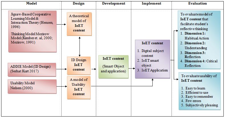
International Professional Doctoral Symposium 2019

 A CONCEPTUAL FRAMEWORK FOR INTERNET OF EDUCATIONAL THINGS (IoET)

 Salbiah Zainal, Rasimah Che Mohd Yusoff and Hafiza Abas

 Razak Faculty of Technology and Informatics, Universiti Teknologi Malaysia, 54100 Kuala
 Lumpur, Malaysia

Abstract: The paper aims to identify a conceptual framework for Internet of Educational
Things (IoET) system design that facilitates students’ reflective thinking. Literature review has
been used to identify the components of the conceptual framework. This IoET conceptual
framework consists of five essential elements: theoretical model, instructional design model,
development life cycle, implementation and evaluation. The Jigsaw-Based Cooperative
Learning model and Interaction theory, and Mezirow reflective thinking model has been
used as the theoretical foundation to develop the instructional design. For the prototype
development life cycle, ADDIE model will be used. Prototype of IoET will be evaluated using
usability evaluation and enhancement on students’ reflective thinking. With implementation
of IoET system in the teaching and learning of process making will then leads to a deeper
understanding in learning.

Keywords: Internet of Educational Things, Theoretical Model, Reflective Thinking, Students’,
Conceptual Framework.

1. Introduction

 The fourth Industrial Revolution (IR 4.0) has changed the landscape of educational
innovation. Internet of Things (IoT) is one of the domains enabling technology in IR 4.0.
Gartner, 2016 estimated that 5.5 million new “things” are connected to networks and nearly
21 billion devices will be connected with Internet of Things (IoT) by 2020. IoT is swiftly
expanding beyond devices for schools. The key advantages of IoT technology in such cases
are to make the learning process more “real, local and fun”, allowing students to understand
more complex concepts by making use of relevant information obtained from interaction
with physical objects in the real world.
 Internet of Education Things (IoET) can be defined as emerging technology integrated
with smart object and is felt many expect of education such as course presentations, sharing
knowledge and ideas, personalized content and learning activities (Bagheri et al., 2016). IoET
are flexible, allow hyper-connectivity between physical and virtual objects, adaptable,
accessible and scalable which becomes properties of the IoT (Abbasy et al., 2017). There
are many potential of IoET based learning platform to be implemented such as smart
classroom (Veeramanickam et al, 2016), smart attendance system (Chan, 2017), smart
monitoring student (Megalan, 2018; Pushpa, 2014). The characteristic of 21st century learners
indicates that students should be innovators, creators, flexible and critical thinkers. Student-
centred learning is a best practice in provoke to 21st-century learning experiences. For
Science, Technology, Engineering and Mathematics (STEM) subject, IoET can be used to
enhance teaching and learning especially for digital natives students. 21st century learning
should able to provoke critical thinking, communicating and collaborating using technology
(Higgins, 2014). However there are lack of the design of IoT for teaching and meaning to
provoke reflective thinking as part of critical thinking. This study aims to identify a conceptual
framework for IoET system design that facilitate students’ reflective thinking

 20
You can also read