PCell Wireless Reinvented - An Introduction to pCell
←
→
Page content transcription
If your browser does not render page correctly, please read the page content below

pCell
Wireless Reinvented

An Introduction to pCell
White Paper, February 2015

Steve Perlman                Antonio Forenza, PhD
Founder & CEO                Co-Founder & Principal Scientist

Artemis Networks LLC                              www.artemis.com
ARTEMIS NETWORKS WHITE PAPER
February 2015

An Introduction to pCell
pCell is a revolutionary new approach to wireless, dramatically increasing the
spectral efficiency of LTE and Wi-Fi systems, while remaining compatible with
standard LTE and Wi-Fi devices. This White Paper describes pCell technology in
detail, including vision, history, architecture, applications, performance and
comparison to conventional wireless technologies.

To contact Artemis Networks, please visit www.artemis.com.

U.S. patents 7,418,053, 7,451,839, 7,599,420, 7,633,994, 7,636,381, 7,711,030, 7,885,354,
8,160,121, 8,170,081, 8,307,922, 8,428,162, 8,469,122, 8,542,763, 8,571,086, 8,654,815,
8,971,380, international patents, patents pending. pCell, pWave, Artemis and the Artemis logo
are trademarks of Artemis Networks LLC.

Copyright © 2015, Artemis Networks, LLC. All Rights Reserved.

An Introduction to pCell          Patents, Patents Pending                                 2
ARTEMIS NETWORKS WHITE PAPER
February 2015
Table of Contents
1 pCELL: 5G Now......................................................................................................................... 6
2 Background .............................................................................................................................. 8
2.1 pCell: Meeting 5G requirements today, in compliance with 4G devices....................... 11
3 The Limits of Cellular Architecture ........................................................................................ 13
3.1 Inconsistent data rates ................................................................................................... 13
3.2 The limits of cellular micro-diversity .............................................................................. 16
3.3 The limits of cellular macro-diversity ............................................................................. 20
3.3.1 Small-cells and inter-cell interference coordination .............................................. 21
3.3.2 Network MIMO and CoMP ..................................................................................... 22
3.4 Other limitations of cellular systems ............................................................................. 22
3.4.1 3D environments..................................................................................................... 22
3.4.2 Crisis situations ....................................................................................................... 23
3.4.3 Security vulnerabilities ............................................................................................ 24
3.4.4 Millimeter wave performance in cellular networks ............................................... 25
3.5 Summary: Cellular architecture has reached capacity and reliability limits .................. 26
4 pCell Technology.................................................................................................................... 27
4.1 Uniform coverage........................................................................................................... 28
4.2 Consistent data rate ....................................................................................................... 30
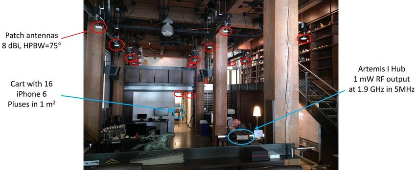
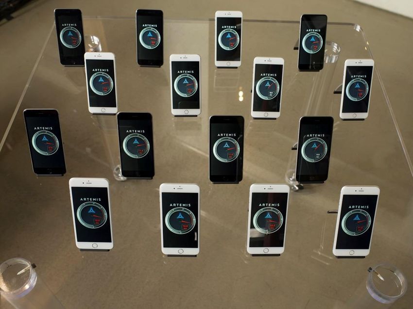
4.3 Indoor field trials ............................................................................................................ 34
4.3.1 pCell and cellular performance compared ............................................................. 36
4.3.1.1 Performance with 2 or 4 network antennas ................................................... 36
4.3.1.2 Performance with increasing numbers of user devices .................................. 38
4.3.1.3 Performance with more user devices than network antennas ....................... 40
4.3.2 pCell SE consistency ................................................................................................ 42
4.4 Outdoor performance .................................................................................................... 42
4.4.1 Hexagonal and arbitrary layouts ............................................................................. 43
An Introduction to pCell Patents, Patents Pending 3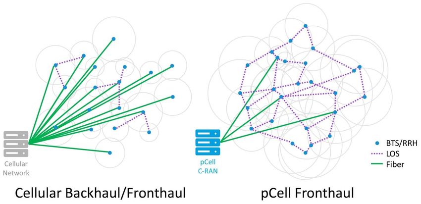
ARTEMIS NETWORKS WHITE PAPER
February 2015

      4.4.2        256-QAM performance ........................................................................................... 45
    4.5     pCell vs. Cellular ............................................................................................................. 47
    4.6     pCell ubiquitous connectivity ......................................................................................... 47
5     pCell Deployment .................................................................................................................. 49
    5.1     pCell compatibility with current standard mobile devices ............................................ 49
      5.1.1        pCell LTE .................................................................................................................. 49
      5.1.2        pCell Wi-Fi ............................................................................................................... 49
      5.1.3        Voice support and internet connectivity ................................................................ 50
    5.2     pCell Cloud-RAN architecture ........................................................................................ 50
      5.2.1        Traversing adjacent pCell Cloud-RANs.................................................................... 53
      5.2.2        Hand-off to adjacent cellular networks .................................................................. 53
    5.3     pCell software-defined radio (SDR) architecture ........................................................... 54
      5.3.1        pCell CPU architecture ............................................................................................ 54
      5.3.2        pCell virtual radio instances (VRIs) ......................................................................... 55
    5.4     pCell infrastructure and fronthaul ................................................................................. 60
      5.4.1        Cellular infrastructure is expensive to deploy and operate ................................... 60
      5.4.2        pCell infrastructure is inexpensive to deploy and operate..................................... 60
      5.4.3        pCell fronthaul data rate comparable to cellular backhaul data rate .................... 62
    5.5     pCell radio deployment options ..................................................................................... 64
      5.5.1        pWave remote radio heads .................................................................................... 65
      5.5.2        Artemis Hubs........................................................................................................... 65
      5.5.3        pCell radio synchronization .................................................................................... 66
6     pCell Technologies and Features ........................................................................................... 68
    6.1     Exploiting wireless propagation effects ......................................................................... 68
      6.1.1        Space selectivity ...................................................................................................... 68
      6.1.2        RF interference ....................................................................................................... 69
    6.2     Channel state information ............................................................................................. 69
    6.3     pCell clusters .................................................................................................................. 71

An Introduction to pCell                            Patents, Patents Pending                                                                    4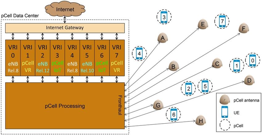
ARTEMIS NETWORKS WHITE PAPER
February 2015

    6.4     User mobility .................................................................................................................. 75
    6.5     3D propagation............................................................................................................... 76
    6.6     Location positioning ....................................................................................................... 76
    6.7     Crisis support .................................................................................................................. 78
    6.8     Physical data security ..................................................................................................... 79
7     Future pCell Applications....................................................................................................... 81
    7.1     256-QAM support .......................................................................................................... 81
    7.2     pCell compatibility with specialized wireless devices .................................................... 81
      7.2.1        pCell VR ................................................................................................................... 82
      7.2.2        pCell IoT .................................................................................................................. 85
8     Acknowledgments ................................................................................................................. 86
9     Endnotes ................................................................................................................................ 87

An Introduction to pCell                             Patents, Patents Pending                                                                   5
ARTEMIS NETWORKS WHITE PAPER
February 2015
1 pCELL: 5G Now
Artemis™ pCell™ technology is a radical new approach to wireless that increases the capacity of
LTE and Wi-Fi networks by over an order of magnitude, while dramatically improving Quality of
Service (QoS) and maintaining off-the-shelf compatibility with unmodified LTE and Wi-Fi
devices, such as iPhone, iPad and Android devices. pCell meets proposed 5G performance
targets today, while remaining compatible with 4G devices.
pCell technology accomplishes this through an entirely new approach to wireless: rather than
avoiding interference like cellular or Wi-Fi systems, pCell embraces interference, utilizing
interfering transmissions to synthesize a tiny personal cell, a “pCell”, around each individual
user device, enabling every user to utilize the full capacity of the spectrum at once. Instead of
many users sharing the limited capacity of one cell, resulting in steadily declining data rates as
new subscribers join the network, with pCell technology, each user gets a personal cell. So, no
matter how many users are sharing the same spectrum, each user is able to experience the full
capacity of the spectrum concurrently with other users.
pCell has a wide range of advantages over conventional wireless technologies:
Leapfrog in spectral efficiency. LTE networks today achieve a spectral efficiency (SE)1 of
1.7 bps/Hz2. Practical pCell systems today achieve average spectral efficiency of 59
bps/Hz, a 35X leapfrog with unmodified standard LTE devices, such as iPhone 6/6 Plus,
iPad Air 2 and Android devices, as well as Wi-Fi devices. pCell’s spectral efficiency scales
indefinitely, while remaining compatible with legacy devices.
Consistent, reliable data rate. Cellular or Wi-Fi data rate drops off rapidly from cell
center (e.g. 100 Mbps) to cell edge (e.g. 1 Mbps), resulting in highly variable and
unreliable service quality. With pCell the data rate remains uniformly near peak
throughout the coverage area, including vertically in tall buildings, enabling QoS service
offerings, such as 4K UHD video.
Low deployment, operations cost. Cellular radios must be carefully placed in specific
locations within a “cell plan” (reconfigurable by SON3 or not) with antennas carefully
aimed to avoid interference and dead zones. pCell deployment is fast with minimal real-
estate and fronthaul costs because inexpensive pWave™ radio heads can be placed
anywhere in the coverage area, allowing carriers to choose low-cost real estate
locations that have line-of-sight (or low-cost fiber) paths for fronthaul.
An Introduction to pCell Patents, Patents Pending 6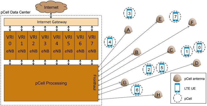
ARTEMIS NETWORKS WHITE PAPER
February 2015
Easily scalable capacity. Adding radios to a cellular system to increase capacity requires
complex and precise placement so as not to interfere with the existing cell plan. pCell
capacity scales easily by simply adding new pWave radio heads into the coverage area
wherever it is inexpensive and convenient. Each added pWave increases the aggregate
data capacity of the pCell system.
Highly robust for public safety. During a crisis, if a cell tower is disabled, or if there is a
surge in demand that overwhelms the cell, mobile service in the coverage area of the
tower will be unavailable. With pCell, many pWave antennas overlap throughout the
coverage area, so even if several pWave antennas are disabled or if there is a sudden
surge in demand, mobile service is maintained.
Physically secure communications. Since cellular transmissions can be received from
anywhere within the coverage area, anyone who gains access to the cryptographic keys
can intercept communications4. With pCell, the transmitted data only physically exists
at the point of reception, providing physically secure communications.
Lower power consumption at the user device. Uplink signals are received by many
pWave antennas at once, enabling user devices to transmit at lower power and save
battery life.
Lower cost user devices. While pCell is compatible with unmodified standard LTE
devices, the same pCell infrastructure simultaneously supports far lower cost and lower
power user devices utilizing pCell-optimized protocols in the same spectrum as LTE,
enabling carriers to offer far lower cost entry points and support “Internet of Things”.
Low latency cloud hosting. Under heavy load, pCell maintains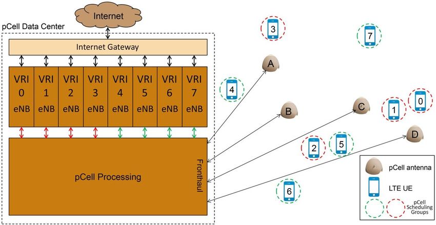
ARTEMIS NETWORKS WHITE PAPER
February 2015

2 Background
Artemis began pCell development over a decade ago as a project in the Rearden Companies
incubator with the goal to establish wireless Internet as a global ubiquitous utility for the 21st
century, much as electricity became a ubiquitous utility (in the developed world) in the 20th
century.

A decade ago, mobile data traffic was minimal, but given the simultaneous trends of (a) video
moving from broadcast/physical media to Internet streaming, and (b) Internet usage moving
from wired to mobile6, we projected mobile data demand to roughly double each year, or
about 1000X growth per decade. It quickly became apparent that the biggest challenge we
would be facing was the physics limit of wireless capacity (i.e. spectral efficiency or “SE”).

Given projected growth, it was quite clear that mobile data demand would far exceed the SE
limits of all known wireless technologies, even if all usable spectrum7 was allocated to mobile.

The severity of the problem was only widely acknowledged recently and dubbed the “Spectrum
Crunch”8. In 2010, the FCC released the data graphed in Figure 1, projecting U.S. mobile
demand exceeding capacity in 2013, and rapidly getting worse thereafter9.

                Figure 1: U.S. Mobile data demand vs. spectrum availability [FCC 2010]

The FCC projections were accurate. In 2013, U.S. mobile statistics should have been enviable…

   a. The U.S. had more LTE subscribers than all other countries in the world combined10.
   b. LTE represented 24.5% of all U.S. mobile connections, compared to 2.9% globally11.

An Introduction to pCell             Patents, Patents Pending                                   8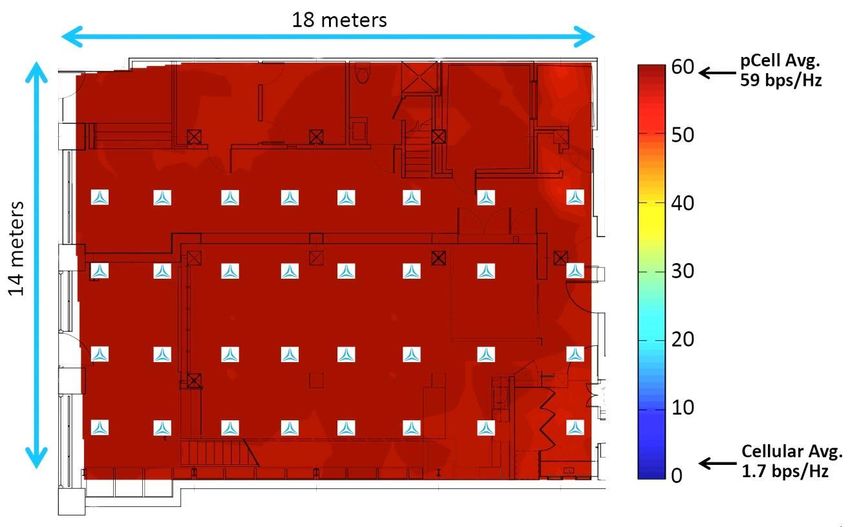
ARTEMIS NETWORKS WHITE PAPER
February 2015

   c. At 65% penetration, the U.S. was the only region of the world with mostly smart
      devices. Smart devices devour mobile data, accounting for 88% of global mobile traffic12.
   d. Most of U.S. mobile traffic was video13, enabled by LTE’s speed and smart device apps.

…but instead of enviable performance, U.S. mobile demand far exceeded spectrum capacity,
causing U.S. average LTE download speed to plummet from 2013 to 2014 by 32% to 6.5Mbps,
by far one of the slowest LTE speeds in the world14, per Figure 2. As a comparison, 3G HSPA
achieves faster speeds than 6.5Mbps15.

         Figure 2: Average LTE download speed by country 2013 vs. 2014 [OpenSignal 2014]

Ironically, slow U.S. LTE data rates are a consequence of LTE’s market success. The same result
is seen worldwide: Japan’s NTT DOCOMO launched LTE two years before competitors and holds
a wide market lead. The consequence of its “success” is an average download speed half that of
later Japan LTE market adopters that have far smaller subscriber bases16, almost as slow as U.S.
LTE. The unfortunate reality of cellular technology is market success results in declining service
quality, ultimately reaching the point where service becomes almost unusable. Such results are
already seen in dense cities like New York and Chicago17. New spectrum deployments may
briefly mitigate congestion18, but given the inexorable growth of mobile data demand,19 data
rates ultimately decline with market success20. Verizon CEO Lowell McAdam put it bluntly to
investors in 2013, “…it’s the physics that breaks it…you just run out of gas.”21

Costly efforts to increase cell density with small-cells (or tightly packed Wi-Fi access points)
have been unable to mitigate the performance decline. Small-cells suffer from increased inter-
cell interference and handoff overhead22, ultimately exceeding capacity gains which establishes
a practical upper limit for cell density, even disregarding the economic considerations of

An Introduction to pCell            Patents, Patents Pending                                    9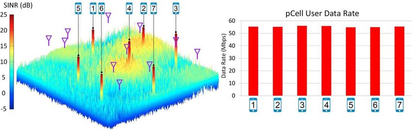
ARTEMIS NETWORKS WHITE PAPER
February 2015

backhaul, power, physical access, etc. So, as observed by the FCC and Verizon, the only known
option to significantly increase capacity is to allocate more spectrum for mobile use.

Unfortunately, the world is almost out of mobile spectrum. Only a narrow range of frequencies
that can efficiently penetrate obstacles are suitable for mobile23. Even if all of these frequencies
were allocated for mobile, it would only accommodate three years of mobile data growth24.
After that, all mobile spectrum would be gone for decades, with mobile congestion getting
worse every year. As noted in an October 2013 Wall Street Journal op-ed commemorating the
40th anniversary of cellular technology, “…wireless engineers will have to come up with a better
way to use the finite amount of spectrum they already have. If they don't, soon enough your
smartphone will remind you of the dial-up speeds of the 1990s.”25

Any doubts as to the severity of the mobile spectrum crunch have been brushed aside by the
sky-high bids in the recent FCC AWS-3 spectrum auction. US$44.9 billion was bid for 65 MHz of
U.S. mid-band spectrum, more than two times the US$22 billion that the most bullish analysts
had projected for the auction26. US$44.9 billion almost equals the total raised in all prior FCC
spectrum auctions—including auctions for far better low-band spectrum27—over the last 20
years28.

Cell phone pioneer Martin Cooper29 and FCC Commissioner Jessica Rosenworcel30 underscored
the urgency of the spectrum crisis in a September 2014 op-ed31, noting spectrum is a finite
natural resource that is quickly being exhausted:

       Spectrum is the basis of our new wireless world. But the laws of physics being
       what they are, we cannot create more. So we need to find ways to use the
       airwaves we have more efficiently.

They proposed to award 10 MHz of mobile spectrum (worth billions of U.S. dollars) for the first
to develop a practical technology that increases current spectral efficiency by 50 times.

As industry and governments are finally coming to the inescapable conclusion that 4G is unable
to meet mobile data demands today, let alone catch up to growing demands in the future, they
are urgently turning to new 5G technologies to overcome the spectrum crunch. In the last year
several heavily-funded 5G research efforts were initiated, with projected 3GPP standardization
efforts starting in 201632 and deployment dates ranging from the early- to mid-2020s33. All are
preliminary R&D efforts, exploring a wide range of directions, with no practical prototypes
operating today34. So, it is uncertain that 5G—whatever it ends up being—will be deployable by
the mid-2020s, let alone be capable of overcoming what will then be a massive spectrum deficit

An Introduction to pCell            Patents, Patents Pending                                     10
ARTEMIS NETWORKS WHITE PAPER
February 2015
relative to mobile data demand. Even if a viable 5G solution does arrive at some point in the
2020s, between now and then, mobile congestion may well become more than 100X worse
than it is today.
2.1 pCell: Meeting 5G requirements today, in compliance with 4G devices
In the early 2000s, we came to the same inescapable conclusion that most of the wireless
industry has only recently recognized: all known wireless technologies hit SE upper limits far
below what is required to meet skyrocketing wireless data demands. Fundamental R&D and a
complete rethink of wireless are necessary to achieve the required leapfrog in SE.
So, while most wireless research worldwide over the last decade focused on evolutionary
improvements of known wireless technologies (resulting in standards like LTE-A and 802.11ac),
we had concluded evolutionary approaches would fall far short of SE requirements, and were
entirely focused on revolutionary approaches that would leapfrog the SE limits of known
wireless technology and continue to scale to not just meet projected traffic demands, but
continue to keep up with growth. The outcome of our research, pCell technology, did indeed
require a revolutionary approach to wireless, and not only exceeded the original goals of the
research, but opened up new avenues of inquiry that led to many advantages in performance,
power and cost over conventional wireless technology in addition to pCell’s leapfrog in SE.
In fact, pCell’s actual performance today conforms closely to proposed 5G performance for the
2020s. In 2014 the ITU’s IMT-2020 (5G) Promotion Group presented a comprehensive vision for
what 5G would look like in the 2020s35, which is largely consistent with other recent 5G
visions36 and establishes an expert consensus on goals for the next generation of mobile
services. Table 1 lists some IMT-2020 requirements for 5G in the 2020s.
Target Traffic Connection Min Min Min
User
Spectral Density Density QoS Per-user Latency Device Device
Density
Efficiency per km2 per km2 Data Rate Cost Power
45 100 1 million Subway, Reliable, 100 IoT39 IoTARTEMIS NETWORKS WHITE PAPER February 2015 would be a revolutionary approach to wireless. Related to SE are IMT-2020 goals for traffic-, connection- and user-density as well as reliable and consistent QoS to make such performance predictable. The minimum per-user data rate reflects the expectation of a cellular architecture with cell-edge performance of at least 100Mbps, so that at least 100Mbps is available consistently throughout the coverage area. pCell has been extensively tested with unmodified LTE devices in bands 38, 39, 40 and 41 as well as with lab LTE devices in 900 MHz and 400 MHz bands, both indoor and outdoor. pCell can meet all of the light green IMT-2020 targets in Table 1 today on off-the-shelf LTE devices. pCell is compatible with unmodified LTE Release 8 and above devices such as iPhone 6, Galaxy S5, iPad Air 2, and LTE dongles. pCell achieves consistent and reliable SE throughout the coverage area in excess of the 5G target SE in Table 1, and can maintain a consistent and reliable per-user data rate in excess of 100 Mbps with LTE devices capable of that speed41. pCell far exceeds all of the Density requirements of Table 1, not only supporting devices at stadium/subway densities, but supporting densities of devices separated by only a few centimeters. pCell supports new protocols concurrently in the same spectrum as LTE and LTE-A devices such as protocols that would meet the dark green IMT-2020 targets in Table 1, which are not achievable within the LTE protocol42. As such, pCell future-proofs spectrum to allow concurrent use with yet-to-be finalized (or yet-to-be-conceived) standards. Current 5G R&D efforts, such as millimeter waves and massive MIMO, are in early prototyping stages and face numerous technical challenges before they can be considered for actual deployment. Initial experimental testbeds are far from achieving IMT-2020 spectral efficiency, traffic and device density, and reliability goals.43,44 To our knowledge, pCell is the only technology deployable in this decade, let alone in the next year, that can keep pace with mobile data demand or come close to achieving IMT-2020 5G performance goals. Despite this enormous performance advantage over LTE networks, pCell is actually less expensive and much faster to deploy, and far lower cost to operate than LTE networks, while maintaining compatibility with LTE devices. How pCell not only leapfrogs LTE performance, but also dramatically lowers CAPEX and OPEX is detailed in subsequent sections of this white paper. The next section explains why current wireless systems have hit upper limits in SE and Density and why a radical approach to wireless such as pCell is necessary to overcome these limitations. An Introduction to pCell Patents, Patents Pending 12
ARTEMIS NETWORKS WHITE PAPER
February 2015

3 The Limits of Cellular Architecture
One of the greatest revolutions in wireless history began on April 1973 when the first cellular
phone call was made by the inventor Martin Cooper at the original Motorola Corporation. The
first cellular systems began commercialization in the U.S. a decade later in October 1983,
ultimately defining the modern era of wireless. In just three decades, cellular has connected
half of the people on Earth45, evolving from exclusively voice traffic thirty years ago to primarily
video traffic today46. But cellular’s success has also exposed its limitations.

Within the scope of this white paper we will discuss three fundamental limitations to cellular:

   1. Inconsistent data rates due to rapid decay of RF power with distance
   2. Limited SE gain, relying upon multi-paths for spatial multiplexing (micro-diversity limits)
   3. Poor cell-edge performance due to inter-cell interference (macro-diversity limits)

3.1 Inconsistent data rates
Cellular networks are planned by design so that power within each cell drops off by the cell
edge, and as power drops, SINR 47 and data rate drop. Ericsson 48 shows the practical
implications of this effect upon 4G cellular networks in Figure 3: 10 Mbps is available at cell
center49, at mid-cell it drops by 10x to 1 Mbps, and by cell edge it drops another 10x to 0.1
Mbps. Thus, cellular architecture has a 100:1 data rate ratio from cell center to cell edge.

                     Figure 3: Steep decline of cellular data rates [Ericsson 2013]

An Introduction to pCell              Patents, Patents Pending                                    13
ARTEMIS NETWORKS WHITE PAPER
February 2015
The large dynamic range of 100:1 results in enormous data rate inconsistency throughout the
coverage area. This is visually illustrated in Figure 4 as a 3D signal-to-interference-plus-noise
ratio (SINR) heat map showing cellular base stations in an ideal layout50. Transmit power
attenuates proportionally to the nth power of the distance resulting in a “volcano” SINR shape
for each cell. The center of each volcano has peak (red) SINR and the edge has minimum (blue)
SINR.
Figure 4: Cellular data rate distribution: Hexagonal base station layout, Sparse users
The user data rate (depicted in a histogram to the right of Figure 4) drops with SINR. Depending
on the location, some users experience data rates close to the peak data rate of 56 Mbps51
(e.g., user 1 at the cell center), whereas others experience only 7 Mbps (e.g., user 7 at the cell
edge). This cellular heat map has seven users in a sparse arrangement, with one user per cell in
a random location. As can be seen, even with only one user per cell and ideal conditions,
cellular data rate is enormously variable.
Figure 5: Cellular data rate distribution: Hexagonal base station layout, Clustered users
The same ideal cellular base station layout is depicted in Figure 5, but showing all seven users
clustered within one cell. Now, the data rate for each user is not only impacted by how far it is
An Introduction to pCell Patents, Patents Pending 14ARTEMIS NETWORKS WHITE PAPER
February 2015
from the cell center, it is also affected by the large number of users sharing the same spectrum
and data capacity available in the one cell. The result is extremely low data rates for all users, as
shown in the histogram to the right. This is why areas with high densities of users, such as
stadiums, airports, tourist attractions, etc. suffer from such poor data rates per user.
An arbitrary base station placement with a sparse user arrangement is depicted in Figure 6 to
illustrate how poorly cellular performs when base stations are not placed in accordance with an
ideal cell plan, for example, to accommodate practical real estate restrictions. Cellular base
stations typically limit transmit power to avoid interference with adjacent cells, so inconsistent
spacing results in cells with rapid drop-off in SINR/data rates and large dead zones between
cells. For example, users 1, 5 and 6 are all in large dead zones. Although some are fairly close to
base stations, they have suboptimal performance because of the rapid SINR drop-off; e.g., at
the same distance from cell center in the larger cells of Figure 4, user 1 would have higher data
rate. Figure 6 clearly illustrates both the sensitivity of cellular architecture to base station
placement and how inter-cell interference limits SINR performance.
Figure 6: Inefficient Cellular data rate distribution: Arbitrary base station layout, Sparse users
In summary, cellular data rate has an extremely variable 100:1 dynamic range, performs poorly
in areas with high user density, and is highly dependent on specific base station placement.
Cellular 100:1 data rate variability is very inefficient for video traffic, which represents more
than 50% of U.S. mobile traffic and is growing at 69% CAGR globally52. Video requires high and
consistent data rates53 throughout the coverage area, resulting in extremely disproportionate
cell capacity consumption toward the cell-edge. For example, 5G specifications, such as IMT-
2020 in Table 1, in planning for very heavy video traffic, recognize the need for minimum
performance of 100 Mbps throughout the coverage area. With cellular, that mandates a 100
Mbps cell edge requirement, and thus a 100 * 100 Mbps = 10 Gbps cell-center requirement54
which not only must be supported by the cell base station, but by every user device near cell
An Introduction to pCell Patents, Patents Pending 15ARTEMIS NETWORKS WHITE PAPER
February 2015
center. Thus, a 100 Mbps consistency requirement becomes a 10 Gbps performance
requirement, an extremely high performance and power burden, particularly for user devices.
3.2 The limits of cellular micro-diversity
Current cellular systems utilize multiple antennas at transmit and receive sides of a
communication link to increase SE by exploiting multi-paths in the propagation channel (i.e.,
space diversity, or in particular micro-diversity55) via multiple-antenna spatial processing. The
simplest form of spatial processing originated at the beginning of 20th century with initial
experiments on phased arrays56 and later in the 1980s with digital beamforming57, utilizing
multiple transmit antennas to focus wireless energy to combat signal fading and reduce
interference. In 1992, pioneering work by Kailath and Paulraj58 enabled transmission of multiple
independent data streams over multiple-input multiple-output (MIMO) links via spatial
multiplexing59, followed in 2001 by the first commercial MIMO-OFDM system by Iospan
Wireless, founded by Paulraj.
Multi-antenna techniques are used in cellular systems either to improve coverage (via
beamforming or diversity schemes) or to increase SE (via spatial multiplexing schemes)60,61.
Figure 7 62 shows the average SE achieved through an evolution of increasingly efficient
standard protocols and technologies that exploit micro-diversity. Note that the primary
approach to improve SE in current and future LTE releases is to increase the MIMO order (i.e.,
number of antennas) at the base station and user devices.
Figure 7: Evolution of average DL SE through cellular standards [Rysavy 2014]
An Introduction to pCell Patents, Patents Pending 16ARTEMIS NETWORKS WHITE PAPER
February 2015
While—in theory—SE scales linearly with MIMO order63, in practice MIMO multiplexing gain is
achieved only in a high SINR or high SNR regime64 (e.g., close to the base station) and in space-
selective channels65. Channel space selectivity refers to statistical variations of wireless signal
amplitude at different points in space due to constructive and destructive interference of radio
waves as they propagate through multi-path environments66. Space selectivity depends on the
characteristics of the antenna arrays (e.g., spacing, polarization, radiation pattern, etc.) and the
multi-path channel (e.g., number of paths, angles of departure/arrival of the radio waves) 67.
Since the array geometry is constrained by the limited real estate available for commercial base
stations and user devices, MIMO performance mostly relies on the multi-paths available in the
propagation channel (or “resolvable paths”). In general, for a given MIMO order, the number of
resolvable paths defines the channel space selectivity and is proportional to the number of
independent data streams that can be sent concurrently over MIMO links (or “multiplexing
gain”)68.
In outdoor tests, the 2003 3GPP study in Figure 8 found between 1 and 6 resolvable paths with
an average of between 2 and 4 resolvable paths, depending on the environment. These results
are consistent with an Ericsson 201169 outdoor LTE MIMO 8x8 study showing at most a 4x gain
due to MIMO multiplexing, despite having eight antennas that theoretically could yield up to 8x
multiplexing gain if eight resolvable paths existed70.
Figure 8: Probability of resolvable propagation Figure 9: CDF of MIMO data rates
paths [3GPP 2003]71 [Ericsson MIMO 2013]72
In indoor environments, a 2004 IEEE 802.11n study73 found between 2 and 6 propagation paths.
These results are consistent with an Ericsson 2013 LTE MIMO 8x8 indoor study in Figure 9
which, despite having eight antennas (that theoretically could yield 8x multiplexing gain if eight
An Introduction to pCell Patents, Patents Pending 17ARTEMIS NETWORKS WHITE PAPER February 2015 resolvable paths existed), achieved only an average 4x multiplexing gain with a peak of 6x74. Commercial Wi-Fi MIMO 4x4 systems have shown to only achieve up to 2x indoors, despite a theoretical peak of 4x, with performance dramatically degrading with distance from the access point75. Therefore, in practical MIMO systems, multiplexing gain does not scale linearly with the number of antennas due to limited number of resolvable paths. MIMO has other limitations such as: (a) highly variable performance throughout the cell (e.g., cell center vs. edge), so MIMO cannot be relied upon for services requiring sustained high data rates, such as video, which today make up the bulk of mobile traffic76, (b) MIMO cost grows rapidly with MIMO order, as each antenna requires a closely-spaced, but isolated, RF chain and computational complexity grows dramatically, and (c) performance degrades due to Doppler effects and channel aging from user and environment motion77. Despite these limitations, currently MIMO remains the best available solution to increase average SE of cellular systems, albeit limited to average multiplexing gains of at most 4x in practical systems. A number of other approaches to MIMO have been explored to improve space selectivity and achieve higher multiplexing gains. One solution is to separate the receiving antennas as in multi-user MIMO (MU-MIMO) systems. MU-MIMO links are established between a base station antenna array and multiple users equipped with one or multiple antennas. The theory behind MU-MIMO systems was formulated in the seminal work by Caire and Shamai78 followed by Yu and Cioffi79,80 and Goldsmith et al.81,82 based on the idea of “dirty paper coding” (DPC)83,84,85. One of the first commercial systems employing MU-MIMO technology was designed by ArrayComm using space division multiple access (SDMA) techniques to form individual focused beams to different users86. The MU-MIMO scheme is part of the LTE standard, limited to a maximum of four users with only low-resolution channel state information (CSI) available87. Another technique that has emerged in the last three years is “massive MIMO”88,89. The basic concept of massive MIMO is to have far more base station antennas than users and exploit the excess antennas to increase space selectivity and create independent spatial channels to multiple concurrent users via beamforming. Massive MIMO is still in early stages of academic research and only recently a limited number of propagation studies have been published to show its performance with two types of array configurations (i.e., linear and cylindrical arrays)90. Those measurement campaigns verified experimentally that indeed the limited space selectivity achievable in MIMO channels (due to collocation of antennas within limited real estate) can be compensated by a very large number of excess antennas. But it is yet unclear whether the multiplexing gain achievable through massive MIMO can scale linearly with the number of user antennas to achieve high spectral efficiency required in next generation An Introduction to pCell Patents, Patents Pending 18
ARTEMIS NETWORKS WHITE PAPER
February 2015

wireless systems. Other practical limitations are: i) highly complex base stations equipped with
many tightly-packed, but isolated RF chains, increasing design costs and power efficiency
requirements; ii) degradation due to pilot contamination as the technology is implemented
within a cellular framework; iii) degradation due to Doppler effects and channel aging from user
and environment motion; and iv) undefined interoperability with existing cellular networks and
devices that may delay practical deployments91,92,93.

Because MIMO performance is inherently unpredictable in practical deployments, MIMO can
only be deployed as an “as-available” enhancement to baseline SISO (single-input single-
output) performance. Thus, while MIMO increases the peak and average data rate of a wireless
network, cellular multi-antennas systems only marginally increase the minimum data rate
(through beamforming providing higher SINR), which is still defined by SISO performance
(typically at the cell edge). Services reliant on consistent data throughput, such as streaming
video—the majority of data traffic today—cannot rely upon MIMO enhancements.

In summary, practical MIMO systems can achieve an average multiplexing gain up to 4x,
peaking at 6x, which is not sufficient to meet the target SE of next generation wireless systems.
Moreover, MIMO performance is highly variable and unpredictable, arbitrarily determined by
the characteristics of objects in the environment, the distance from cell center and user and
environment motion. While MIMO increases the peak and average data rate of a wireless
network, the minimum data rate is still defined by SISO data rate, which limits MIMO’s benefit
for services reliant on consistent data rate, such as streaming video.

An Introduction to pCell           Patents, Patents Pending                                   19
ARTEMIS NETWORKS WHITE PAPER
February 2015

3.3 The limits of cellular macro-diversity94
In cellular networks, as a user device moves away from its serving cell, it is handed off to the
adjacent cell’s serving base station for uninterrupted service. Virtually all mobile networks
utilize this basic cellular network architecture (to the point where the terms “mobile” and
“cellular” are used synonymously). While cellular architecture has served the world well for
over thirty years, as networks have become denser, cellular is approaching inherent capacity
limits.

Cellular systems seek to constrain RF propagation within 2D geometric layouts to minimize
interference between adjacent cells. From left-to-right, Figure 10 illustrates the difference
between conceptual and real-world depictions of cellular layouts. The leftmost diagram shows
an ideal base station placement (blue dots) with the ideal propagation that would occur with
free-space path-loss. When the same carrier frequency is used for adjacent cells with universal
frequency reuse95 (as in current LTE systems), inter-cell interference occurs in the overlapping
regions. The effect of inter-cell interference becomes more severe in real-world scenarios
characterized by irregular cell shapes in the middle diagram, due to shadowing from obstacles
in the propagation environment. Finally, on the far right is a diagram that approaches reality,
where the base stations are in sub-optimal locations and there are real-world obstacles,
resulting in not only irregular cell shapes, but different cell sizes and considerably more severe
inter-cell interference effects. Further, the rightmost diagram only shows a snapshot in time;
real-world shadowing is variable, producing changing cell shapes and interference patterns96.

                       Figure 10: 2D cell geometry: Conceptual to Real-world

An Introduction to pCell            Patents, Patents Pending                                   20
ARTEMIS NETWORKS WHITE PAPER February 2015 3.3.1 Small-cells and inter-cell interference coordination Inter-cell interference effects exacerbate when cell density increases to support more subscribers and heavier usage per unit area, as wireless operators seek to increase their network capacity. For example, in densely populated areas (e.g., downtown areas, shopping malls, airports and stadiums) current cellular networks have been testing small-cells (e.g. pico- cells and femto-cells) and Heterogeneous Networks (“HetNets”, where small-cells are overlaid within the macrocell umbrella)97. Since small-cells are far more dense than macrocells, the number of overlapping regions with inter-cell interference depicted in the rightmost diagram in Figure 10 increases substantially98. Further, small-cell base stations are typically installed near street level (e.g. lamp posts), which makes propagation highly unpredictable (unlike conventional macrocells) with large signal variations between LOS paths (or urban “street canyons”99) and NLOS paths (e.g., outdoor-to-indoor propagation through buildings)100, yielding cell geometries that are far more irregular than those shown in the rightmost diagram of Figure 10. In addition to inter-cell interference, these complex propagation patterns cause unnecessary handoffs, which make mobility in small-cell networks highly inefficient. Frequent handoffs may trigger undesired radio link failures (due to dragging effects, when the network waits too long before initiating handoff) or ping-pong effects (when handoff is initiated multiple times unnecessarily between two adjacent cells)101,102. Depending on the speed of mobile subscribers, the rate of handoff failure and ping-pong effects can be as high as 60% and 80%, respectively103, yielding a large amount of control overhead that reduces cell throughput. These issues are exacerbated by the highly-degraded small-cell edge performance caused by extensive inter-cell interference104,105,106. The LTE standard attempts to solve these issues through self-organizing networks (SON), consisting of one centralized unit self-optimizing the configuration of adjacent cells to enable load balancing, reduce handoff overhead and mitigate inter-cell interference. SON uses inter- cell interference coordination (ICIC) as one method to mitigate inter-cell interference,107,108 through “cell-autonomous” schemes employing different frequency reuse patterns (e.g., full frequency reuse, hard frequency reuse, fractional frequency reuse) or coordinated techniques enabling cooperation between base stations to coordinate the allocation of time/frequency resources. ICIC does not remove interference; it only avoids interference by frequency coordination, and consequently throughput gains are only limited. Field trials with SON have demonstrated only marginal average throughput improvements on the order of 10%109. An Introduction to pCell Patents, Patents Pending 21
ARTEMIS NETWORKS WHITE PAPER
February 2015

In summary, as wireless operators have turned to small-cells and HetNets to increase
subscriber density, increased hand-off overhead and inter-cell interference quickly has reduced
the capacity gains from higher cell density, ultimately hitting a limit to the capacity achievable
in a given area, despite the use of SON and ICIC techniques. The impracticality of small-cells is
reflected in weak market acceptance: despite widespread promotion of small-cells as a solution
to mitigate congestion, small cell adoption by mobile operators has been very limited, falling far
short of projections110.

3.3.2 Network MIMO and CoMP
An alternative approach to mitigate inter-cell interference is to coordinate transmissions from
multiple base stations in so-called “network MIMO”, “distributed MIMO” or “CoMP” systems.
Network MIMO was first proposed in 2005 with the goal of improving SINR in cellular systems
to increase SE via MIMO spatial multiplexing111 (which only works in a high SINR regime, as
described in the Section 3.2). Theoretical analysis of network MIMO in ideal complex Gaussian
channels112 and simulations in indoor channel models113 showed significant gains in SE over
conventional cellular systems, although these gains do not grow linearly with the number of
base stations in the network and are limited114. While theoretical analysis of network MIMO
shows up to 5x gain over conventional systems using power control to mitigate interference115,
recent lab prototypes have demonstrated only up to a 4x gain in SE116, comparable to
conventional MIMO. Base station coordination has become part of the LTE-Advanced standard
for 4G cellular systems with so-called coordinated multi-point (CoMP)117 schemes, namely
“joint processing” (JP) and “coordinated scheduling/beamforming” (CS/CB) 118 . CoMP only
enables cooperation among adjacent cells and its performance degrades when LTE-compliant
limited feedback mechanisms are employed, due to coarsely quantized CSI119,120. Further, CoMP
is highly sensitive to Doppler effects and channel aging from motion by the user and the
environment121. Practical field tests have demonstrated at most 30% gain in average downlink
throughput with CoMP122,123,124,125.

3.4 Other limitations of cellular systems
The following subsections describe other practical limits encountered in the deployment of
current and next generation cellular systems.

3.4.1 3D environments
Although we’ve thus far illustrated 2D horizontal cellular layouts, the real world is 3D with a
vertical dimension, resulting in additional challenges for cell planning, particularly in urban
environments, such as the example depicted in Figure 11. An indoor user in a high-rise building
might well experience LOS from many cell base stations, with no base station having much

An Introduction to pCell            Patents, Patents Pending                                   22
ARTEMIS NETWORKS WHITE PAPER
February 2015

different power than any other. Beyond the
challenge of deciding which cell should serve
the user device, the combined downlink
transmissions from interfering cells results in
low SINR to the user, while the user uplink
transmission interferes with whichever cells
are not chosen to be the serving cell126. Given
that 80% of mobile Internet use is indoors127
and 53% of people live in urban areas (growing
about 0.5% every year) 128 , challenges from
mobile usage in tall structures will have an
increasing impact on global mobile capacity
and, accordingly, it has been considered as a
case study by 3GPP LTE Rel. 13129.                       Figure 11: 3D high-rise cellular challenges

In general, cellular provides only approximate user location information, particularly in dense
urban areas with large 3D structures, where accuracy errors can exceed 100 meters 130.
Accurate 3D location information (e.g. identifying the correct floor and room in a building) is
critical for first responders in emegency situations and also can be useful for personal and
commercial applications.

3.4.2 Crisis situations
As payphones and landlines have rapidly vanished from public locations, homes and
businesses131, the world has become almost entirely reliant upon mobile communications in
crisis situations. Because cellular architecture inherently divides the coverage area into largely
non-overlapping cells, if a single cellular base station fails for any reason (e.g. loss of power or
backhaul, or if it is damaged or destroyed), the entire cell loses coverage. Power loss can be
mitigated by batteries or generators, but if an incident results in physical harm to a base station
or its connectivity, the base station’s coverage area will lose connectivity. Where operators
share mobile infrastructure132, damage to a shared cell tower or its backhaul can result in the
loss of all mobile service in the surrounding area, as shown in Figure 12.

An Introduction to pCell            Patents, Patents Pending                                       23
ARTEMIS NETWORKS WHITE PAPER
February 2015

                           Figure 12: Cellular coverage loss in a crisis situation

A crisis situation at a given location can result in a vast number of people in the affected area
attempting to initiate calls, and once the news of the incident is widely known, a vast number
of people attempting to call into the affected area. First responders urgently need
communications to and from the affected area, potentially requiring video teleconferencing so
remotely-located specialists can make visual assessments of the situation. Even if the crisis
situation does not damage the cellular infrastructure, a given cellular base station capacity is
sized for typical peak usage which assumes a small fraction of people within a cell are
concurrently engaged in communications. Although there have been proposed SON
technologies to theoretically balance loads between adjacent small cells, a sudden surge of a
large percentage of people in the area concurrently attempting connections will overwhelm all
base stations serving the area, regardless of how loads are balanced, potentially resulting in
little or no service for anyone. For example, in the wake of the Boston Marathon bombing in
2013, the sudden surge in mobile traffic in the area overwhelmed all major U.S. carriers
resulting in no service at all133.

As previously noted, cellular networks are only able to provide very coarse location
information, so even when base stations are not overwhelmed, they often are unable to
provide useful location information to find people who need help, particularly if they are
located in tall buildings. In contrast, a landline call can typically pinpoint the location of the
caller at the installation address of the landline, whether an apartment in a tall building in a
dense city or a farmhouse in a rural area. Cellular technology is unable to come anywhere close
to this level of precision, particularly in densely populated areas.

3.4.3 Security vulnerabilities
Transmissions by conventional wireless systems, including cellular, can be intercepted by an
eavesdropping device within range of the transmitter. Current cellular systems utilize key-based
cryptography to encrypt data transmissions. Even with the strongest encryption system, if the

An Introduction to pCell                Patents, Patents Pending                               24
ARTEMIS NETWORKS WHITE PAPER February 2015 key is compromised, it is possible to intercept and decrypt data transmissions. For example, it was recently reported the encryption keys of potentially most SIM cards in use today have been compromised134. Because cellular transmissions can be easily intercepted, this means that possibly most cellular communications in the world have been compromised, vividly illustrating the inherent security vulnerability of cellular communications. 3.4.4 Millimeter wave performance in cellular networks Millimeter waves are defined to be at frequencies much higher than those of conventional cellular systems (e.g., between 30 GHz and 300 GHz of the electromagnetic spectrum), and have been proposed for future 5G cellular networks. The principle benefit of millimeter waves is the vast amount of unused millimeter wave spectrum available, but the fundamental drawback is millimeter waves incur high attenuation from most natural objects (including heavy rain and fog) and man-made objects other than clear glass135, behaving much like light waves. Experiments with high-gain directional antenna arrays (analogous to a sweeping spotlight) have been used to sweep through coverage areas to demonstrate that many non-obstructed areas can be reached by millimeter waves136. But millimeter waves, like light, are unable to reach locations only reachable by penetration of non-transparent objects, requiring extensive antenna placement throughout the coverage area137 (analogous to installing enough spotlights to illuminate every outdoor and indoor location in the coverage area on a dark night). Millimeter wave research thus far has largely been focused on propagation studies and to date, little work has been done to assess the unique propagation characteristics of millimeter waves within a cellular architecture. While millimeter waves, even as a focused beam, are largely blocked by walls, they propagate through air and clear glass very efficiently, resulting in highly irregular cell shapes. For example, a millimeter wave small-cell within a room might not penetrate the walls of a room, but could extend very far through the open windows of the room or through an open door, interfering with cells serving the areas outside of the room. If shades are drawn or the door is closed, the millimeter waves would be blocked, dramatically and dynamically changing the shape of the cell. It is unknown how long it will be before millimeter wave systems can be deployed on a commercial basis or what form such networks and user devices will take. Whether cellular architecture can be used efficiently with millimeter waves remains an open area of research. An Introduction to pCell Patents, Patents Pending 25
ARTEMIS NETWORKS WHITE PAPER February 2015 3.5 Summary: Cellular architecture has reached capacity and reliability limits While cellular has served the world well for over 30 years, cellular has reached its limits, given today’s requirements for wireless networks in terms of capacity, reliability, consistency, density and public safety. We summarize the fundamental limits of cellular architecture as follows: Inconsistent data rate throughout the coverage area (100:1 cell center to cell edge) Poor cell-edge performance further degraded by inter-cell interference Poor performance in high-density user scenarios due to bandwidth sharing Inability to scale capacity through small-cells due to uncontrolled inter-cell interference Large handoff overhead, particularly in small-cell deployments Limited and inconsistent capacity gains through MIMO (only up to 4x over SISO) MIMO limited to 4x average SE gain in ideal scenarios, no gain in unfavorable scenarios Spatial processing (MIMO, CoMP, beam-forming) highly sensitive to Doppler/mobility Inflexible antenna installation, requiring specific and expensive base station locations Poor vertical 3D performance in high-rise buildings Inability to accurately determine user location Crisis situations result in loss of coverage and/or severe congestion Cellular transmissions are vulnerable to interception and decryption Despite these inherent limitations, cellular is still taken as a given as the architecture for mobile communications, and virtually all mobile wireless development is constrained within a cellular framework and its limitations, resulting in marginal improvements at best. The only way to overcome the above limitations—and all can be overcome—is to transition from the traditional cellular architecture to a new architecture for wireless, designed from the outset to serve today’s requirements for wireless networks, thus delivering scalable, consistent capacity in even high-density scenarios, and supporting public safety needs. And, on a practical level, ideally this new wireless architecture would remain compatible with standard LTE and Wi- Fi devices and use readily-available backhaul infrastructure so that it can be immediately deployed and put into use. This new wireless architecture is pCell. An Introduction to pCell Patents, Patents Pending 26
You can also read