FIRTH CHIMNEYS AND OPEN FIREPLACES
←
→
Page content transcription
If your browser does not render page correctly, please read the page content below
3132

FIRTH CHIMNEYS AND
                     December 2010

OPEN FIREPLACES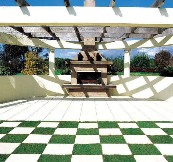
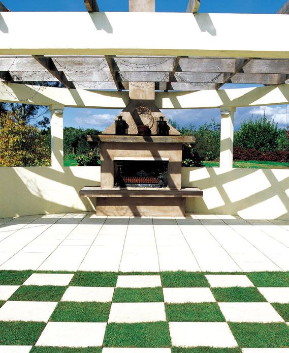
Precast open fireplaces continue to enjoy popularity with many
   architects and builders, because of their aesthetic appeal and ease
   of construction.

   HOW IT WORKS

   Room air is drawn into the fire chamber and through           Foundation
   the fuel bed, thereby supplying oxygen for the burning
                                                                 The foundation should be excavated into naturally
   process. Combustion gases and smoke rise from the
                                                                 solid ground (never less than 300mm deep) and be
   burning fuel to the throat and then through the flue to
                                                                 of a sufficient area to ensure stability. The foundation
   the outer air. A correct balance between the sizes of
                                                                 pad should be of reinforced concrete never less than
   fire chamber, throat, flue cross sectional area and flue
                                                                 150mm thick.
   length are essential to a continuous upwards discharge
   draft of combustion gases and smoke. Satisfactory
                                                                 Flue
   dispersal of combustion gases and smoke could be
   impeded by a flue being too big or too small in relation      The height of the chimney shaft above the roof line
   to the size of the fire chamber.                              should be greater than 600mm and less than 2400mm
                                                                 above the highest part of the roof intersect. The top of
                                                                 the chimney has to be more than 1500mm from the
                                                                 nearest point of the roof measured horizontally.

                                             Flue                Height
                                                                 The maximum height for a sectional pumice chimney
            Lintel
                                                                 is 9140mm, measured from the ground to the highest
                                                                 point of the chimney cap.
         Mantle
                                             Gathering
  Surround                                                       Supports
                                                                 Our sectional pumice chimneys should be secured to
                                             Smoke Shell
                                                                 the building at the ceiling, the roof line and at each
                                                                 floor level with galvanised metal straps, at no less
                                             Throat
                                                                 than intervals of 2.4 metres. Suitable provision will
                                                                 need to be included in the design of individual houses
                                             Fire back
                                                                 to ensure that they possess adequate strength to resist
Front
Hearth                                                           the horizontal wind and seismic loads which will be
                                             Fire chamber
                                                                 transferred into the house frames from the chimney.
                                             Grate

                                             Tip Plate & Frame   Mortar Joints
                                             Ash-dump
  Hob                                                            To join the pumice sections together, a full bed of
                                                                 premixed mortar should be used.

     Back
     Hearth

   Standard
   The means of compliance is NZS 1900, chapter 7
   cover manufacturing and safety requirements for open
   fireplaces and small chimneys.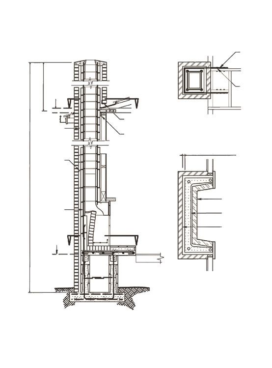
Reinforcing                                                 Base Slab
The chimney should have continuous vertical reinforcing     The base on all chimneys for an outdoor setting must
consisting of four 12mm deformed steel rods. The            have a base larger than the chimney. This is to prevent
reinforcing extends the full length of the chimney above    the chimney from falling over. An engineer should be
the gathering. All reinforcing should be grouted with       consulted to provide the correct dimensions for this
a high strength low shrinkage pourable cementicious         base.
grout.
                                                            Chimney Selection
Fire back                                                   The chimneys approved for an outdoor setting are;
Fire bricks should be laid on the flat using a refractory
                                                            •   Super Heat Master chimney
mortar, the sides of the fire chamber should be vertical,
                                                            •   Standard Log Burner chimney
but in plan view should be angled so as to reduce the
                                                            •   Super Log Burner chimney
back width of the chamber, this back width should be
                                                            •   Super Room Warmer chimney
the same as that of the chosen grate.

                                                            FOR ALL NON STANDARD APPLICATIONS AN
The fire back should rise vertically for the first
                                                            ENGINEER SHOULD BE CONSULTED.
150mm and then slope forward in a straight line
towards the throat.

The fire back must not be laid with a cruve as it rises,                 Timber
                                                                         Framing
because this could cause smoke to be curled forward

                                                                                                                 Cement
                                                                                                                 Compo.
of the lintel and into the room. There should be a space
between the structural chimney and the fire back, this
space being filled with fine dry pumice and capped with
a smoke shelf which shall be dished.                                    Air Tight                   TW
                                                                        Seal

Throat
                                                                                           TH
The throat should be the full width of the fire chamber                  As
and relatively narrow e.g. between 90mm and 100mm.                     Narrow
                                                                                       Strai Curved)

                                                                                                         Fireb
                                                                     As Possible
                                                                                        (Not

The fireback should rise at least 75mm higher than the

                                                                                                              ricks
                                                                                            ght S

lintel.
                                                                 H

                                                                                                  lope

Outdoor Chimney
For the outdoor chimney to draw properly, a minimum                                    D
height of between 2.6 - 3.0m is recommended. For
finishing - we recommend plastering outdoor chimneys
only.

                                                                                                           Fine Shingle
Bracing Requirements                                                                                          Filling
The maximum a chimney can be built free standing
without bracing is 2.4 metres. Because of the reinforcing
detail both the Log Burner chimneys require a wing
wall built behind the chimney for bracing purposes. The
Log Burner chimneys require bracing for the bases, sill
block rectangle, sill block gathering and in the case of
the Standard Log Burner the extension gathering as
well. Above this wing wall, 2.4 metres of freestanding
flue blocks including the cap can be installed.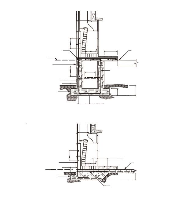
Inside
                                                          260 x 150          230                        Standard Flue Cap
                                                                                    390     490
                                                          Inside
                                                          335 x 230          150                        Standard Flue Block
                                                                                    410     510

                                                                       395                              Extension Gathering

                                                                             400           1090

                                                                                                        Deflector
                                                                       250

                                                                              570               1090

Standard Heat Master Chimney                                                                            Base Section
Base Section             Standard Flue Cap                             710
Rectangle Gathering      Firebricks (80)                                                  890
Extension Gathering      Steel Rod D12 (10 metres)                            570               1090
Standard Flue Blocks     Refractite Cement (16kg)

Note: Steel is not supplied.

                                                     Inside                                             Super Flue Cap
                                                     260 x 150          70                       1090
                                                                             410
                                                     Inside                                             Super Flue Block
                                                     350 x 250         150                       1090
                                                                             410
                                                                                                        Open Gathering

                                                                       300                       1090
                                                                             405

                                                                                                        Deflector
                                                                       250
                                                                              570               1090

                                                                                                        Base Section
                                                                       710
Super Heat Master Chimney
                                                                                          890
Base Section             Super Flue Cap
                                                                              570               1090
Rectangle Gathering      Firebricks (80)
Open Gathering           Steel Rod D12 (10 metres)
Super Flue Block         Refractite Cement (16kg)

Note: Steel is not supplied.

Reinforcement Details
                                                                 210

                 Hole Size 50mm dia.
                                                                       300
                                                                 65

 50                                                  50
         300              400             300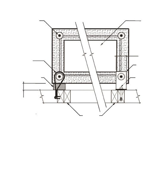
Inside
                                                          260 x 150           230                            Standard Flue Cap
                                                                                         390    490
                                                          Inside
                                                          335 x 230           150                            Standard Flue Block
                                                                                         410    510

                                                                         380                                 Extension Gathering

                                                                                   400         1090

                                                                                                             Sill Block Gathering
                                                                300
                                                                                               1600
                                                                             405
                                                                                                             Sill Block Rectangle

                                                                300
                                                                                                  1600
Standard Log Burner Chimney                                                  580
Base Section Lower       Standard Flue Block                                                                 Base Section Upper
Base Section Upper       Standard Flue Cap
                                                                                               1410 600
Sill Block Rectangle     Firebricks (120)                       355                                1

Sill Block Gathering     Steel Rod D12 (10 metres)                           590
                                                                                                             Base Section Lower
Extension Gathering      Refractite Cement (24kg)
                                                                355                            1410 600
                                                                                                   1
Note: Steel is not supplied.                                                 590

                                                                                                             Super Flue Cap
                                                                              70                      1090
                                                                                     410
                                                                                                             Super Flue Block
                                                                             150
                                                                                                      1090
                                                                                     410
                                                                                                             Still Block Gathering
                                                                                                 1100
                                                                    300                          1600
                                                                              410
                                                                                                             Still Block Rectangle

                                                                    300
Super Log Burner Chimney                                                                              1600
                                                                               580
Base Section Lower       Super Flue Block                                                                    Base Section Upper
Base Section Upper       Super Flue Cap
Sill Block Rectangle     Firebricks (120)                            360                       1410 600
                                                                                                   1
Sill Block Gathering     Steel Rod D12 (10 metres)                             590
                                                                                                             Base Section Lower
                         Refractite Cement (24kg)
                                                                     360                       1410 600
                                                                                                   1
Note: Steel is not supplied.                                                   590

Reinforcement Details
                                                              60

                 Hole Size 50mm dia.
                                                                   460 crs
                                                              60

 60                                                  60
                          1470 crs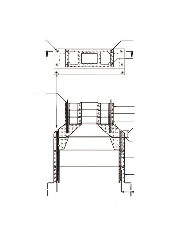
Inside
                                                          260 x 140          230                        Standard Flue Cap
                                                                                    390     490
                                                          Inside
                                                          335 x 230          150                        Standard Flue Block
                                                                                    410     510

                                                                       430                              Extension Gathering

                                                                              560               1090

                                                                                                        Deflector
                                                                       250
                                                                              570               1090

Standard Fireglow Chimney                                                                               Base Section
Base Section             Standard Flue Cap                             710
Deflector                Firebricks (80)                                                  890
Extension Gathering      Steel Rod D12 (10 metres)                            570           1090
Standard Flue Block      Refractite Cement (16kg)

Note: Steel is not supplied.

                                                     Inside                                             Super Flue Cap
                                                     260 x 150          70                       1090
                                                                             410
                                                     Inside                                             Super Flue Block
                                                     350 x 250         150                       1090
                                                                             410
                                                                                                        Open Gathering
                                                                       300
                                                                                                 1090
                                                                             405

                                                                                                        Deflector
                                                                       250
                                                                              570               1090

                                                                                                        Base Section
                                                                       710
Super Fireglow Chimney                                                                    890
Base Section             Super Flue Cap                                                         1090
                                                                              570
Deflector                Firebricks (80)
Extension Gathering      Steel Rod D12 (10 metres)
Super Flue Block         Refractite Cement (16kg)

Note: Steel is not supplied.

Reinforcement Details
                                                                 210

                 Hole Size 50mm dia.
                                                                       300
                                                                 65

 50                                                  50
         300              400             300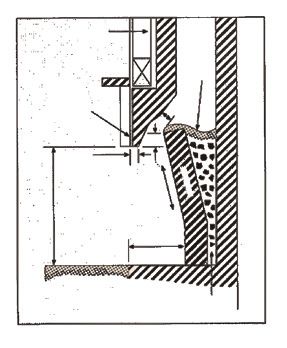
Inside
                                                            240 x 140          230                              Standard Flue Cap
                                                                                         390     490
                                                            Inside
                                                            335 x 230          150                              Standard Flue Block
                                                                                         410     510

                                                                        430                                     Extension Gathering

                                                                                   600                  1095

                                                                                                                Gathering Slab
                                                                         76
                                                                                                         1244
                                                                                   600

                                                                                                                Deflector
                                                                        485
Standard Room Warmer Chimney                                                                      1040
Base Section             Standard Flue Cap                                                          1244
                                                                                   600
Deflector                Firebricks (80)
Gathering Slab           Steel Rod D12 (10 metres)                                                              Base Section
Extension Gathering      Refractive Cement (16kg)                       480
                                                                                               1040
Standard Flue Blocks                                                                                  1244
                                                                                   600

Note: Steel is not supplied.

                                                                                                                Super Flue Cap
                                                       Inside
                                                       260 x 150              75                       1090
                                                                                    410
                                                                                                                Super Flue Block
                                                       Inside
                                                                          150
                                                       350 x 250                                       1090
                                                                                    410
                                                                                                                Open Gathering
                                                                          300
                                                                                                       1090
                                                                                    410
                                                                                                                Gathering Slab
                                                                         75
                                                                                                         1244
                                                                                600

                                                                                                                Deflector
                                                                        485
                                                                                                 1040 4
                                                                                                    124
                                                                                600
Super Room Warmer Chimney
Base Section             Super Flue Cap                                                                         Base Section
Deflector                Firebricks (80)                                480
                                                                                               1040
Gathering Slab           Steel Rod D12 (10 metres)                                                    1244
                                                                                600
Extension Gathering      Refractive Cement (16kg)
Super Flue Blocks

Note: Steel is not supplied.

                                                     50
Reinforcement Details
                                                                   50

                   Hole Size 50mm dia.
                                                                   50

  120                                            120
             300          400            300
TECHNICAL SPECIFICATION - CHIMNEY FOUNDATION

   Figure 1

                                      300mm
                                        lap

     75mm hearth slab
     D10 at 255mm ctrs each way                                     500mm
                                                                                       Timber floor (double joists
                                                                     max               each side of hearth slab)
     Floor line for
     internal chimney
     Foundation for base
                                      300mm

                                                    300mm             D12 at 400mm ctrs (300mm legs)
                                        lap

                                                      lap
     D12 starters at 400mm
     max ctrs to match
                                   150mm                              R6 U bars at 200mm ctrs in walls
     vertical rods in chimney

                                                                                      300mm
                                                                                        min
                                                                        200mm

                                                                                min

     Chimney foundation slab.
     D12 at 300mm ctrs each way
     or 661 mesh top and bottom
                                                       300mm leg

                                              (A) Suspended Floor
                                     300mm
                                       lap

      D12 starters at 400mm                                           400mm lap
      max ctrs to match
      vertical rods in chimney                                                          Ground Floor Slab
                                   150mm
      Floor line for
      internal chimney
      Chimney foundation slab.
      D12 at 300mm ctrs each way
      or 661 mesh top and bottom
                                                                      D12 at 400mm ctrs max (300mm leg)
                                              (B) Slab On Ground      Lap 400mm with slab reinforcement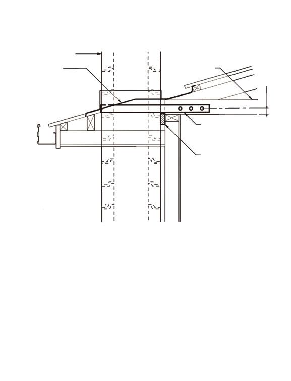
TECHNICAL SPECIFICATION - FLOOR AND ROOF BRACKETS

   Figure 2

     Chimney Stack

     Flashing                                                                Ceiling Joist

                                                                                                                   min 400mm
                                                                                       50mm x 4mm Galv. steel
                                                                                       strap. Three M12 bolts at
                                                                                       75mm min ctrs

                                                                                       Packer each side
                                                                                       See NZBC acceptable solution
                                                                                       B1/AS3 Paragraph 1.7.2

                                            Floor and Roof Brackets

          Note:
          Although drawn for roof restraint of a chimney on an exterior wall, the bracket details also apply to
          an interior chimney and floor restraint of chimneys.
TECHNICAL SPECIFICATION - CHIMNEY RESTRAINT
Figure 3
D12 grouted into
50mm Ø duct Flue
90mm
Fixing Tie
See Note 1
Fixing Bracket
See Note 2
Packer. See
NZBC B1/AS3
Fix Bracket to stud
Paragraph 1.7.2
with 12mm Ø
coach screw
50mm
Double Stud
Option A Option B
Notes: Notes:
1. Ties shall comprise 4mm galvanised hairpins located in 1. Brackets shall be made from 5mm thick M.S. angle with a
the mortar joints between units at no more than: 50mm hole drilled to suit the reinforcing duct. Locate brackets
in the mortar joints between units at no more than:
480mm maximum centres for stacks up to 600mm wide
320mm maximum centres for stacks over 600mm wide 480mm maximum centres for stacks up to 600mm wide
320mm maximum centres for stacks over 600mm wideTECHNICAL SPECIFICATION - STEEL REINFORCING DETAILS
Figure 4
Two outside stack
Base rods to be rods pass
bonded 200mm min continuously from
into gather with a high foundation to base
strength grout to gather to stack
A A
Two inside stack
rods to be fixed a
minimum of
200mm into gather
with a high
strength grout
Plan
50mm dia
ducts for
reinforcing
rods
Chimney stack units
D12 grouted in
50mm diameter duct
50mm dia duct for
reinforcing in gather
D12 in high strength
grout over length of
200mm min
gather
D12 grouted in
50mm diameter duct
Chimney base
Chimney Foundation
and starters as in Fig. 1
Section A-ATECHNICAL SPECIFICATION - BRICK VENEERS
Figure 5
Secured to wall (internal
or external) at no less than
intervals of 2.4 metres.
50mm x 4mm
U strap at
roof level
above roof level fixing
2.4m max cantilever
See Note
fix to ceiling
joist with
3 x M12 galv.
bolts @
A A 75mm min
centres
80 x 60 x 5mm M.S. angle
or 65 x 10mm M.S. flat Section A-A
Grouting
between Packer each side. See
chimney & brick NZBC acceptable solution
veneer shall be B1/AS3 Paragraph 1.7.2
17.5 mPa
50mm grouting cavity
Bricks shall
be fixed to
Max height 9m
precast
chimney with
brickweld
between the
joints.
Firebricks
D12 at 400mm
max ctrs Precast Pumice Units
(300mm min laps)
Brick Veneer
See Note
B B
Section B-B
Note:
Figure 5 has been drawn for the chimney being
exterior to the building
Vertical Section The dotted lines indicate the ceiling joists and floor for
an internal chimney.SUSTAINABILITY: THE FIRTH CONCRETE & CONCRETE MASONRY SUSTAINABILITY LIFECYCLE
n
4 Environmentally compliant manufacturing plants n
4 Most wash water returned from construction sites For more on Firth’s
n
4 Surplus water and some aggregates recycled n
4 Highly durable, low maintenance buildings and no rot contribution to building
n
4 Low transport impacts n
4 High degree of noise control a sustainable tomorrow
n
4 Leftover concrete returned from construction sites n
4 Inherent fire resistance today, visit www.firth.co.nz
n
4 Passive solar heated thermal mass makes completed buildings n
4 Overall longer effective building life or call us on 0800 800 576
more energy-efficient n
4 Demolished concrete can be recycled as hard fill or aggregate for our free brochure.
© Copyright Firth 2010 Dec 2010 Chalis FIR21054
0800 800 576
www.firth.co.nzYou can also read