Geocentric Datum of Australia 2020 Technical Manual
←
→
Page content transcription
If your browser does not render page correctly, please read the page content below
Intergovernmental Committee on Surveying and Mapping

Geocentric Datum of Australia 2020
Technical Manual

 Version 1.2

 Intergovernmental Committee on Surveying and Mapping (ICSM)
 Permanent Committee on Geodesy (PCG)
 24 August 2018

Geocentric Datum of Australia 2020 Technical Manual 1
Version 1.2
Intergovernmental Committee on Surveying and Mapping

Foreword
Since the implementation of Geocentric Datum of Australia 1994 (GDA94), many advances
have occurred in the fields of space geodesy, which have resulted in the improvement of
the International Terrestrial Reference System (ITRS) to better define the shape of the
Earth. Furthermore, high performance computing allows for the rigorous adjustment of
jurisdictional archives of Global Navigation Satellite System (GNSS) data and terrestrial
data.

Recognising the need to align the Australian datum with the reference frame of GNSS in
which many current users and future users will access the datum, the Intergovernmental
Committee on Surveying and Mapping requested that the Permanent Committee on
Geodesy commence work on developing the Geocentric Datum of Australia 2020
(GDA2020) along with the required technical tools, services and documentation.

The Permanent Committee on Geodesy was assisted with contributions from a number of
Commonwealth, state and territory representatives and from institutions engaged in the
teaching of surveying and geodesy. Many useful suggestions received from these sources
have been incorporated into this manual.

The Intergovernmental Committee on Surveying and Mapping thanks those who have
contributed to this manual and hope it assists those seeking a definitive explanation of
GDA2020.

Permanent Committee on Geodesy

Intergovernmental Committee on Surveying and Mapping

25 July 2017

Geocentric Datum of Australia 2020 Technical Manual 2
Version 1.2
Intergovernmental Committee on Surveying and Mapping Document history DATE VERSION AMENDMENTS 24 August 2018 1.2 Introduced Grid Reference information in Appendix D Corrections to remove duplicate Terms and Definitions Corrections to grammar 8 January 2018 1.1.1 Fixed typographical error on Page 8. Changed “�′+ 10,000,0000 metres” to “false origin �′+ 10,000,000” metres 13 December 2017 1.1 Amendments to reflect the signing of the GDA2020 determination Minor changes to wording to improve clarity Inclusions to Table 3.4 for South Australian data Corrections to grammar, table numbers, equation numbers Added links to datum transformation tools 25 July 2017 1.0 New document for the release of GDA2020 © Commonwealth of Australia (Geoscience Australia) 2017. With the exception of the Commonwealth Coat of Arms, and where otherwise noted, this product is provided under a Creative Commons Attribution 4.0 International Licence. http://creativecommons.org/licenses/by/4.0/legalcode Geocentric Datum of Australia 2020 Technical Manual 3 Version 1.2
Intergovernmental Committee on Surveying and Mapping

Table of contents

Foreword ....................................................................................................................... 2
Document history .......................................................................................................... 3
Table of contents ........................................................................................................... 4
Terms and definitions .................................................................................................... 7
1 Introduction........................................................................................................... 11
 1.1 Purpose of the Technical Manual ......................................................................... 11
 1.2 The Geocentric Datum of Australia 2020 ............................................................. 11
 1.2.1 Terminology .................................................................................................... 11
 1.2.2 Definition ........................................................................................................ 11
 1.2.3 Legal traceability of position and Australian Fiducial Network ...................... 11
 1.2.4 GDA2020 extent ............................................................................................. 12
 1.3 Geodetic Parameter Registries ............................................................................. 13
 1.3.1 EPSG Registry .................................................................................................. 13
 1.3.2 ISO Registry ..................................................................................................... 14
 1.4 History of Australian datums ................................................................................ 14
 1.4.1 Early history .................................................................................................... 14
 1.4.2 Australian Geodetic Datum 1966 ................................................................... 14
 1.4.3 Australian Geodetic Datum 1984 ................................................................... 15
 1.4.4 Geocentric Datum of Australia 1994 .............................................................. 16
 1.4.5 Geocentric Datum of Australia 2020 .............................................................. 17
 1.4.6 Summary of Australian horizontal datums ..................................................... 18
 1.5 Overview of the differences among GDA2020, ITRF2014 and GNSS reference
 frames ................................................................................................................... 18
 1.5.1 GDA2020 and ITRF2014 .................................................................................. 18
 1.5.2 World Geodetic System 1984 ......................................................................... 19
 1.6 Map Grid of Australia 2020 (MGA2020) ............................................................... 19
2 Reference frame and coordinate system fundamentals........................................... 22
 2.1 Coordinate systems .............................................................................................. 22
 2.1.1 Cartesian ......................................................................................................... 22
 2.1.2 Geographic...................................................................................................... 22
 2.1.3 Local ................................................................................................................ 24
 2.2 Transformations between reference frames ....................................................... 25
 2.2.1 Rotation matrix sign convention .................................................................... 25
3 Coordinate transformation ..................................................................................... 26

Geocentric Datum of Australia 2020 Technical Manual 4
Version 1.2
Intergovernmental Committee on Surveying and Mapping

 3.1 GDA94 to GDA2020 transformation parameters ................................................. 26
 3.1.1 Example: GDA94 to GDA2020 (7–parameter transformation) ...................... 26
 3.2 Transformation Grids ........................................................................................... 27
 3.2.1 Overview ......................................................................................................... 27
 3.2.2 Types of transformation grids ........................................................................ 28
 3.2.3 Development of transformation grids ............................................................ 30
 3.3 Plate motion model (ITRF2014 to GDA2020) ....................................................... 30
 3.3.1 Example: ITRF2014 to GDA2020 (3–parameter transformation) ................... 31
 3.4 Transformation from / to AGD66 and AGD84 ...................................................... 31
 3.5 Transformation from / to ITRF (historic) .............................................................. 32
 3.6 Transformation from / to MGA2020 .................................................................... 32
 3.7 Transformation tools and services ....................................................................... 32
 3.7.1 Transformation grids ...................................................................................... 32
 3.7.2 Similarity transformation................................................................................ 35
 3.7.3 Online transformation .................................................................................... 35
 3.7.4 QGIS Plug-ins .................................................................................................. 35
4 Coordinate conversion ........................................................................................... 36
 4.1 Geographic from / to grid ..................................................................................... 36
 4.1.1 Krueger n-series equations ............................................................................. 36
 4.1.2 Krueger -series equations (Redfearn’s formulae) ........................................ 43
 4.1.3 Zone-to-zone transformations ....................................................................... 43
 4.1.4 Tools / services ............................................................................................... 44
5 Coordinate computations ....................................................................................... 45
 5.1 Ellipsoid computations ......................................................................................... 45
 5.1.1 Reduction of measured distances to the ellipsoid ......................................... 45
 5.1.2 Reduction of measured directions to the ellipsoid ........................................ 47
 5.1.3 Positions, azimuth and distances ................................................................... 49
6 Australian Height Datum and geoid models ............................................................ 52
 6.1 Australian Height Datum background .................................................................. 52
 6.1.1 Metropolitan and buffer zones ...................................................................... 53
 6.2 Heighting fundamentals ....................................................................................... 53
 6.2.1 AHD: Normal-Orthometric height system ...................................................... 55
 6.3 AUSGeoid2020 ...................................................................................................... 55
 6.3.1 Overview ......................................................................................................... 55
 6.3.2 Format of AUSGeoid2020 ............................................................................... 55
 6.3.3 Differences between AUSGeoid09 and AUSGeoid2020 ................................. 56
 6.4 AUSGeoid2020 tools and services ........................................................................ 56

Geocentric Datum of Australia 2020 Technical Manual 5
Version 1.2
Intergovernmental Committee on Surveying and Mapping

 6.5 Australian Gravimetric Quasigeoid 2017 .............................................................. 56
References ................................................................................................................... 58
Appendix A – Recognized-value standards of measurement in the Australian Fiducial
 Network ................................................................................................................ 60
Appendix B .................................................................................................................. 66
 B1. AGD66 / AGD84 to GDA94 transformations ............................................................ 66
 B1.1 Transformation grid details ............................................................................ 66
 B1.2 National transformation grid coverage .......................................................... 66
 B2. National 7 parameter similarity transformations ................................................ 68
 B3. Regional 7 parameter similarity transformations for AGD66 .............................. 68
Appendix C .................................................................................................................. 70
 C1. Grid bearings and ellipsoidal distance ..................................................................... 70
 C1.1 MGA2020 coordinates from grid bearing and ellipsoidal distance ................ 71
 C1.2 Traverse computations using arc-to-chord corrections and scale factors ..... 72
Appendix D .................................................................................................................. 76
 D1. Grid references ........................................................................................................ 76
 D1.1 Grid zones ....................................................................................................... 76
 D1.2 100 000 metre square identification .............................................................. 76
 D1.3 The grid reference .......................................................................................... 77

Geocentric Datum of Australia 2020 Technical Manual 6
Version 1.2

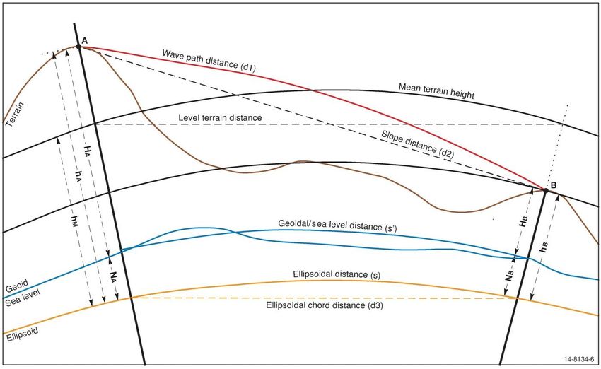
Intergovernmental Committee on Surveying and Mapping

Terms and definitions
 Symbol Definition Equation / Comment

 Ellipsoid semi-major axis

 Ellipsoid semi-minor axis = (1 − )

 −
 Flattening of the reference ellipsoid =

 1/ Inverse flattening or reciprocal flattening 1/

 −
 Third flattening
 +

 2 − 2
 First eccentricity of the reference ellipsoid √
 2

 2 − 2
 ′ Second eccentricity of the reference ellipsoid √
 2

 The radius of curvature at a point on an ellipsoid with respect to
 ρ
 the meridian through that point.

 The radius of curvature at a point on an ellipsoid with respect to

 the prime vertical through that point.

 Geodetic latitude; this is negative south of the equator.

 The angle that the normal to the ellipsoid at a point makes with the
 equatorial plane of the ellipsoid.

 A geodetic latitude differs from the corresponding astronomic
 latitude by the amount of the meridional component of the
 local deflection of the vertical.

 Geodetic longitude; positive measured eastwards from the
 Greenwich meridian.

 The angle between the plane of the local geodetic meridian and the
 Greenwich meridian.

 A geodetic longitude differs from the corresponding astronomic
 longitude by the amount of the prime vertical component of the
 local deflection of the vertical.

 0 Geodetic longitude of the central meridian

Geocentric Datum of Australia 2020 Technical Manual 7
Version 1.2
Intergovernmental Committee on Surveying and Mapping

 Geodetic longitude difference measured from the central meridian;
 − 0
 positive measured eastwards

 Azimuth; the horizontal angle measured from the meridian

 measured clockwise from true north.

 Ellipsoidal distance; the distance on the ellipsoid. Spheroidal

 distance is the same as an ellipsoidal distance.

 ′ Easting; positive measured eastwards from a central meridian

 ′ + 500,000 metres
 Easting measured from the false origin
 for MGA2020

 ′ Northing; negative measured southwards from the equator

 ′ + 10,000,000
 Northing measured from the false origin
 metres in the

 southern hemisphere
 for MGA2020

 Grid convergence; the angular quantity to be added algebraically to
 an azimuth to obtain a grid bearing. In the southern hemisphere,
 grid convergence is positive for points east of the central meridian = +
 (grid north is west of true north) and negative for points west of the
 central meridian (grid north is east of true north)

 Grid bearing; the angle between grid north and the tangent to the
 arc at the point. It is measured from grid north clockwise through
 360°

 Arc-to-chord correction; the angular quantity to be added = +

 algebraically to a grid bearing to obtain a plane bearing = + +

 Plane bearing; the angle measured clockwise through 360°,
 between grid north and the straight line on the grid between the
 ends of the arc formed by the projection of the ellipsoidal distance

 Plane distance is the straight-line distance on the grid between the =
 ends of the arc of the projected ellipsoidal distance. The difference Δ
 in length between the plane distance ( ) and the grid distance ( ) is tan =
 Δ
 nearly always negligible. Using plane bearings and plane distances, Δ = sin
 the formulae of plane trigonometry hold rigorously: Δ = cos

 0.9996 for MGA2020
 0 Central scale factor; the scale factor on the central meridian
 and UTM

Geocentric Datum of Australia 2020 Technical Manual 8
Version 1.2
Intergovernmental Committee on Surveying and Mapping

 Point scale factor; the ratio of an infinitesimal distance at a point on
 = =
 the grid to the corresponding distance on the ellipsoid

 Line scale factor; the ratio of a plane distance to the

 corresponding ellipsoidal distance . The point scale factor will in = ≈
 general vary from point to point along a line on the grid

 Ellipsoidal height; the distance of a point measured along the
 ℎ normal from the ellipsoid. Spheroidal height is the same as an
 ellipsoidal height

 Orthometric height; the height of a point above the geoid measured

 along the plumbline

 Height of a point above AHD

 Ellipsoid to quasigeoid separation

 Ellipsoid to AHD separation

 A three dimensional coordinate system (Cartesian) which has its
 , ,
 origin at (or near) the centre of the Earth.

 Reverse Azimuth =
 Meridian convergence; the change in the azimuth of a geodesic
 Forward Azimuth +
 Δ between two points on the ellipsoid.
 Meridian
 Convergence ± 180°

 Reverse grid bearing
 Line curvature; the change in grid bearing between two points on
 = Forward grid
 Δ the arc
 bearing + Line
 curvature ± 180°

 Meridian distance is the geodesic distance from the equator along
 the meridian, negative southwards

 Mean length of an arc of one degree of the meridian

 = /
 Meridian distance expressed as units

 Grid distance; the length measured on the grid, along the arc of the
 projected ellipsoid distance.

 Geometric mean radius of curvature √

Geocentric Datum of Australia 2020 Technical Manual 9
Version 1.2
Intergovernmental Committee on Surveying and Mapping

 Radius of curvature at a point in a given azimuth

 2 2 0 2 = 0 2

 2 2 at the mean latitude 0 2 at

 /
 Ratio of the ellipsoidal radii of curvature

 Rectifying radius

 ( 1 + 2 )
 Mean latitude
 2

 ′ Foot point latitude; the latitude for which the meridian distance
 = ′ / 0

 Parametric latitude

 Reduced latitude

Geocentric Datum of Australia 2020 Technical Manual 10
Version 1.2
Intergovernmental Committee on Surveying and Mapping 1 Introduction 1.1 Purpose of the Technical Manual The purpose of the Geocentric Datum of Australia 2020 (GDA2020) Technical Manual is to: define GDA2020; provide descriptions, transformation parameters and examples to assist with datum transformations between GDA2020, realisations of the International Terrestrial Reference Frame (ITRF) and historic Australian datums; provide descriptions and examples to assist with coordinate conversions between Earth-centred Cartesian, geodetic and map projected coordinates; provide descriptions and examples of coordinate computations; and define the Australian Height Datum (AHD) and AUSGeoid2020, and describe how to convert between ellipsoidal heights and AHD heights. 1.2 The Geocentric Datum of Australia 2020 Prior to the release of the GDA2020, the Geocentric Datum of Australia 1994 (GDA94) was the only Australian datum that used the acronym GDA. As a consequence, the acronym GDA was often used interchangeably with GDA94. When referring to any documents or software developed prior to the release of GDA2020, the reader can assume GDA refers to GDA94. 1.2.1 Terminology Table 1.1: GDA2020 terminology. Datum Geodetic Coordinate Set Grid Coordinates GDA2020 GDA2020 MGA2020 1.2.2 Definition Table 1.2: GDA2020 definition. Reference frame Epoch Ellipsoid Semi-major axis (m) Inverse flattening ITRF2014 2020.0 GRS80 6378137 298.257222101 1.2.3 Legal traceability of position and Australian Fiducial Network The National Measurement Institute (NMI) administers the National Measurement Act 1960 and has the authority to appoint legal metrology authorities to verify reference standards of measurement. Geoscience Australia is appointed as a Verifying Authority for Position. As a Verifying Authority for Position, Geoscience Australia can issue certificates of Geocentric Datum of Australia 2020 Technical Manual 11 Version 1.2
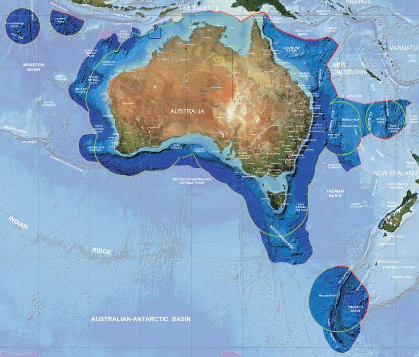
Intergovernmental Committee on Surveying and Mapping verification under Regulation 13 of the National Measurement Regulations 1999. These are commonly referred to as Regulation 13 Certificates. Regulation 13 Certificates provide coordinates and their uncertainty with respect to the Recognized-value standard of measurement of position (RVS) in Australia, which is the Australian Fiducial Network (AFN). The AFN was updated in October 2017 and includes 109 stations from the Australian Global Navigation Satellite System network which: are operated by Geoscience Australia or similar agency; are located on the Australian Tectonic Plate, within Australia’s jurisdiction and on a high quality survey monument; and have residuals less than 1 mm/yr relative to the Australian plate motion model (Section 3.3). To define GDA2020, International Terrestrial Reference Frame 2014 (ITRF2014) coordinates and velocities of the 109 AFN stations were mapped forward to the epoch of January 1, 2020 using the plate motion model (Section 3.3). GDA2020 is determined with respect to the RVS with crustal velocities and their uncertainties. These velocities enable coordinates to be mapped to any epoch. The list of 109 AFN stations including their coordinates and velocities, and the equation for coordinate conversion is shown in Appendix A. More information on Regulation 13 Certificates including the application process can be found on the Geoscience Australia website (http://www.ga.gov.au/scientific- topics/positioning-navigation/geodesy/regulation-13-certificates). Table 1.3: Verifying Authority for Position scope of accreditation and least uncertainty. Physical Quantity Range of Measurement Least Uncertainty (95%CI) Position Australia and its Territories 7 mm horizontal (horizontal & vertical) 15 mm vertical Note: “Least uncertainty” is synonymous with “best measurement capability”. It is the smallest uncertainty of measurement that can realistically be expected under ideal conditions. 1.2.4 GDA2020 extent The extent of the GDA2020 includes all the areas contained within Australia’s marine jurisdiction (within 200 nautical miles of Australia) and its external territories, and the areas of Australia’s continental shelf beyond 200 nautical miles as confirmed by the United Nations Commission on the Limits of the Continental Shelf. The areas include Cocos (Keeling) Islands, Christmas Island, Norfolk Island and Macquarie Island but excludes Heard-McDonald Islands and the Australian Antarctic Territory (AAT) as shown in Figure 1.1. The extent of GDA2020 is the same as the extent of GDA94. Geocentric Datum of Australia 2020 Technical Manual 12 Version 1.2
Intergovernmental Committee on Surveying and Mapping

Figure 1.1: The area shown in dark blue is the GDA2020 extent. The colours of the lines represent
different types of jurisdictional boundaries or proposed jurisdictional boundaries. For more information
on the type of boundary, please refer to http://www.ga.gov.au/metadata-
gateway/metadata/record/gcat_70362

1.3 Geodetic Parameter Registries
Internationally there are a number of geodetic registries that are relied upon as the source
of information for defining geodetic datums and the transformations between them. A
registry is a database of coordinate reference system information including ellipsoids,
units, datums, projections and transformations. Each database element is assigned a code
to identify it uniquely. The registry name, code number and type of registry element
provide a shorthand method for defining the relevant coordinate reference system
information.

For example, “EPSG::1168 Geodetic datum” refers to the defining elements of the
Geocentric Datum of Australia GDA2020 held in the EPSG registry.

1.3.1 EPSG Registry

The EPSG registry (http://www.epsg-registry.org/) is a reliable, freely available registry of
geodetic and transformation information. It is maintained on a “best effort” basis by the
Geomatics Committee of the International Association of Oil and Gas Producers (IOGP;

Geocentric Datum of Australia 2020 Technical Manual 13
Version 1.2
Intergovernmental Committee on Surveying and Mapping

previously known as the European Petroleum Survey Group or EPSG). It is updated on a
needs basis, which generally equates to two full release amendments per year.

Datum elements in this manual are identified by EPSG codes and registry element type
where they exist at the time of publication and the manual will be revised when additional
codes are available.

A number of organisations reproduce content from the EPSG registry but the IOGP site
http://www.epsg-registry.org/ is the only official EPSG dataset.

1.3.2 ISO Registry

The International Standards Organisation Technical Committee 211 Geographic
information / Geomatics (ISO/TC 211) is responsible for the ISO geographic information
series of standards. ISO/TC 211 is developing an ISO Geodetic Registry (ISO 19127) that will
ultimately replace the functions of the EPSG registry. Once ISO Registry codes are available
they will be referenced in future updates to this manual.

1.4 History of Australian datums
1.4.1 Early history

Between 1858 and 1966, geodetic surveys in Australia were computed on either a
jurisdiction (state or territory) or regional basis using more than four different spheroids
and as many as twenty coordinate origins.

The National Mapping Council (NMC), at its 23rd meeting in April 1965, adopted the
Geodetic Reference System 1967 (GRS 1967) ellipsoid, then recommended for general use
by the International Union of Geodesy and Geophysics, with the flattening term taken to
two decimal places. The NMC decided to call this spheroid the Australian National Spheroid
(ANS; see Table 1.6) (NMC, 1966).

1.4.2 Australian Geodetic Datum 1966

Re-computation and adjustment of all geodetic surveys in Australia on ANS were
commenced by the Division of National Mapping in June 1965. By 8 March 1966, all
geodetic surveys in Australia were re-computed and adjusted on the Australian Geodetic
Datum (AGD). This datum was subsequently adopted by the NMC on 21 April 1966, during
its 24th meeting in Melbourne, and was proclaimed in the Commonwealth Gazette No. 84
of 6 October 1966.

In 1966, the minor axis of the spheroid was defined as being parallel to the Earth's mean
axis of rotation at the start of 1962. In 1970 the NMC decided to adopt the Conventional
International Origin (CIO), previously known as the mean pole 1900.0-1906.0, for the
direction of the minor axis. The NMC decided that no change in the 1966 coordinates was
necessary. The AGD66 reference meridian plane of zero longitude was defined as being
parallel to the Bureau International de l'Heure (BIH) mean meridian plane near Greenwich.
This gave a value of 149° 00' 18.885” East for the plane contained by the vertical through
the Mount Stromlo photo zenith tube and the CIO. The position of the centre of the ANS is
defined by the following coordinates of Johnston Geodetic Station:

Geocentric Datum of Australia 2020 Technical Manual 14
Version 1.2
Intergovernmental Committee on Surveying and Mapping

Table 1.4: Johnston Geodetic Station coordinates.
 Geodetic Latitude 25° 56' 54.5515” South
 Geodetic Longitude 133° 12' 30.0771” East
 Spheroidal Height 571.2 metres

The size, shape, position and orientation of ANS were thus completely defined, and
together with the coordinates of the Johnston Geodetic Station, defined AGD66. The
coordinates for Johnston Geodetic Station were derived from astronomical observations at
275 stations on the geodetic survey distributed all over Australia. The spheroidal height
was adopted to be 571.2 metres, which was equal to the height of the station above the
geoid as computed by trigonometrical levelling in 1965.

Due to the almost complete lack of geoidal profiles at the time of the 1966 national
adjustment, it was then assumed that the geoid-spheroid separation was zero not only at
Johnston Geodetic Station but also at all other geodetic stations listed in this adjustment.
This assumption implied that every distance used in the 1966 adjustment was a geoidal or
sea level distance (assumed spheroidal distance).

A Universal Transverse Mercator (UTM) projection was associated with AGD66 and was
referred to as the Australian Map Grid (AMG66). The AGD66 and UTM projection, AMG66,
were adopted by all the States and Territories in Australia, particularly in support of the
national mapping program.

1.4.3 Australian Geodetic Datum 1984

Since 1966, there were several readjustments of the national geodetic survey. Each
readjustment was referred to as a Geodetic Model of Australia (GMA) and was identified
by the year in which the data set used in the readjustment was compiled. The adjustment,
GMA82, included satellite Transit Doppler, Satellite Laser Ranging (SLR), Electronic Distance
Measurement (EDM) tellurometer and Very Long Baseline Interferometry (VLBI)
observations.

Recognising the need for Australia to eventually convert to a geocentric geodetic datum,
the NMC, at its 42nd meeting in October 1984, resolved that the GMA82 adjustment would
be adopted as the first step in the conversion process. However, the Council also resolved
that members could use their discretion in the timing of the conversion process.

The GMA82 adjustment maintained AGD as originally defined by the combination of the
1966 coordinate set for Johnston Geodetic Station and the defining parameters for the
ANS. This led to the development of the Australian Geodetic Datum 1984 (AGD84)
coordinate set and associated UTM projection, known as the Australian Map Grid 1984
(AMG84).

In order to prevent any confusion arising with regard to the terminology to be used in
conjunction with the 1966 and GMA82 adjustments, the NMC adopted the following
definitions for general usage:
Table 1.5: Terminology used to differentiate between AGD66 and AGD84.
 Datum Australian Geodetic Datum
 Spheroid Australian National Spheroid
 1966 Coordinate Set Australian Geodetic Datum 1966

Geocentric Datum of Australia 2020 Technical Manual 15
Version 1.2
Intergovernmental Committee on Surveying and Mapping

 Australian Map Grid 1966
 1982 Adjustment GMA82
 1984 Adopted Coordinate Set Australian Geodetic Datum 1984
 Australian Map Grid 1984

Unlike the 1966 adjustment, the GMA82 adjustment is a truly spheroidal adjustment.
Therefore, any observations used in conjunction with the AGD84 coordinate set should first
be reduced to the ANS using the appropriate geoid-spheroid separation values in terms of
N = +4.9 metres at Johnston Geodetic Station.

NOTE: Not all jurisdictions adopted AGD84. Northern Territory, New South Wales,
Australian Capital Territory, Victoria and Tasmania chose to stay on AGD66.

1.4.4 Geocentric Datum of Australia 1994

To align the Australian datum to a global reference frame, Australia adopted the
Geocentric Datum of Australia 1994 (GDA94) and UTM projection the Map Grid of Australia
1994 (MGA94). At this time the recommended reference ellipsoid was also changed from
ANS to the Geodetic Reference System 1980 (GRS80) ellipsoid after it was adopted at the
XVII General Assembly of the International Union of Geodesy and Geophysics (IUGG) in
Canberra, Australia, 1979 as the recommended best-fit ellipsoid for the Earth (Moritz,
2000). GRS80 has its geometric centre coincident with the centre of the mass of the Earth
whereas the centre of the ANS lay about 200 m from the centre. Hence, the GDA94
coordinates of a point differ by about 200 metres (north-east) compared to AGD
coordinates.

In 1992, as part of an International Global Navigation Satellite System Service (IGS)
campaign (previously known as the International GPS Service), continuous GPS
observations were undertaken on eight geologically stable marks at sites across Australia,
which formed the Australian Fiducial Network (AFN). During this campaign, GPS
observations were also carried out at a number of existing geodetic survey stations across
Australia. These were supplemented by further observations in 1993 and 1994, producing
a network of about 70 well-determined Global Navigation Satellite System (GNSS) sites,
with nominal 500 km spacing across Australia. These sites are collectively known as the
Australian National Network (ANN).

The GPS observations at both the AFN and ANN sites were combined in a single regional
GPS solution in terms of the International Terrestrial Reference Frame 1992 (ITRF92) and
the resulting coordinates were mapped to a common epoch of 1994.0.

The positions for the AFN sites were estimated to have an absolute accuracy of about 2 cm
at 95% confidence level in the horizontal component (Morgan et al., 1996), while the ANN
positions are estimated to have an absolute accuracy of about 5 cm in the horizontal
component. The positions of the AFN sites were used to determine GDA94 and were
published in the Commonwealth of Australia Government Gazette on 6 September 1995.

On 4 April 2012, the AFN was updated to include 21 sites. The purpose of the update was
to improve its consistency with the most recent realisation of International Terrestrial
Reference System (ITRS) at the time (ITRF2008). The updated AFN coordinates were
adopted from ITRF2008 and subsequently transformed to GDA94 (i.e. ITRF1992 at epoch
1994.0) using the Dawson and Woods (2010) transformation parameters. For those

Geocentric Datum of Australia 2020 Technical Manual 16
Version 1.2
Intergovernmental Committee on Surveying and Mapping stations with multiple coordinate estimates in ITRF2008 the most recent coordinate estimate was adopted. 1.4.5 Geocentric Datum of Australia 2020 Since the realisation of GDA94, there have been significant developments in technology that provide ready access to accurate positioning systems. In the near future it is anticipated that GNSS will be capable of providing positioning services with centimetre accuracy in real-time to the mass market on mobile devices. Given that data from GNSS is referenced to a global reference frame, it is appropriate that the Australian datum be closely aligned to ITRF2014. GDA2020 is based on a realisation of the ITRF2014 (ITRF2014; Altamimi et al., 2016) at epoch 2020.0. The Geocentric Datum of Australia 1994 was based on the realisation of ITRF1992 at epoch 1994.0. Since then: due to plate tectonic motion, GDA94 coordinates have continued to diverge from ITRF92 coordinates. By 2020, the difference will be approximately 1.8 m; there have been many improvements and realisations of the ITRS which better define the shape of the Earth. For example, differences between ITRF1992 and ITRF2014 (on which GDA2020 is based) causes a ~9 cm change in ellipsoidal heights in Australia (GDA2020 heights are ~9 cm less than GDA94 ellipsoidal heights); and parts of the Australian crust have deformed (e.g. subsidence). These refinements to the reference frame and local scale distortions have not been reflected in changes to the Australian datum; some of which will begin to be noticeable to some users of positioning services. 1.4.5.1 Computation of GDA2020 coordinates GDA2020 coordinates were computed using a rigorous, 3D network adjustment of all available GNSS and terrestrial data from Commonwealth, state and territory jurisdictional archives. This adjustment enables the determination of GDA2020 coordinates and supports the computation of positional uncertainty and relative uncertainty between any survey control marks in Australia. The national GDA2020 adjustment was undertaken by Geoscience Australia with input from geodetic specialist representatives from all jurisdictional survey organisations. The national GDA2020 network adjustment involved a rigorous least squares adjustment of all data. In the past, adjustments were undertaken with higher order data being held fixed in lower order adjustments. This resulted in distortions in the datum that have become more apparent when compared with high accuracy GNSS data observed in ITRF2008 or ITRF2014 and transformed back to 1994 using a 7-parameter similarity transformation. By performing a single national rigorous adjustment these distortions have been reduced and relative uncertainty can be computed for any given points on the datum. The national GDA2020 network adjustment includes all available GNSS and terrestrial data from the jurisdictional archives, constrained using the Asia-Pacific Reference Frame (APREF) time series combination solution. This solution is calculated weekly by Geoscience Australia for approximately 450 APREF stations within Australia’s jurisdiction and it provides a link between ITRF2014 and GDA2020. The development of GDA2020 has also seen the creation of the National GNSS Campaign Archive stored at Geoscience Australia. Geocentric Datum of Australia 2020 Technical Manual 17 Version 1.2
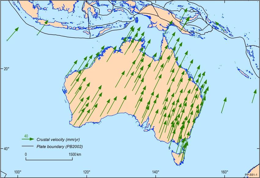
Intergovernmental Committee on Surveying and Mapping

 This archive contains all GNSS observations provided by state and territory jurisdictions
 greater than six hours duration. The data was processed (and will continue to be as new
 data is available) by Geoscience Australia to create a national high quality GNSS network.

 1.4.6 Summary of Australian horizontal datums

 A summary of the Australian datums is provided in Table 1.6. In some previous
 documentation, GDA and AGD have been documented as the name of the datum and the
 epoch has been appended to describe the coordinate set (e.g. AGD66). To avoid confusion,
 it is recommended that the epoch be appended when describing the name of the datum so
 users can differentiate between them (e.g. GDA94 and GDA2020). The EPSG codes for the
 datums are shown in Table 1.7.
 Table 1.6: Summary of the parameters of Australian datums.
 Geographic
 Grid Reference Ellipsoid / Semi-major Inverse
 Datum Coordinate
 Coordinates Frame Spheroid axis (m) Flattening
 Set
GDA2020 GDA2020 MGA2020 ITRF2014 GRS80 6378137.0 298.257222101
GDA94 GDA94 MGA94 ITRF1992 GRS80 6378137.0 298.257222101
AGD84 AGD84 AMG84 ANS 6378160.0 298.25
AGD66 AGD66 AMG66 ANS 6378160.0 298.25

 Table 1.7: EPSG codes of Australian datums.
 Geographic EPSG Code EPSG Code EPSG Code EPSG Code
 Datum Coordinate Geodetic Geodetic CRS Geodetic CRS Geodetic CRS
 Set Datum (Geocentric) (Geographic 3D) (Geographic 2D)
 GDA2020 GDA2020 1168 7842 7843 7844
 GDA94 GDA94 6283 4938 4939 4283
 AGD84 AGD84 6203 - - 4203
 AGD66 AGD66 6202 - - 4202

 1.5 Overview of the differences among GDA2020,
 ITRF2014 and GNSS reference frames
 1.5.1 GDA2020 and ITRF2014

 GDA2020 is aligned with ITRF2014 (Altamimi et al., 2016) at epoch 2020.00. ITRF2014 is
 the most recent realisation of a global network of accurate coordinates (and their
 velocities) maintained by the International Earth Rotation and Reference Systems Service
 (IERS) and derived from geodetic observations (VLBI, SLR, GPS and DORIS) (Seeber, 1993).

 On January 1 2020, ITRF2014 at epoch 2020.0 will coincide with GDA2020. From January 1
 2017 until January 1 2020, the difference between ITRF2014 coordinates (at the observed
 epoch) and GDA2020 coordinates will continually converge as the Australian tectonic plate
 moves 7 cm per year in a north-easterly direction. Until 2020, there will be an increasing
 convergence in the coordinates of GDA2020 and ITRF2014. From January 1 2020, there will
 be an increasing divergence in the coordinates of the GDA2020 and ITRF2014.

 Geocentric Datum of Australia 2020 Technical Manual 18
 Version 1.2
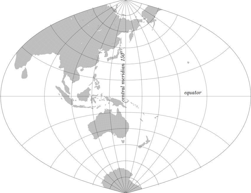
Intergovernmental Committee on Surveying and Mapping

1.5.2 World Geodetic System 1984

The World Geodetic System, of which the latest revision is WGS84 (G1762), is the datum
used by the GPS operated by the U.S. Department of Defense. The datum is defined and
maintained by the United States National Geospatial-Intelligence Agency (NGA). WGS84
has been revised several times since its conception and is at present aligned at the
centimetre level to ITRF2014 (NGA, 2014a). The WGS84 coordinates of tracking stations
used to compute the GPS broadcast orbit are adjusted annually for plate tectonic motion
to an epoch at the half year mark, e.g. WGS84 as used in the GPS broadcast orbit during
calendar year 2014 was ITRF2008 at 2014.5. Consequently, differences between the
ITRF2014 and WGS84 are negligible for most users.

For information on the reference systems of GLObal NAvigation Satellite System
(GLONASS), Galileo, BeiDou, Indian Regional Navigation Satellite System (IRNSS) and Quasi
Zenith Satellite System (QZSS), please refer to the United Nations Office of Outer Space
Affairs (UNOOSA, 2016).

1.6 Map Grid of Australia 2020 (MGA2020)
Geodetic coordinates (latitude and longitude) are represented on a map or chart, by
mathematically projecting them onto a two-dimensional plane. The Transverse Mercator
(TM) projection is a conformal mapping of geodetic coordinates from the ellipsoid onto a
plane where the equator and central meridian remain as straight lines and the scale along
the central meridian is constant while meridians and parallels are projected as complex
curves (Figure 1.2).

Figure 1.2: Transverse Mercator projection with central meridian of 150 degrees.

Geocentric Datum of Australia 2020 Technical Manual 19
Version 1.2
Intergovernmental Committee on Surveying and Mapping

The TM projection is useful to map regions with large extents of latitude; however,
distortions increase rapidly away from the central meridian.

The UTM system (Table 1.8) uses the TM projection and attempts to overcome this
limitation by dividing the Earth into 60 zones, each with a width of 6° of longitude. A
central meridian is placed in the middle of each longitudinal zone. As a result, within a
zone nothing is more than 3° from the central meridian and therefore locations, shapes
and sizes and directions between all features are very accurate.

The true origin for each zone is the intersection of the equator and the central meridian,
but a false origin is often used to avoid negative coordinates (Figure 1.3).

Figure 1.3: Relationship between geographic coordinates and projected coordinates.

Table 1.8: UTM system parameters

Parameter Value

Longitude of initial central meridian (Zone 1) 177 degrees west longitude
Zone width 6 degrees
Central scale factor 0.9996
False Easting 500,000 m
False Northing (in the southern hemisphere) 10,000,000 m

Geocentric Datum of Australia 2020 Technical Manual 20
Version 1.2
Intergovernmental Committee on Surveying and Mapping

The UTM system has been used with the GRS80 ellipsoid and GDA2020 latitudes and
longitudes to define Map Grid of Australia 2020 (MGA2020).

The Krueger n-series or Krueger -series formulae are used to convert between UTM (or
MGA2020) coordinates and geographic coordinates and vice versa (Section 4.1).

Geocentric Datum of Australia 2020 Technical Manual 21
Version 1.2
Intergovernmental Committee on Surveying and Mapping

2 Reference frame and coordinate system
 fundamentals

2.1 Coordinate systems
2.1.1 Cartesian

The Cartesian coordinate system is a three-dimensional system with positions referenced
to orthogonal axes with the origin at the centre of the reference ellipsoid (Figure
2.1). The -axis is in the direction of the rotational axis of the ellipsoid of revolution, the
 − plane is, by convention, the Greenwich meridian plane (the origin of longitudes) and
the − plane is the equatorial plane of the ellipsoid (the origin of latitudes) (Gerdan and
Deakin, 1999).

2.1.2 Geographic

The geographic coordinate system is an ellipsoidal coordinate system. A specific type of
geographic coordinate system is a geodetic coordinate system; a three-dimensional system
with positions referenced using geodetic latitude , geodetic longitude and ellipsoidal
height ℎ (Figure 2.1). Geodetic latitude and longitude are, by convention, measured
relative to the equator and prime meridian plane respectively.

Equations 1-3 can be used to convert from Cartesian coordinates to geodetic coordinates.

 tan = (1)

 ( (1− )+ 2 sin3 )
 tan = (2)
 ((1− )( − 2 cos3 ))

 ℎ = cos + sin − √(1 − 2 sin2 ) (3)

where

 = √( 2 + 2 ) (4)

 tan = ( ) [(1 − ) + ( 2 )] (5)

 = √( 2 + 2 ) (6)

 2 = 2 − 2 (7)

Geocentric Datum of Australia 2020 Technical Manual 22
Version 1.2
Intergovernmental Committee on Surveying and Mapping

Figure 2.1: Relationship between Cartesian and geographic coordinate systems.

The following formulae can be used to convert from geodetic coordinates to Cartesian
coordinates.

 = ( + ℎ) cos cos (8)

 = ( + ℎ) cos sin (9)

 = {(1 − 2 ) + ℎ} sin ( 10 )

where

 = ( 11 )
 {√(1− 2 sin2 )}
 2 = 2 − 2 ( 12 )

 ℎ = + ( 13 )

Further reading on geographic to Cartesian conversion techniques including some well
suited for efficient use in software can be found in Gerdan and Deakin (1999).

Geocentric Datum of Australia 2020 Technical Manual 23
Version 1.2
Intergovernmental Committee on Surveying and Mapping 2.1.3 Local The local reference system is a three-dimensional system with positions referenced using orthogonal axes with the origin on or above a point on the ellipsoid, and orientation with respect to a local geodetic meridian (Fraser, Leahy and Collier, 2017; Figure 2.2). Vectors in the Cartesian reference frame can be represented in the local reference frame as Δ = [ Δ ] ( 14 ) Δ A vector in the local reference frame is related to the Cartesian reference frame by = ( 15 ) where is the rotation matrix with origin at latitude and longitude − sin − sin cos cos cos [ cos − sin sin cos sin ] ( 16 ) 0 cos sin Figure 2.2: The local coordinate reference system. Geocentric Datum of Australia 2020 Technical Manual 24 Version 1.2
Intergovernmental Committee on Surveying and Mapping

2.2 Transformations between reference frames
A similarity transformation (also known as a conformal transformation) can be used to
transform coordinates (or vectors) from one geodetic reference frame (A) to another (B).
At the computational level this transformation is performed on the Cartesian
coordinates. The 14-parameter similarity transformation (Equation 17) is the 7-parameter
transformation (3 translations , 3 rotations and scale ) with an additional
7 parameters used to describe the rates of change of the translation ̇ ̇ ̇ , rotation
 ̇ ̇ ̇ and scale ̇ in time and eliminating the negligible terms (Altamimi et al., 2002). This
allows for transformation between datums with data sets at any given epoch where 0 is
the reference epoch. The translations and their rates are expressed in m and m/yr,
respectively. The rotation and their rates are expressed in radians and radians/yr,
respectively. The scale is unit-less and the scale rate is expressed in yr-1. Parameters ′ ′
 ′ are the transformed coordinates.

 ′ + ̇ ( − 0 )
 ( ) = ( + ̇ ( − 0 ) ) + (1 + + ̇ ( − 0 ))
 ′

 ′ + ̇ ( − 0 )

 1 + ̇ ( − 0 ) − − ̇ ( − 0 )
 (− − ̇ ( − 0 ) 1 + ̇ ( − 0 ) ) ( ) ( 17 )
 + ̇ ( − 0 ) − − ̇ ( − 0 ) 1

2.2.1 Rotation matrix sign convention

There are two different ways of applying the sign conventions for the rotations. In both
cases a positive rotation is an anti-clockwise rotation, when viewed along the positive axis
towards the origin but:

 1. The IERS assumes the rotations to be of the points around the Cartesian axes,
 while;

 2. The method historically used in Australia assumes the rotations to be of the
 Cartesian axes around the points.

Although these two conventions exist, to enforce the property that all rotations describe
anticlockwise rotation as positive when viewed along the axis towards the origin, the
rotation of the coordinate axes around the points should be a skew-symmetric matrix with
the opposite sign to the rotation of the point/s around the coordinate axis.

The transformation parameters in the GDA2020 Technical Manual adhere to the Australian
convention. Due to the potential for confusion, it is advisable to ensure that the
conventions used in software are well understood and tested against the sample data
supplied in Section 3 of this manual.

Geocentric Datum of Australia 2020 Technical Manual 25
Version 1.2
Intergovernmental Committee on Surveying and Mapping

3 Coordinate transformation
Coordinate transformation is the process of changing coordinates from one reference
frame to another. Options for the transformation of coordinates to, and from, GDA2020,
are transformation parameters and transformation grids.
Table 3.1: Quick reference guide for assistance with transformations.

From To Section
GDA94 GDA2020 3.1, 3.2
ITRF2014 GDA2020 3.3
AGD66/84 GDA2020 3.4
ITRF (historic) GDA2020 3.5
MGA94 MGA2020 3.6

3.1 GDA94 to GDA2020 transformation parameters
The 7-parameter similarity transformation (Equation (18)) is also known as a conformal
transformation and accounts for the difference in scale, rotation and translation between
two reference frames. In this section, the parameters are shown to transform between
GDA94 and GDA2020. The official GDA94 to GDA2020 7 transformation parameters and
associated uncertainties (Table 3.2) were computed using 18 GNSS CORS common to both
the GDA94 RVS and the GDA2020 RVS. The GDA94 RVS (from 2011) had 21 AFN stations.
GNSS CORS located at Cocos Island (COCO), Christmas Island (XMIS) and Macquarie Island
(MAC1) were excluded from the computation due to earthquake deformation.

 ′ 1 −
 2020 94
 ′
 ( 2020 ) = ( ) + (1 + ) (− 1 ) ( 94 ) ( 18 )
 ′
 2020 − 1 94

Table 3.2: Transformation parameters for GDA94 to GDA2020 along with the one-sigma uncertainties
(1σ). Units are in metres for the translation, parts-per-million for scale, and arcseconds for rotations.

 0.06155 -0.01087 -0.04019 -0.009994 -0.0394924 -0.0327221 -0.0328979
uncertainty 0.0007 0.0006 0.0007 0.00010 0.000011 0.000010 0.000011

The parameters to transform from GDA2020 to GDA94 can be computed by multiplying the
values in Table 3.2 by -1.

3.1.1 Example: GDA94 to GDA2020 (7–parameter
 transformation)

GDA94 coordinates of Alice Springs (ALIC)
 Latitude (DMS) Longitude (DMS) Ellipsoidal Height (m)
 -23° 40’ 12.446019” 133° 53’ 07.847844” 603.3466

Geocentric Datum of Australia 2020 Technical Manual 26
Version 1.2
Intergovernmental Committee on Surveying and Mapping

 Latitude (DD) Longitude (DD) Ellipsoidal Height (m)
 -23.6701239 133.8855133 603.3466

 X Y Z
 -4052051.7643 4212836.2017 -2545106.0245

GDA2020 coordinates of Alice Springs (ALIC)
 X Y Z
 -4052052.7379 4212835.9897 -2545104.5898

 Latitude (DMS) Longitude (DMS) Ellipsoidal Height (m)
 -23° 40’ 12.39650” 133° 53’ 07.87779” 603.2489

 Latitude (DD) Longitude (DD) Ellipsoidal Height (m)
 -23.6701101 133.8855216 603.2489

Difference (GDA2020 – GDA94)
 Latitude Longitude Height (m)
Alice Springs (ALIC) 0.04952" 0.02995" -0.0977

 N (m) E (m) U (m)
Alice Springs (ALIC) 1.5236 0.8487 -0.0977

3.2 Transformation Grids
3.2.1 Overview

Transformation grids provide users of spatial data with a simple and nationally consistent
method to transform data between datums. The transformation grids are National
Transformation version 2 (NTv2) files of binary grid shift (.gsb) format and are the
preferred method for transforming between Australian datums. The transformation grids
Table 3.5 and 3.6) are available from the ICSM GitHub repository (https://github.com/icsm-
au/transformation_grids)

NOTE: The NTv2 format does not store ellipsoidal height information and therefore cannot
be used to transform the heights of data from one datum to the other. To transform
heights it is recommended that you convert your data from latitude, longitude, height
to earth-centred Cartesian coordinates using equations 8-10, apply the 7-parameter
transformation from GDA94 to GDA2020 (Table 3.2) and then convert back to using

Geocentric Datum of Australia 2020 Technical Manual 27
Version 1.2
Intergovernmental Committee on Surveying and Mapping equations 1-3. This step is shown in the similarity transformation spreadsheet (Section 3.7.2). 3.2.2 Types of transformation grids Two types of GDA94 – GDA2020 transformation grids have been developed: Conformal: predominantly plate tectonic motion (~1.8 m NNE) Conformal + Distortion: includes regional distortion The difference between GDA94 and GDA2020 coordinates is comprised of a conformal transformation component primarily due to plate tectonic motion (Figure 3.1), and an irregular (non-conformal) distortion component. The distortion component is attributable to several second-order effects, such as an improved realisation of the global reference frame over time; irregular ground movement since GDA94 was established; and a lack of rigour in the computation of GDA94. These effects vary in magnitude and direction around the country and can be as large as ~0.5 m. The combined conformal and distortion grids model both the conformal transformation (i.e. translation, rotation and scale) and distortion components of the differences in the datums. In the case of GDA94 to GDA2020, the distortion component is caused by the different strategies used by state and territories to propagate GDA94 coordinates onto ground survey control mark networks from the AFN and surface movement of parts of the Australian crust. The magnitude of the distortion varies between jurisdictions and can be in the order of decimetres. The GDA94 - GDA2020 conformal only transformation grid delivers the same result as the 7-parameter similarity transformation (Section 3.1). It has been developed at the request of some software providers who are moving towards the use of grids as the preferred method of geodetic transformation in selected software platforms. A particular example of its application would be for users who may be using GDA94 coordinates which were observed in ITRF2008/2014 and transformed back to GDA94 (e.g. CORS network operators) using a 7-parameter similarity transformation. These coordinates are not impacted by distortion in the realisation of the GDA94 datum and the use of the conformal and distortion transformation grid would actually introduce distortion, not remove it. The appropriate NTv2 transformation grid to use differs between jurisdictions and the Positional Uncertainty (or accuracy) of the dataset being transformed. Please refer to Table 3.4 for recommendations. Geocentric Datum of Australia 2020 Technical Manual 28 Version 1.2
Intergovernmental Committee on Surveying and Mapping

Figure 3.1: The difference between GDA94 and GDA2020 coordinates is primarily due to plate tectonic
motion.

Geocentric Datum of Australia 2020 Technical Manual 29
Version 1.2
Intergovernmental Committee on Surveying and Mapping

3.2.3 Development of transformation grids

The GDA94 – GDA2020 grids were developed using over 170,000 points at which both GDA94
and GDA2020 coordinates were available. The differences that remain after the conformal
component is removed, is the distortion component. In some regions the distortion
component is regular (Figure 3.2a) with a similar magnitude and direction, while in other
cases it is irregular (Figure 3.2b) with a different magnitude and / or direction. In regions with
an irregular distortion component, the transformation grid will be less reliable.

Figure 3.2: a) conformal (green) and distortion (red; high reliability) components of the transformation
grids; b) low reliability; c) the grid has a latitude component and longitude component.

After removing the conformal component, a least squares prediction was used to compute
the distortion in latitude (∆φ) and longitude (∆λ) on a regular 1’ grid (Figure 3.2c). The
conformal component is then added back to each grid point to complete the conformal +
distortion grid. For further information on the development of transformation grids, refer
to Collier (2002).

3.3 Plate motion model (ITRF2014 to GDA2020)
The plate motion model enables the transformation of coordinates (or vectors) from
ITRF2014 to GDA2020 and vice versa. The model was derived using 109 ARGN and AuScope
GNSS CORS which were used to define the RVS.

Geocentric Datum of Australia 2020 Technical Manual 30
Version 1.2
You can also read