Group B 2019 Copyright 2018 International Code Council, Inc.
←
→
Page content transcription
If your browser does not render page correctly, please read the page content below
Group B 2019           Copyright © 2018 International Code Council, Inc.

                    BCAC Structural WG Items
                    October 2-3, 2018 Meeting

IBC 15-1 Applicability of SBCCI SSTD 11-97

1504.2 Wind resistance of clay and concrete tile. Wind loads on clay and concrete
tile roof coverings shall be in accordance with Section 1609.5.

      1504.2.1 Testing. Testing of concrete and clay roof tiles shall be in accordance
      with Sections 1504.2.1.1 and 1504.2.1.2.

            1504.2.1.1 Overturning resistance. Concrete and clay roof tiles shall be
            tested to determine their resistance to overturning due to wind in
            accordance with Chapter 15 and either SBCCI SSTD 11 or ASTM C1568.

            1504.2.1.2 Wind tunnel testing. Where concrete and clay roof tiles do
            not satisfy the limitations in Chapter 16 for rigid tile, a wind tunnel test
            shall be used to determine the wind characteristics of the concrete or clay
            tile roof covering in accordance with SBCCI SSTD 11 and Chapter 15.

Reason:

                                                                               1|Page
Group B 2019         Copyright © 2018 International Code Council, Inc.

IBC 23-1 Clarification of lumber shrinkage
Revise as follows:

2303.7 Shrinkage effects. Where lumber is fabricated in a green
condition, the design shall consider consideration shall be given in design
to the possible the vertical effect of shrinkage due to cross-grain
dimensional changes considered vertically which may occur in lumber
fabricated in a green condition.

Reason: Correct poorly worded requirement.

                                                                     2|Page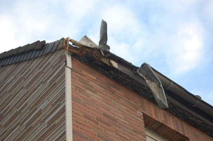
Group B 2019   Copyright © 2018 International Code Council, Inc.

IBC 15-2/IRC 9-1 Reference to manufacturer’s
installation instructions

                                                        3|Page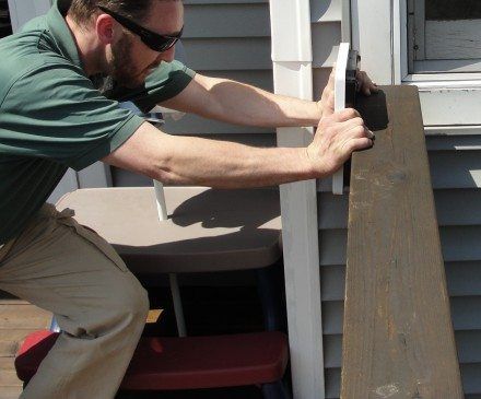
Group B 2019              Copyright © 2018 International Code Council, Inc.

IRC 6-1 Notching and boring classifications
R602.6 Drilling and notching of studs. Drilling and notching of studs shall be in
accordance with the following:

1. Notching. Any A stud in an exterior wall or bearing partition shall not be permitted to
be cut or notched to a depth not exceeding 25 percent of its depth width. Studs in
nonbearing partitions shall not be permitted to be notched to a depth not to exceed
exceeding 40 percent of a single stud depth width.

2. Boring. Drilling. Any stud shall be permitted to be bored or drilled, provided that the
diameter of the resulting hole is not more than The diameter of bored holes in studs
shall not exceed 60 percent of the stud depth width, the edge of the hole shall be is not
more less than 5/8 inch (16 mm) to from the edge of the stud, and the hole is shall not
located in the same section as a cut or notch. Where the diameter of a bored hole in a
stud located in exterior walls or bearing partitions drilled is over 40 percent, and up to
60 percent such stud shall be doubled with and not more than two successive
doubled studs shall be so bored. See Figures R602.6(1) and R602.6(2).

    Exception: Use of Where approved stud shoes is permitted where they are
    installed in accordance with the manufacturer’s recommendations instructions.

IRC R602.6 (2) Drilling. Any stud shall be permitted to be bored or drilled, provided
that the diameter of the resulting hole is not more than 60 percent of the stud depth
width, the edge of the hole is not more less than 5/8 inch (16 mm) to from the edge of
the stud, and the hole is not located in the same section as a cut or notch.

Reason: IMC 302.3.3, IPC C101.3, IFGC 302.3.4 sections were changed in this manner last
cycle. The current text uses the word width, when actually it is the depth that is meant. The
depth of a stud is the plane in which a hole is bored. Holes are not bored in the width (1 ½
inches) of a stud. This revision also gets rid of unenforceable permissive language. The current
text says that any stud is permitted to be notched to a depth not exceeding 25%. This is stating
a permitted limit; not a mandatory limit. A highway speed limit is not permitted to be 55 miles per
hour, rather it is an absolute limit of 55. If the stud is permitted to be notched to not exceed
25%, then it also permitted to be notched to not exceed other percentages. Lastly, this proposal
corrects a flaw where the text said that the edge of the hole cannot be more than 5/8 inch to the
edge of the stud. The intent is exactly the opposite. The edge of the hole must not be less than
5/8 inch to the edge of the stud.

Cost Impact: This proposal will not increase the cost of construction.

                                                                                        4|Page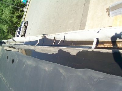
Group B 2019             Copyright © 2018 International Code Council, Inc.

IRC 9-1 Ice Shield clarifications (Chuck Bajnai)
Ice barrier is required in numerous places in Chapter 9 of the IRC –
Would it be required on the perimeter edge of a porch? (Shed roof or gable roof)
Would it be required on the perimeter edge of a screen porch?
Would it be required on the perimeter edge of an attached garage that does not have
habitable space above?
I think this section is very misleading, and if I were not retiring in 2018, I would rewrite
the sections to add clarity to the application.

I would like to offer the following code change proposal:

R905.17.4 and others:
“In areas where there has been a history…and extend from the lowest edges of all roof
surfaces to a point not less than 24 inches inside the exterior wall lines of the building.
  Exception 1: Ice shield is not required on the roof of a porch or roof overhangs
exceeding 36 inches. (the actual length of 36” is academic to the argument and can be
any length the BCAC thinks is justifiable).
  Exception 2: Ice shield is not required on the roof of an attached garage which has
no habitable attic above it.
  Exception 3. Detached accessory structures that do not contain conditioned floor
area, or a habitable attic above it.

As an alternative code change proposal:
R905.17.4
Delete all text and replace it with
Ice shield and drip edge shall be installed when the roofing manufacturer’s instructions
require them.

Reason: Issue 1: Ice shield is required at eaves adjacent to heated spaces because of
freeze and thaw cycles.
Therefore where there is no heat transfer to cause melting, then ice shield would not
serve any purpose.
Issue 2: The code says “from the lowest edges of all roof surfaces…” So if I had a roof
extend from the house over an 8’ wide porch, then the ice shield would have to start at

                                                                                     5|Page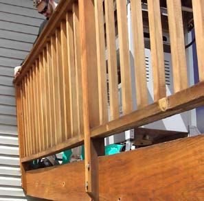
Group B 2019            Copyright © 2018 International Code Council, Inc.

the lowest edge of the eave and carry all the way up to the house plus 24 inches (total
of about 10’). Does that make sense from the physical reality of the problem.
In my humble opinion, it is not needed at the edges of porches, or attached garages
without habitable space above.

                                                                               6|Page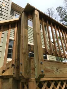
Group B 2019                Copyright © 2018 International Code Council, Inc.

IRC 3-1 Guard clarifications
The Deck Code Coalition (DCC) finds itself in a black hole and looks for ICC guidance. There was
overwhelming support from building officials at the Public Comment Hearings in Kansas City last fall with
regards to RB211 – Deck Guards, but the voting members balked at the code proposal and voted it
down. This leaves deck builders and building officials in a conundrum: To what design load do we
design deck guards? This vacuum was created by vague language in Table R301.5. In order to meet the
January, 2019 code change submittal deadline, we are soliciting your help in aiming several questions to
the right ICC committee(s).

BASIC QUESTION FOR ICC: What should a deck builder provide the
building official to substantiate that a guard system passes IRC code?
Note: We are discussing guards and NOT handrails.

                                                                                             7|Page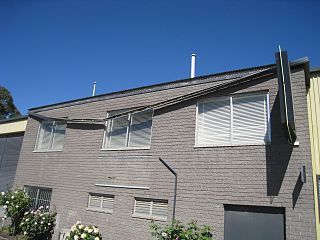
Group B 2019                 Copyright © 2018 International Code Council, Inc.

To get a clearer understanding of the question, I will rewrite the question with several smaller
questions.

    •   How is a building official to interpret the 200# requirement?
    •   Should the building official expect the deck guard system to pass a 200# test, a 400# test or a
        500# test.
    •   How is the “200# applied in any direction” to be verified?

Point 1: Deck builders and building officials uncertain

For too many years, without evidence of compliance, most building officials have allowed just about any
deck guard pass muster, and the deck builders have done nothing to stop them.

The rejection of ICC code change proposal RB211-2018 by the voting membership said they preferred no
help as to too much help, i.e. decks are safe enough the way they are build today. This declaration
offers no guidance for conscientious building officials and inspectors as to whether a constructed deck
guard complies with Table R301.5 or not. Short of the deck builder testing every deck to some
undefined testing method and undefined factor of safety in every direction, there is nothing prescriptive
in the IRC which can substantiate compliance to the building official.

Point 2: Table R301.5 is too vague

Table R301.5 appears to be a homeowner’s way of describing the intended loading condition – not
necessarily the way an engineer might describe the loading condition; see footnote h for comparisons
where the factor of safety is clearly stated.

So the problem with Table R301.5 is how the 200# is to be interpretted? The Loferski, Albright and
Woeste paper (see attachment) called the 200# load as the “code required design load”. Others call it a
“working load”, or an “actual load”. Did the authors of Table R301.5 intend the 200# to be THE actual,
working, verifiable load or did they intend something else?

Point 3: Testing

The purpose of the IRC is to provide affordable, time-tested, prescriptive, design standards to ensure
safety for all users. In the case of deck guards, the language says “200# applied in any direction”. It does
not say “assume ASD”, or assume LRFD”. There are no prescriptive details in the code which have
proved to be code compliant, i.e. you cannot use the eyeball test to determine if it is code compliant.

On the other hand, the IBC, Chapter 17 offers three methods of determining compliance:

    1. through design
    2. in-situ testing

        1709.3.2 says in-situ load testing: “…test load shall be equal to two times the unfactored
        design load. The test load shall be left in place for a period of 24 hours.”

    3. lab testing

        1710.3.1 says preconstruction load testing: “The allowable superimposed design load shall be
        taken as the lesser of

                                                                                                8|Page
Group B 2019                  Copyright © 2018 International Code Council, Inc.

        1. The load at the deflection limitation…

        2. The failure load divided by 2.5.

        3. The maximum load applied divided by 2.5.

But assuming for a moment that a factor of safety would be universally accepted, there are no ASTM
standards for how to test wood guards. All of the existing ASTM standards deal with steel or plastic
wood guard systems – and those only test in the outward
and downward directions.

Carrying that thought forward, building officials and deck
builders are looking for guidance. If deck builders have to
test each deck with in-situ test, what is the standard which
they have to prove:

        200# - built in the field

        400# - built in the field

        500# - built in the field.

To get the deck builder and building official out of this
conundrum, how does he show compliance to the building
official:

    •   In-situ testing by the deck builder or 3rd party testing agency? Expensive, time consuming
    •   Prescriptive details in the IRC? The ICC membership voted down details in RB211-2018.
    •   Ignore the problem? Been doing this forever.
    •   Rewrite the requirement in Table R301.5? ICC committee turned that idea down,
    •   Use existing test results to create new prescriptive details?
    •   Do they in fact have to test in the field for 24 hours? Is that 24 hours in each direction? Even the
        lab testing protocol only make them test in outward and downward directions.

Recognizing that the IRC is based on historical performance, can you give an opinion on the pictured
detail. According to the Loferski, Albright and Woeste paper, this guard system was capable of resisting
237# of outward load in the lab- no testing was done on downward load. This method has been used
for years around the country and accepted as meeting the 200# code requirement by building officials.
It is comprised of (2) ½” diameter thru bolts with washers into a 2x8 band board.

                                                                                                9|Page
Group B 2019 Copyright © 2018 International Code Council, Inc.
Point 4: Safety
The deck failures we have seen and read about in the news are based on two problems:
• Attachment of the deck to the house
• Improper maintenance.
There is very limited evidence that deck failures occur at the guard system. Therefore we need to come
up with something more logical than 400# or 500# test in all directions. It’s great that ASCE-7 has had
this criteria for several decades now, but it appears to be an expensive, and overly protective, not
justifiable burden on all deck builders. ICC membership has clearly told us that they don’t want to
require the deck builders to pony up with the details the DCC developed or the proprietary details that
some hardware companies are proposing as “best practices”.
Point 5: Cost
There is another underlying factor that plays a major role in this whole discussion – cost: extra time and
materials, extra hardware, extra testing. Professional deck builders have already given us feedback as to
what they think about cost of our proposed details in RB211 – not to mention how they would react if
we now required testing in-situ of each deck. How are the thousands of weekend warriors who build
their own decks going to construct and test their decks?
Conclusion
Let’s consider a continuum for where deck guard strength may lie:
0# ___________________200#_______________________________________________500#
Membership wants ICC Code Committee
wants
• Inexpensive
• Easy to build • Complies with IBC,
• Passes eyeball test ASCE-7
• Verifiable
The DCC tried two approaches for the 2018 IRC.
1. We proposed lowering the requirements in Table R301.5 to 200# outward and downward and
50# upward and inward. Proposal failed because the committee and engineers thought the
standards in IBC and ASCE-7 were long standing and appropriate.
2. The DCC proposed 5 prescriptive details which passed the engineering design methodology but
ICC membership turned them down because they were too expensive, burdensome and
perceived as overly conservative.
The DCC is interested in getting your opinion and direction so we can draft language and details which
offer the building officials, plan reviewers, inspectors, contractors and deck builders a way to visually
determine compliance at whatever load we all can agree on.
Thank you, Chuck Bajnai, Chairman of the Deck Code Coalition
10 | P a g eGroup B 2019 Copyright © 2018 International Code Council, Inc.
IBC 17-1 Special inspections structural wood
windforce-resisting system (Gary Ehrlich)
During a Structural WG call for the TWB, it was noted there were questions about
changes the TWB had proposed to Section 1705.11.1 and 1705.12.2 (below) modifying the long-standing
exceptions from special inspections. Specifically, how the change was specific to CLT and mass timber,
versus possibly having an impact on non-mass-timber products.
I suggested taking the proposed language to BCAC for consideration as a Group B item. I also offered to
champion it both as a BCAC member and possible (if not probable) chair of the BCAC Structural TG.
Section 1705.11.1 Structural Wood
Revise as follows:
1705.11.1 Structural wood. Continuous special inspection is required during field gluing operations of
elements of the main windforce-resisting system. Periodic special inspection is required for nailing,
bolting, anchoring and other fastening of elements of the main windforce-resisting system, including
wood shear walls, wood diaphragms, drag struts, braces and hold-downs.
Exception: Special inspections are not required for wood shear walls, shear panels and
diaphragms, including nailing, bolting, anchoring and other fastening to other elements of the
main windforce-resisting system, where the lateral resistance is provided by structural sheathing
and the fastener spacing of the sheathing is more than 4 inches (102 mm) on center.
Section 1705.12.2 Structural Wood
Revise as follows:
1705.12.2 Structural wood. For the seismic force-resisting systems of structures assigned to Seismic
Design Category C, D, E or F:
1. Continuous special inspection shall be required during field gluing operations of
elements of the seismic force-resisting system.
2. Periodic special inspection shall be required for nailing, bolting, anchoring and other
fastening of elements of the seismic force-resisting system, including wood shear walls,
wood diaphragms, drag struts, braces, shear panels and hold-downs.
Exception: Special inspections are not required for wood shear walls, shear panels and
diaphragms, including nailing, bolting, anchoring and other fastening to other elements of the
seismic force-resisting system, where the lateral resistance is provided by structural sheathing
and the fastener spacing of the sheathing is more than 4 inches (102 mm) on center.
11 | P a g eGroup B 2019 Copyright © 2018 International Code Council, Inc.
SPRI’s (Amada Hickman) 2019 - Group B Proposal Concepts
For BCAC’s Review and Comment
(March 13-14, 2018 Face-to Face meeting)
IBC 15-3 – Coping
Revise language as follows:
1503.3 Coping. Parapet walls shall be properly coped with noncombustible,
weatherproof materials of a width not less than the thickness of the parapet wall.
Exception: Roofing system assemblies where the roof covering membrane is
installed to extend and wrap over parapet walls at the perimeter that are less than 30
inches (762 mm) and down to the exterior side of the wall.
Sept 11, 2018 meeting notes
Alternative language (Amanda and Mike)
1503.3 Parapet walls Coping. Parapet walls shall be properly coped with
noncombustible, weatherproof materials of a width not less than the thickness of the
parapet wall.
Reason:
Section 705.11.1 of the IBC for Parapet Construction, requires that parapet walls be
not less than 30 inches. This proposal only applies to parapet walls at the perimeter
that are less than 30 inches. This language will allow a greater variety of options for
waterproofing the parapet wall. This will also provide additional options for
maintaining a continuous air barrier. For example, the roof membrane could be used
to wrap the top of the parapet wall and extend down the exterior side of the wall. The
membrane could then be tied into the wall air barrier system.
Cost Impact:
The code change proposal will not increase or decrease the cost of construction.
No additional materials or detailing will be required based on this code change
proposal; therefore it will not increase the cost of construction.
12 | P a g eGroup B 2019 Copyright © 2018 International Code Council, Inc.
IBC 15-4 – Edge Securement
Revise language as follows:
1504.5 Edge securement for low-slope roofs. Metal edge systems, except
gutters, installed on low-slope built-up, modified bitumen and single-ply roof
systems, metal edge securement, except gutters, shall be designed and installed for
wind loads in accordance with Chapter 16 and tested for resistance in accordance
with Test Methods RE-1, RE-2 and RE-3 of ANSI/SPRI ES-1, except basic design
wind speed, V, shall be determined from Figures 1609.3(1) through 1609.3(8) as
applicable.
Reason:
This proposal is intended to clarify that regardless if the roof membrane is either
independently or dependently terminated, the edge metal system needs to be
properly tested to the appropriate standard. Metal edge systems prevent water
infiltration, and in many cases to also secure the roof membrane. Loss of the edge
system or components of the edge system during a high wind event could allow for
water infiltration even if the roof membrane remains secure. Furthermore, any
component of the edge system that becomes disengaged during a high wind event
will become a projectile that can damage the roof membrane and other building
components (windows, doors, walls, etc.), and possibly injure people. Therefore,
metal edge systems should be tested per ES-1 whether they secure the membrane
or not.
Cost Impact:
The code change proposal will not increase or decrease the cost of construction.
This proposal just clarifies that this test applies to edge metal regardless of
installation method.
13 | P a g eGroup B 2019 Copyright © 2018 International Code Council, Inc.
IBC 15-5 – Gutter Securement
Add new language as follows:
1504.5.1 Gutter securement for low-slope roofs. External gutters installed on low-
slope built-up, modified bitumen, and single ply roof, shall be designed and
constructed to resist wind loads as required by Chapter 16 and tested for resistance
in accordance with Test Methods G-1 and G-2 of ANSI/SPRI GT-1.
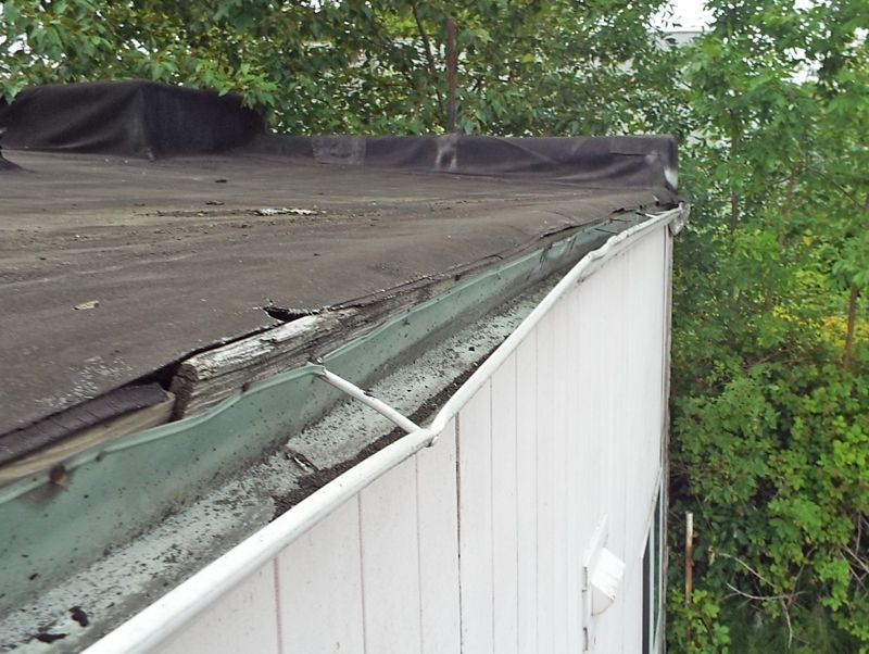
Reason:
Currently the IBC requires that low-slope built-up, modified bitumen, and single-ply
roof system metal edge securement be tested to resist wind and static loads, but
specifically excludes gutters that are used to secure these roof systems in many
cases. Studies of the aftermath of high-wind events revealed that many gutter
systems did not resist the loads that occur during these high-wind events. Examples
of these observations are shown below. SPRI developed the gutter test standard to
address this issue. The wind resistance tests included in this standard measure the
resistance of the gutter system to wind forces acting outwardly (away from the
building) and to wind forces acting upwardly tending to lift the gutter off of the
building. The standard also measures the resistance of the gutter system to static
forces of water, snow and ice acting downward. Following are examples of gutter
failures during high wind events observed during investigations conducted by the
Roofing Industry Committee on Weather Issues (RICOWI).
14 | P a g eGroup B 2019 Copyright © 2018 International Code Council, Inc.
15 | P a g eGroup B 2019 Copyright © 2018 International Code Council, Inc.
16 | P a g eGroup B 2019 Copyright © 2018 International Code Council, Inc.
17 | P a g eGroup B 2019 Copyright © 2018 International Code Council, Inc.
Cost Impact:
The code change proposal will not increase or decrease the cost of construction.
A cost comparison was done between a gutter system that would and would not
resist design wind loads. There was no difference in the cost of the two systems.
18 | P a g eGroup B 2019 Copyright © 2018 International Code Council, Inc.
IBC 15-6 – Chapter 15 reorganization
(Originally introduced in Group A – John Taecker and Bruce Johnson)
19 | P a g eGroup B 2019 Copyright © 2018 International Code Council, Inc.
IBC 23-2 – TWB issues
Chapter 23 Code WG Input: DRAFT – 22AUG17 – V1
[Includes notes taken during 2/16/18 Structural WG meeting.]
2302 Add reference to new mass (MT) timber definition in Section 202. Editorial
[2/16/18: Mass Timber definition: covered in Ch 2. Italicized definitions. No further
action.]
2303.1.4 Monitor changes to existing CLT product standard, PRG 320:
• Add requirement for sealant at CLT connections in 2303.1.4 or in Ch 7? Fire
WG?
• Consider option to create a requirement for heat delamination resistant (HDR)
adhesive for exposed CLT in Type IV B and C (similar to heat resistant adhesive (HRA)
in 2303.1.1.2)? Fire WG?
[2/16/18: Update to PRG-320 covered adhesives. Codes WG covered sealant. No
further action.]
2304.3.3 Shrinkage: update language to include mass timber platform framing
systems. Is there a height limit on platform framing? Structural WG?
[2/16/18: AWC to provide recommendation.]
2304.9.3 Update mechanically laminated decks to incorporate latest thinking on
NLT and/or DLT... Correlate with definitions. See S276-16 and S281-16 nailing required
for NLT and reference of 2304.9 to Heavy Timber in the 2018 IBC. Need to consider
20 | P a g eGroup B 2019 Copyright © 2018 International Code Council, Inc.
updating toenail to bearing requirement to allow prefab NLT and DLT panel erection?
Structural WG?
[2/16/18: Not a tall timber issue, but more likely a code proposal AWC would
submit to Group B process. Lucas Epp and Tanya Luthi available to discuss with
Brad Douglas to generate potential code proposal.]
2304.11 Establish equivalent thickness of SCL MT panel products for use as a
heavy timber panel product? (SCL minimum dimensions are already provided for
columns and beams in the 2015 IBC)? Fire WG?
[2/16/18: AWC to address in code if SCL panels become mainstream.]
2304.11 See G179-15 and G180-15 reorganization in 2018 IBC. Once changes are
published, need to update and correlate 2021 IBC proposed changes to be consistent
with new definitions of mass timber and heavy timber (heavy timber a subset of mass
timber with no change in substance). Also note G184-15 change in 2018 IBC to clarify
thickness of Type IV HT exterior walls. To be published by ICC… pending.
[2/16/18: Keep as action item. Correlations pending approval of Group A
proposals. AWC to assist Structural WG.]
2304.12.2.4 Update to include CLT? CLT is currently available in naturally durable
wood. Structural WG?
[2/16/18: Not a tall wood issue. Product standard, PRG 320, limits use of CLT to
dry service condition use. NDS does not permit CLT in exterior applications wet
service conditions either. Recommendation for BCAC to review the prohibition of
CLT panels in exterior conditions since the product standard PRG 320 might not
be prominent enough to provide direction to architects and building officials.]
2304.13 Update with research on composite concrete toppings on CLT or NLT?
Structural WG?
[2/16/18: Not a TWB issue, recommendation for BCAC. AWC says at this time
there is no plan to incorporate composite concrete toppings on CLT or NLT
panels into next revision of NDS.]
21 | P a g eGroup B 2019 Copyright © 2018 International Code Council, Inc.
2305 through 2307 Possible updates needed either here or in other parts of the
IBC to coordinate with AWC Special Design Provisions for Wind and Seismic for mass
timber diaphragms and/or for ASCE 7 LRFD fire design. There is currently a white
paper and testing on mass timber diaphragms and ongoing research. Structural WG?
[2/16/18: Not a TWB issue, recommendation for AWC to incorporate into NDS via
already formed task group when supporting research becomes available.]
22 | P a g eGroup B 2019 Copyright © 2018 International Code Council, Inc.
IBC 15-7 (S22-16) Roof Aggregate – NIST
23 | P a g eGroup B 2019 Copyright © 2018 International Code Council, Inc.
IBC 19-1 – Re-bar specifications
(Introduced at 9.11.2018 WG call)
Revise as follows:
1901.5 Construction documents. The construction documents for structural concrete construction shall include:
1. The specified compressive strength of concrete at the stated ages or stages of construction for which each
concrete element is designed.
2. The specified strength or grade of reinforcement.
3. The size and location of structural elements, reinforcement and anchors. See Table 1901.5 for reinforcement
bar sizes.
4. Provision for dimensional changes resulting from creep, shrinkage and temperature.
5. The magnitude and location of prestressing forces.
6. Anchorage length of reinforcement and location and length of lap splices.
7. Type and location of mechanical and welded splices of reinforcement.
8. Details and location of contraction or isolation joints specified for plain concrete.
9. Minimum concrete compressive strength at time of posttensioning.
10. Stressing sequence for posttensioning tendons.
11. For structures assigned to Seismic Design Category D, E or F, a statement if slab on grade is designed as a
structural diaphragm.
TABLE 1901.5 REINFORCEMENT BAR SIZES
NUMBER NOMINAL DIAMETER NOMINAL AREA NOMINAL WEIGHT
(inches) (square inches) (pounds/foot)
3 0.375 0.11 0.376
4 0.500 0.20 0.668
5 0.625 0.31 1.043
6 0.750 0.44 1.502
7 0.875 0.60 2.044
8 1.000 0.79 2.670
9 1.128 1.00 3.400
10 1.270 1.27 4.303
11 1.410 1.56 5.313
14 1.693 2.25 7.65
18 2.257 4.00 13.60
For SI: 1 inch = 25.4 mm; 1 square inch = 645.16 mm2; 1 pound/foot = 1.488 kg/m
Reason: This is an editorial change to bring useful information into the code. This
information can be used by all types of code users to understand and verify re-bar size
requirements consistent with industry sizing. The sizing information shown is consistent
with ACI 318 and ASTM A615.
24 | P a g eGroup B 2019 Copyright © 2018 International Code Council, Inc.
Cost Impact: This proposal will neither increase nor decrease the cost of construction
as it is editorial in nature.
25 | P a g eYou can also read