Guidelines Reliably Welding Plastic Single Ply Membranes - Roof Applications - Inter-Supply AS
←
→
Page content transcription
If your browser does not render page correctly, please read the page content below
Roof Applications

                                         Swiss
                                         made

                  Guidelines
                  Reliably Welding
                  Plastic Single Ply Membranes

www.leister.com                 We know how.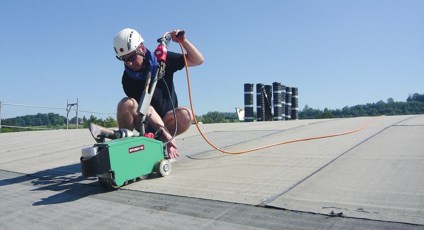
Content
1. Introduction............................................................................................................................ 3

2. Basic Principles of Welding Single Ply Membranes............................................................. 3

3. Prerequisite for Modern Automatic Welders......................................................................... 5

     3.1 Closed-loop Technology................................................................................................... 5
     3.2 Operating Automatic Welders........................................................................................... 6
     3.3 Greater Fastening Screw Load......................................................................................... 7

4. Differences Between the Most Common Single Ply Membranes........................................ 7

     4.1 TPO................................................................................................................................. 8
     4.2 PVC................................................................................................................................. 8
     4.3 Welding Window Service.................................................................................................. 8

5. Recommended Welding Parameters for Welding Machines................................................ 9

6. How to Create Simple and Reliable Plastic Seams ........................................................... 10

     6.1 Before Welding............................................................................................................... 10
     6.2 During the Welding Process........................................................................................... 12
     6.3 Implementing Details...................................................................................................... 15
     6.4 After Welding................................................................................................................. 16
     6.5 Evaluating the Seam...................................................................................................... 17
     6.6 Common Faults.............................................................................................................. 18

7. Greater Control with the MyLeister App.............................................................................. 20

8. IQDF...................................................................................................................................... 20

2                                                                                                                        www.leister.com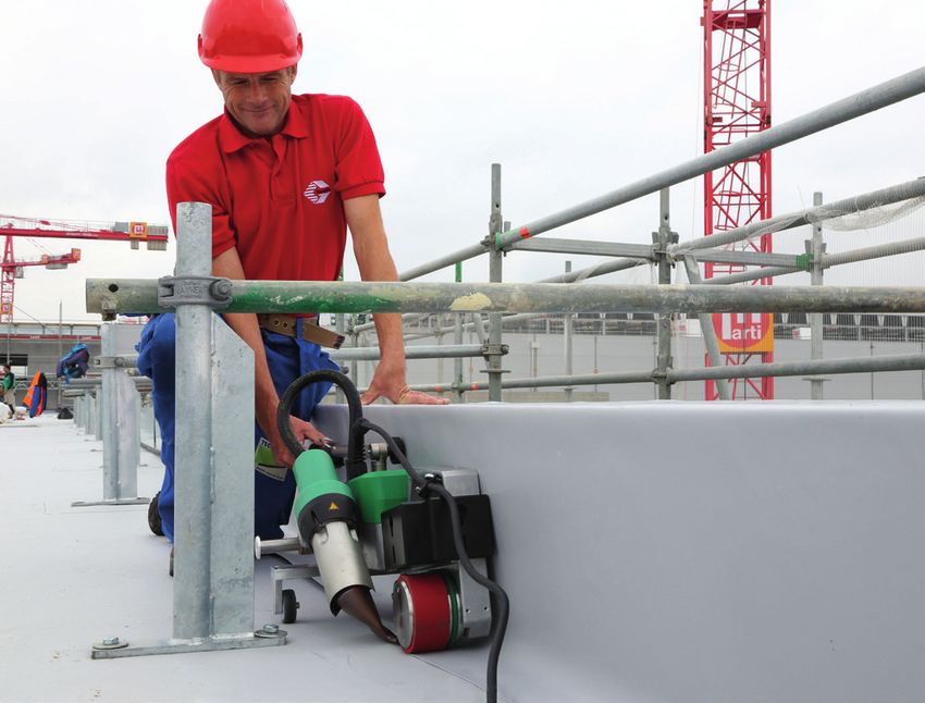
1. Introduction
When working on the roof, you always need to be able to fully rely on your devices. This is our firm belief. And this
is why you should certainly have high expectations of a Leister automatic roof welding machine: We guarantee to
provide you with maximum device reliability and the best all-round service.

Our welding machines are highly dependable, even when operated under difficult conditions , such as undervolta-
ge. A high level of flexibility is also required when it comes to automatic welders. Our machines are used in nume-
rous roof applications, as well as in situations where space is at a premium. With their sophisticated ergonomics,
the easy-to-handle automatic roof welding machines are keeping abreast of the trend, which is moving away from
manual welding and in the direction of automatic welding.

We always strive to tailor the machines to meet our customers' needs in the best way possible. Our development
department is continually carrying out research into new technologies so that we can offer you the highest-possible
quality. This is why you can count on Leister to provide machines that use state-of-the-art technology. The next
generation of automatic welders will offer greater process control utilizing the MyLeister app, where key welding
parameters are recorded so that possible deviations can be displayed with a report.

                                   Roland Beeler                                              Paul Röthlin
                                   Head of Business Line                                      Technical Sales
                                   Plastic Fabrication                                        Engineer
                                   Roofing & Flooring

2. Basic Principles of Welding Single Ply Membranes
In principle, it is easy to install and weld thermoplastic membranes. The formulation of today's single-ply membranes
allows for a favorable welding window. These guidelines should help you to join the sheets in a reliable and cost-ef-
fective manner. Increased seam integrity is just one of the guarantees with a latest-generation automatic welder
with closed-loop technology. The parameters are constantly monitored, making ergonomic and safe working
possible. Safety and weld quality are significantly higher with an automatic welder, as all welding parameters are
constantly checked and regulated:
    • • Temperature
    • • Speed
    • • Pressure
    • • Air volume

The welding is described with the following parameters in accordance with DVS 2225-4: temperature, speed,
pressure. In accordance with DVS 2225-4, do not weld at temperatures below 5°C as otherwise the membrane
will be stressed too much. To illustrate the interaction of the parameters, the following must be taken into account:

 Welding performance = Temperature x air volume (undervoltage must be taken into account)
									Speed

In other words, the speed must be adjusted as soon as changes are made to a parameter such as temperatu-
re / air volume. Otherwise, the welding parameters will no longer be in equilibrium and, under certain circum-
stances, it will no longer be possible to create a molecularly homogeneous seam. It is not possible to com-
pensate for excessive welding temperatures with the speed as the molecules could already be destroyed.

                                                                                                                   3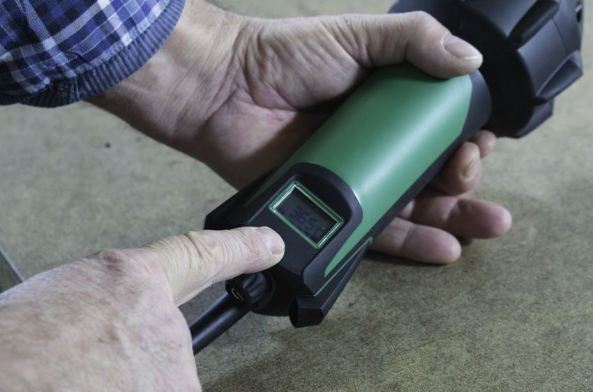
Example: If the air volume is reduced by 10%, then the speed should also be reduced by 10%. If the original speed
was 4 m/min, it must therefore be reduced to 3.6 m/min. With a Leister automatic welder with display function, the
parameters are maintained constantly using closed-loop technology (regulated technology). Thanks to the integra-
ted power reserve, the parameters are also guaranteed in the event of undervoltage of up to 20%.
    • The time and speed factor is very important! The hot air must have enough time to fuse the material;
      otherwise, it will not be possible to create a good seam. Generally, a distance of 25 mm is specified for
      manual hand welding, and 42 mm distance when using an automatic welder.
    • The master parameter when welding plastic and bitumen is the temperature, and should not be changed
      initially should parameter adjustments be required.
    • It is important to ensure that enough pressure is available during the welding process.
    • The contact pressure must be adapted depending on the material type / thickness and the substrate.

                                     Balance Homogeneous welding seam
           100
            90
            80
            70
            60
            50
            40
            30
            20
            10
             0
                                                     Welding performance

                                   Temperature              Air flow         Speed

                 Interaction between the welding parameters without taking pressure into account

    • The welding parameters can be determined with a 10-second test with a gap of +/- 5 mm while heat is
      applied (400–450 degrees). The materials can also be defined using a sample by fusing the materials.
    • It is important to ensure that the nozzle does not narrow.

      1

      2

          1 right
          2 wrong      Reason:
                       - Clogged or bent nozzle
                       - Insufficient air supply
                       - Defective heating element

4                                                                                             www.leister.com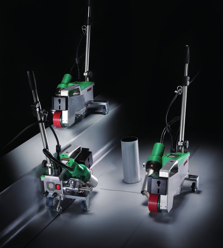
• The seam to be welded must be clean and dry.
   • If moisture has penetrated into the seam to be welded, it must be dried or the moist area must be cut out.
   • It is important to ensure that any seam between a waterproofing membrane which has become “aged” or
     "contaminated" in terms of weldability as a result of an installation delay (between surface and parapets /
     firewalls) and newly dried materials be prepared properly before welding in order to guarantee a homoge-
     neous joint.

3. Prerequisite for Modern Automatic Welders
3.1 Closed-loop Technology
We recommend using closed-loop technology, which keeps the parameters constant and offsets voltage fluctu-
ations on the construction site. The differences between the electronic systems and the advantages of regulated
technology are listed below:

Closed-loop (regulated)                                       Open-loop (controlled)
• The welding parameters are constantly monitored             • Manual setting is not monitored
• Voltage fluctuations are offset                             • Voltage is not balanced
• Cable lengths are taken into account                        • Cable lengths cause undervoltage

Display with closed-loop technology                           Potentiometer with open-loop technology

In the event of undervoltage of more than 20%, state-of-the-art Leister automatic welders, such as the
VARIMAT V2 / UNIROOF AT, stop the welding process to guarantee a reliable seam.

                                                                                                                   5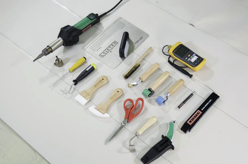
3.2 Operating Automatic Welders
The guide bar must not be held too high as otherwise this will affect the contact pressure.

Modern automatic welders have an adjustable transport axle allowing for close-edge welding, eliminating the need
for manual welding:

                                                        It's ergonomic, reliable, and safe!

                                                        Go to the video

It is now possible to weld close to the edge behind scaffolding poles thanks to the compact design.

                                                           Various major applications covered with just
                                                           one machine – the UNIROOF AT:

                                                          •   Basic overlap welding
                                                          •   Flashing details as close as 10 cm from parapets
                                                          •   On top of narrow parapet walls

6                                                                                              www.leister.com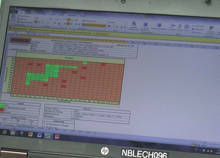
3.3 Greater Fastening Screw Load

Welding with automatic welder                                       Manual welding

As a result of the constant welding parameters with an automatic welder, the rated load of a fastener is considerably
higher than if the seam was created manually.

4. Differences Between the Most Common Single Ply Membranes
Today's commercial roofing manufacturers offer a wide variety of high-quality single-ply membranes. The most
commonly used materials are:
   • PVC (polyvinyl chloride)
   • TPO/FPO (thermoplastic polyolefin / flexible polyolefin)

Please note that single ply membranes have different polymers and formulations, therefore, care must be taken to
select the correct welding parameters. The typical welding parameters are shown below:

      Welder set temperature (°C)

                                            Welding speed (m/min)

           Typical welding windows for TPO and PVC

The differences between each product's welding parameters can be significant and must be taken into account
prior to welding.

                                                                                                                   7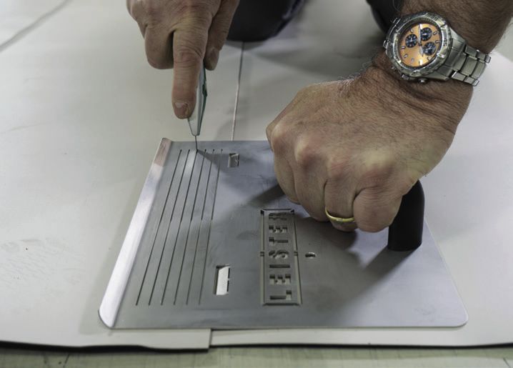
4.1 TPO
    • Ensure that the welding temperatures are not set too high, as excessive temperatures destroy the molecu-
      les. This cannot be offset by increasing the speed as the molecules will already have been destroyed by the
      excessive temperature.
    • In the event of high outdoor temperatures, we recommend lowering the welding temperature and not incre-
      asing the speed. The parameters can therefore deviate from those specified by the material manufacturer
      (with closed-loop [regulated] machines, the temperature correction is lower than with unregulated machi-
      nes).
    • When PE and PP are used as the raw materials for the FPO / TPO membranes, these change in length
      much more than PVC, which can lead to wave formation when heat is applied.
    • With the right welding parameters, FPO and TPO sheets have very favorable welding characteristics. For
      renovations or repairs, you can typically use the standard welding parameters, as the material absorbs less
      moisture than PVC. TPO sheets often have a longer life expectancy (no plasticizers).

4.2 PVC
    • The material can be more tolerant to temperature due to the plasticizers and different formulations.
    • If too much smoke develops during the welding process, the muriatic acids will escape. Do not breathe in
      the fumes!

4.3 Welding Window Service
Leister offers a service to create a welding window for material manufacturer partners. The ideal parameters are
determined using standardized procedures and brand new material.

As a general rule, all welding must be carried out using clean and dry material. Welding dirty material is prohibited.
It must be cleaned first.

8                                                                                                 www.leister.com
5. Recommended Welding Parameters for Welding Machines
Machine selection overview
Roof automatic welders
VARIMAT S
VARIMAT V2
UNIROOF AT VARIMAT V2 TRIAC Drive ST BITUMAT B2
PVC: 2.0 m/min, 520°C, PVC: 4.0 m/min, 550°C, PVC: Level 1.5 Nozzle up to 100 mm
air volume 100 % air volume 85 % (1 m/min, 400°C, air
TPO: 2.5 m/min, 450°C, TPO: 5.0 m/min, 500°C, volume 100 %) Modified bitumen:
100 % air volume 100 % TPO: Level 2.5 5.0 m/min, 650°C,
Recommended initial welding parameter
(1.5 m/min, 380°C, air air volume 100 %
depending on membrane type
UNIROOF ST VARIMAT S: volume 100 %)
(tested at 20°C room temperature):
PVC: 1.8 m/min, 520°C, PVC: Temperature level
100 % 8.5–9 (550°C)
TPO: 2.0 m/min, 450°C, TPO: No trailing roller,
100 % so can only be used to a
limited degree
Machine selection overview
Hot-air hand tools
HOT JET S
TRIAC ST TRIAC AT ELECTRON ST
PVC: from 360°C
Initial welding parameters for PVC: from 360°C PVC: from 360°C Modified bitumen:
TPO: from 295°C
manual welding TPO: from 295°C TPO: from 295°C From 550°C
With 20 mm nozzle
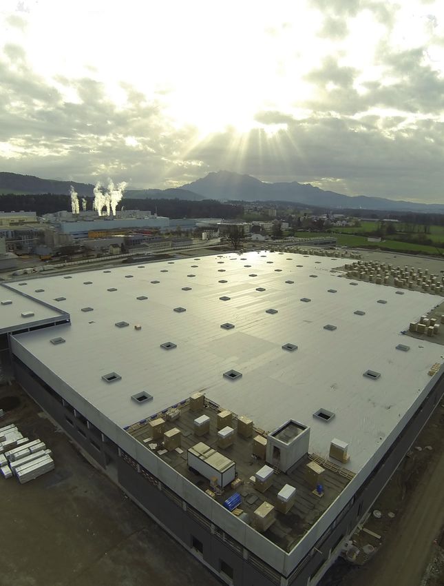
Welding modified bitumen with hot air, thus eliminating open flame.
9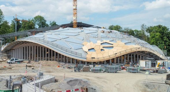
6. How to Create Simple and Reliable Plastic Seams
6.1 Before Welding
Everything is easier with the right accessories.
Accessories are part of a reliable and cost-effective
welding process.

Check that the machines are working and check for
voltage.

Clean the filters and heating elements periodically for the
best performance:

• The heating elements do not get clogged and the
  correct temperatures are therefore ensured

• High air volume thanks to clean filters

10                                                            www.leister.com
Check the nozzle:
Clean if there are slag deposits on the nozzle.
Check that the nozzle is the correct shape for maximum
performance:
Damaged nozzles cause leaks or incorrect welding.
√
Check the nozzle is set correctly on the automatic welder:
More info in the machine operation manual.
The nozzle can be set correctly with the setting gage.
A
A = 42 mm +/-2
B
B = 1–2 mm
C = 1 mm
C
Perform a test weld manually and with the welding
machine.
Caution: Always factor in the material manufacturer's
specifications and installation instructions. Set the welding
parameters each day, taking changes in the weather into √
account. Test welds must be carried out in the morning
and after midday.
The weld is correct if a straight, clean tear can be achie-
ved when you peel lengthwise.
11Consider inserting a sheet metal starting plate at the start
and end of a machine-welded seam.
This increases the quality of the transitions between ma-
nual and machine-welded seams.
6.2 During the Welding Process
The electrical connection and cable routing on the roof
must be planned carefully in order to avoid interference..
√ Cable laid correctly
Cable above nozzle
Cable in welding
process
12 www.leister.comGuiding machines:
Do not tilt the welding machine sideways during the
welding process, otherwise the contact pressure will no
longer be consistent across the welded seam.
√
Adjust the contact pressure to the membrane thickness
and supplement with additional weights:
• Membranes with a thickness of 2 mm or greater should
be supplemented with additional weights.
• TPO sheets require more contact pressure than PVC
sheets. The contact pressure must also be adjusted
to the sheet thickness. Soft and hard substrates (e.g.,
thermal insulation) can also affect the contact pressure.
Softer substrates require more contact pressure.
Using 400 V automatic welders is advantageous.
With 400 V, voltage fluctuations are better offset and
more power is available.
At 2.5 mm², the cable lengths should not be much more
than 50 m to ensure that no undervoltage can occur.
13Important Facts
• The cable should be copper, with as large a cross-section as possible
• The cable should be as short as possible
• The following rules of thumb apply:
Automatic welding machines: maximum 50 m with 2.5 mm² cable, e.g., VARIMAT V2 4.6 kW 230 V /
over 50 m 4.0 mm² Manual welding: maximum 50 m with 1.5 mm² cable, e.g., TRIAC AT/ST 1.6 kW 230 V
• Plug for 20 A and a secure connection
• A generator should provide at least10 kW
• A stable electrical environment is required
• The fuse should have 20 A for 230 V and 16 A for 400 V
Varimat V2 230 V / 4600 W Varimat V2 400 V / 5700 W
Copper
1.0 mm2 1.5 mm2 2.5 mm2 1.0 mm2 1.5 mm2 2.5 mm2
cable
50 m 200 V (-13%) 209 V (-9%) 217 V (-6%) 377 V (-6%) 384 V (-4%) 390 V (-2.5%)
100 m 177 V (-23%) 192 V (-17%) 205 V (-11%) 256 V (-11%) 370 V (-8%) 381 V (-5%)
150 m 159 V (-31%) 177 V (-23%) 194 V (-16%) 338 V (-16%) 356 V (-11%) 372 V (-7%)
200 m 144 V (-37%) 164 V (-28%) 184 V (-20%) 321 V (-20%) 344 V (-14%) 363 V (-9%)
250 m 132 V (-43%) 154 V (-33%) 176 V (-24%) 306 V (-23%) 332 V (-17%) 355 V (-11%)
300 m 121 V (-47%) 144 V (-37%) 168 V (-27%) 292 (-27%) 321 V (-20%) 347 V (-13%)
350 m 112 V (-51%) 136 V (-41%) 160 V (-30%) 280 (-30%) 311 V (-22%) 340 V (-15%)
400 m 105 V (-54%) 128 V (-44%) 154 V (-33%) 268 (-33%) 301 V (-25%) 332 V (-17%)
450 m 98 V (-57%) 121 V (-47%) 148 V (-36%) 258 (-36%) 292 V (-27%) 326 V (-19%)
500 m 92 V (-60%) 115 V (-50%) 142 V (-38%) 248 (-38%) 284 V (-29%) 319 V (-20%)
550 m 87 V (-62%) 110 V (-52%) 137 V (-41%) 239 (-40%) 276 V (-31%) 312 V (-22%)
Voltage drop due to cable length
When welding PVC, here are good seam indicators:
Even sheen, welding track clearly visible, slight bleed
√
√
14 www.leister.comWhen welding TPO, here are good seam indicators:
Even sheen, small track visible, no bleed out
√
√
6.3 Implementing Details
The transition between machine weld start/stops and
manual welds must be carefully performed to eliminate
any seam voids.
When performing flashing details, the material manu-
facturers' installation instructions must be observed.
15The T-joint must be handled in such a way that the entire
width of the weld is tightly welded. The material manu-
facturers' installation instructions must be observed.
With single-ply membranes, damage and leaks can be
repaired easily.
• Do not make the patch too small, minimum 8–10 cm.
• Be certain that welding surfaces are clean and dry.
√
6.4 After Welding
Keep the machines clean. Clean the gliding surfaces
periodically, lubricate them, and carry out any main-
tenance required.
• WD-40 is a cleaning agent and only has gliding pro-
perties in the short term.
16 www.leister.com6.5 Evaluating the Seam
EXAMO weld seam strength tests
• Mark and cut 50 mm strips
• Tensile tests according to EN 12317-2 – weld seam
strength: tear outside the weld
• Peel tests according to UEAtc recommendation for
reliable weld seam strength Ø ≥ 150 N / 50 mm,
min. ≥ 80 N / 50 mm
Check / acceptance report
• All weld seams must be checked mechanically with a
weld seam probe
• T-joints can be checked with a vacuum bell jar
• Once the work is complete, we recommend an
acceptance report
176.6 Common Faults In the event of high outdoor temperatures, e.g., in the summer, the welding temperatures must be reduced. The material to be welded will then need a lower temperature. If this is ignored, wrinkles may develop and, in the worst-case scenario, the molecules may be destroyed, which could lead to a leaky seam. Typical weld with wave formation and wrinkles at excessive welding temperatures From these images, it is evident that: a) The selected welding temperature was too high (even with high outdoor temperatures) The gloss is much too high and the impression of the air dam belt is apparent b) The material was not stretched c) The membrane was fastened before the welding process d) Welding over the fasteners is not permitted Typical wave and wrinkle formation at excessive welding temperatures. The welding temperature must be reduced to prevent wave formation! 18 www.leister.com
Wave formation must be avoided when laying the sheets
 as this can lead to leaks.

                                                                                     1

                                                                                     2

                                                                                     3
 Do not weld too hot:

 • Oil will escape and too many bubbles will develop

 An excessive number of patches must be avoided!

Membranes can be damaged by dirt or incorrect cleaning agents in such a way that welding is no longer possible
under certain circumstances.

As a result of different high outdoor temperatures, wave formation cannot be avoided in some circumstances.

                                                                                                              19
7. Greater Control with the MyLeister App
• Automatic data report of the welding parameters with the LQS roofing app
MyLeister app
• Access recommended welding parameters, as specified by the material manufacturer
• Greater control for the foreman and surveyor / assessor, allowing for improved quality control inspections
8. IQDF
If you need more information, there are also guidelines on quality assurance for flat roofs with plastic
geomembranes
www.iqdf.de
Elephant park at Zürich zoo, reliably sealed with a thermoplastic membrane.
20 www.leister.comYou can also read