Helmert Variance Component Estimation for Multi- GNSS Relative Positioning - gAGE/UPC
←
→
Page content transcription
If your browser does not render page correctly, please read the page content below
Article

Helmert Variance Component Estimation for Multi-
GNSS Relative Positioning
Mowen Li 1, Wenfeng Nie 1,2,3, Tianhe Xu 1,*, Adria Rovira-Garcia 4,*, Zhenlong Fang 1 and
Guochang Xu 1,5
 1 Institute of Space Sciences, Shandong University, 180 Wenhuaxi Road, Weihai 264209, China;
   mowenli@mail.sdu.edu.cn (M.L.); wenfengnie@sdu.edu.cn (W.N.); zhlfang@foxmail.com (Z.F.);
   xuguochang@hit.edu.cn (G.X.)
 2 Shandong Provincial Key Laboratory of Optical Astronomy and Solar-Terrestrial Environment,

   Shandong University, Weihai 264209, China
 3 State Key Laboratory of Geo-Information Engineering, Xi’an Research Institute of Surveying and Mapping,

   Xi’an 710054, China
 4 Research group of Astronomy and Geomatics (gAGE), Universitat Politecnica de Catalunya (UPC),

   08034 Barcelona, Spain
 5 Institute of Space Science and Applied Technology, Harbin Institute of Technology,

   Shenzhen 518000, China
 * Correspondence: thxu@sdu.edu.cn (T.X.); adria.roira@upc.edu (A.R.-G.); Tel.: +86-0631-562-2731 (T.X.);
   +34-93-401-25-31 (A.R.-G.)

 Received: 2 December 2019; Accepted: 21 January 2020; Published: 25 January 2020

 Abstract: The Multi-constellation Global Navigation Satellite System (Multi-GNSS) has become the
 standard implementation of high accuracy positioning and navigation applications. It is well known
 that the noise of code and phase measurements depend on GNSS constellation. Then, Helmert
 variance component estimation (HVCE) is usually used to adjust the contributions of different
 GNSS constellations by determining their individual variances of unit weight. However, HVCE
 requires a heavy computation load. In this study, the HVCE posterior weighting was employed to
 carry out a kinematic relative Multi-GNSS positioning experiment with six short-baselines from day
 of year (DoY) 171 to 200 in 2019. As a result, the HVCE posterior weighting strategy improved Multi-
 GNSS positioning accuracy by 20.5%, 15.7% and 13.2% in east-north-up (ENU) components,
 compared to an elevation-dependent (ED) priori weighting strategy. We observed that the weight
 proportion of both code and phase observations for each GNSS constellation were consistent during
 the entire 30 days, which indicates that the weight proportions of both code and phase observations
 are stable over a long period of time. It was also found that the quality of a phase observation is
 almost equivalent in each baseline and GNSS constellation, whereas that of a code observation is
 different. In order to reduce the time consumption of the HVCE method without sacrificing
 positioning accuracy, the stable variances of unit weights of both phase and code observations
 obtained over 30 days were averaged and then frozen as a priori information in the positioning
 experiment. The result demonstrated similar ENU improvements of 20.0%, 14.1% and 11.1% with
 respect to the ED method but saving 88% of the computation time of the HCVE strategy. Our study
 concludes with the observations that the frozen variances of unit weight (FVUW) could be applied
 to the positioning experiment for the next 30 days, that is, from DoY 201 to 230 in 2019, improving
 the positioning ENU accuracy of the ED method by 18.1%, 13.2% and 10.6%, indicating the
 effectiveness of the FVUW.

 Keywords: Multi-GNSS; Helmert variance component estimation (HVCE); weighting strategy;
 relative positioning

Sensors 2020, 20, 669; doi:10.3390/s20030669                                   www.mdpi.com/journal/sensors
Sensors 2020, 20, 669                                                                          2 of 18

1. Introduction
     Since the United Stated Global Positioning System (GPS) became fully operational in 1995
(https://www.gps.gov), the Global Navigation Satellite System (GNSS) continuously developed
toward a Multi-constellation GNSS (Multi-GNSS) paradigm [1]. The Russian GLObal NAvigation
Satellite System (GLONASS) is adopting a code division multiple access (CDMA) signal, substituting
the original frequency division multiple access (FDMA) (https://www.glonass-iac.ru/). The European
Galileo plans to complete Galileo constellation with 30                         satellites by 2020
(http://www.esa.int/Applications/Navigation/Galileo/What_is_Galileo). For the BeiDou Navigation
Satellite System (BDS) of China, BDS-2 and BDS-3 satellites are currently used together
(http://www.beidou.gov.cn/), and BDS-3 will be completed by 2020 for a global service [2].
     By providing more satellites and signals, Multi-GNSS can benefit the GNSS community in many
aspects. It can not only improve the positioning accuracy for both precise point positioning (PPP) and
real-time kinematics (RTK), but also shorten convergence time to obtain the final positioning accuracy
more quickly [3–6]. In the Multi-GNSS context, the International GNSS Service (IGS) initialized the
Multi-GNSS EXperiment (MGEX) in 2014 [7], aiming to provide Multi-GNSS products such as precise
orbit, clock and satellite bias. Since then, MGEX products have enabled Multi-GNSS applications,
such as global ionosphere modelling [8], water vapor determination [9], precise agriculture [10],
crustal deformation [11] and GNSS-Reflectometry-based altimetry [12].
     It is well known that the quality of the measurements from different GNSS constellations is not
homogenous. Among other reasons, the discrepancies can be attributed to the following: the satellite
orbits are different not only between GNSSs but also within the same constellation. For instance, BDS
contains three types of orbit satellites, medium Earth orbit (MEO), geostationary Earth orbit (GEO)
and inclined geo-synchronous orbit (IGSO) [13,14]; the signal structure adopted by GPS, BDS and
Galileo is CDMA, while that by GLONASS is FDMA.
     Therefore, many weighting methods are proposed in the literature to determine the weight of
GNSS according to the quality of observations: the carrier-to-noise ratio [15], elevation-dependent
(ED) weighting method [16], azimuth-dependent-elevation weighting model [17] and the method
based on signal-in-space ranging errors (SISRE) information [18], among others. Variance component
estimation (VCE) can also be used to adjust the contribution of different GNSS constellations by
determining their individual variances of unit weight [19]. The theoretical algorithm of the Helmert
variance component estimation (HVCE) was deeply studied [20–22] and a simplified version of the
rigorous HVCE was proposed [23].
     From then on, HVCE was applied to many different geodetic areas [24–27]. For positioning
applications, the algorithm of HVCE was simplified in Kalman filtering to save computation load
and to achieve good convergence time in GPS single point positioning (SPP) [23]. Robust HVCE can
provide suitable weights for various observation groups and guarantee the reliability of the
positioning results in network adjustment [28]. As for Multi-GNSS applications, HVCE was proven
to perform well in Multi-GNSS time and frequency transfer [29], the Inertial Navigation System (INS)
tightly coupled integrated with Multi-GNSS PPP [30] and Multi-GNSS positioning. HVCE can
determine the weight matrix of GPS/BDS observations, reaching horizontal accuracy of 0.2 m in
pseudorange differential positioning [31]. The modified VCE and HVCE were combined in GPS/BDS
PPP, which significantly improved the positioning accuracy and reduced the convergence time [32].
Finally, HVCE applied in GPS/BDS/GLONASS pseudorange-based relative positioning improved
positioning accuracy by 11.5% [33].
     However, these aforementioned works paid more attention to the improvement in positioning
accuracy obtained by HVCE posterior weighting method, rather than to the time-varying features of
the variances of unit weight and their further applications. Therefore, our present study focuses on
the long-term time-varying characteristic of HVCE weights proportion of Multi-GNSS, by analyzing
variances of unit weights of both phase and code observations. Based on the one-month stability of
HVCE weight proportions, variances of unit weight were applied as prior information for the test of
the next month, which was found to be efficient at enhancing positioning accuracy and time-saving
in the Multi-GNSS process.
Sensors 2020, 20, 669 3 of 18
The paper is organized as follows. We first present the theory of HVCE robust Kalman filtering
and its algorithm implementation in Section 2. Then, Section 3 introduces the experimental setups
and station status during the experimental data campaign. The results of accuracy improvements
achieved by HVCE posterior weighting-based Multi-GNSS positioning are presented in Section 4.
Finally, we discuss experimental results associating with previous works and summarize all
significant conclusions in Section 5.
2. Method
2.1. Helmert Variance Component Estimation for Robust Kalman Filtering
Different types of orbit, signal structure, data quality and measurement type, require different
GNSS observations to be properly weighted. The HVCE-based robust Kalman filtering can balance
the contributions of different grouped data and provide individual variances of unit weights. In what
follows, we provide the rigorous deduction of HVCE-based robust Kalman filtering for Multi-GNSS
positioning.
The classic Kalman filtering solution Equations can be expressed as
X̂ = X + K(L − AX) (1)
Q̂X = (I − KA)QX (2)
K = QX AT (AQX AT + QV )−1 , (3)
where X and QX are the predicted state parameters and its covariance matrix; X̂ and Q̂X are
their estimated values, respectively; L and QV are an observation vector and its covariance matrix;
A is coefficient matrix of predicted state parameters; K is called gain matrix; and I denotes the
unit matrix. One popular prior weighting strategy used in classic Kalman filtering to calculate
observation covariance matrix is the ED weighting method:
QVi = kratio sin−2 θi ⋅ε2 phase (4)
where the Q vi and θi are the variance and the satellite elevation angle of the i th observation;
ε2 phase is the given variance of phase observation with ε phase set as 3 mm in this paper; and k ratio
denotes a noise-ratio of k ratio = 1 for phase observations, while kratio = 100 for code observations.
2
However, the classic Kalman filtering is easily affected by the outlier in observations, and in our
study, the observations are dependent after being double-differenced to implement relative
positioning. Therefore, the weight matrix of L has to be modified as [34]:
(PV )ij = γ ii γ jj (PV )ij (5)
1
Ri (QV )ii ≤ c
γ ii = c (6)
R (QV )ii Ri (QV )ii > c
i
PV = Qv−1 (7)
where subscript i and j are the i th row and j th column of a specified matrix; γ ii and γjj are
two reduction factors; R i is the residual of the Li ; c denotes a constant threshold that is usually
chosen as 1.3–2.0.
This yields a robust Kalman filtering with the updated observation covariance matrix Qv :
K = QX AT (AQX AT + QV )−1 (8)
QV = PV−1 . (9)Sensors 2020, 20, 669 4 of 18
Let us assume that there are m groups of data according to code and phase observations of
different GNSSs at a given epoch. Associating Equations (2) and (3) with HVCE theory [19–22], the
solution of variance of unit weight of each individual observation group can be expressed as
−1
σ12 s1,1 s1,2 s1,m R 1T Q V1
−1
R1
2 T −1
σ 2 = s 2 ,1 s 2,2 s 2 ,m R 2 QV 2 R 2 (10)
2 T −1
σ m s m ,1 s m ,2 s m ,m R m Q Vm R m
si ,i = n i − 2tr(Ni N−1 ) + tr(Ni N−1 Ni N−1 )
si ,j = s j,i = tr(Ni N−1 N j N−1 )
, (11)
Ni = ATi Q−Vi1 Ai
N−1 = Q ˆ
X
where σi is the estimated variance of unit weight and ' tr ' stands for trace of a matrix. R i , Ni
2
and ni stand for the residual vector, normal matrix and observation number of the ith group,
respectively. According to the variance of unit weight solution calculated from Equations (10) and
(11), one can conveniently update the covariance matrix of the i th observations group using:
= σ i Q , i = 1, 2, , m
2
Q (12)
Vi
c 0 Vi
)−1 ,
K = QX AT (AQX AT + Q (13)
V
represents the updated covariance matrix of the i th observations group.
where Q Vi
It should be noted that c0 is an arbitrary constant, which is usually one of the estimated
variances of a unit weight. Considering the GNSS consistency, we chose σG,L of GPS phase
2
observations group as the substitute for c0 . Once the observation covariance matrix is updated,
Equation (3) can be replaced by Equation (13) and used to calculate new state parameters.
2.2. Flow Chart of Multi-GNSS HVCE for Robust Kalman Filtering Algorithm
In the present paper, an iterative algorithm is presented to calculate the final solution of variance
of unit weight σ2 and state parameters. The flow chart of the algorithm is presented in Figure 1. At
the start of the loop, Equations (1)–(9) are used to calculate an initial X̂ and residual vector R of
robust Kalman filtering. Then, the variance of unit weight σ2 of phase and code observations of
GNSSs are calculated using HVCE algorithm expressed by Equations (10) and (11). At the end of the
iteration, each observation group’s covariance matrix Q Vi is updated using Equation (12) and
for the robust Kalman filtering of next iteration.
combined to a new covariance matrix QV
Robust Final Robust
Observation HVCE Update Satisfy
Kalman Kalman
Equation Algorithm Covariance Criterion?
Filtering Filtering
Yes
No
Figure 1. Flow chart of Multi-GNSS HVCE for robust Kalman filtering.
The end of the loop depends on the availability of variance of unit weight σ2 of each
observation group. According to HVCE theory, the final solution should satisfy the criterion that all
variances of unit weight σ2 of different observation groups are numerically equal. However, in the
real implementation of the iterative algorithm, the obtainable result is a cluster of approximatelySensors 2020, 20, 669 5 of 18
equal variances of unit weight σi . Assuming that the criterion of final solution is satisfied after
2
several iterations, it is deduced the equivalent critical Equation for all observation groups as
σi2,z
− 1 ≤ δ , c 0 ,z = σG2 ,L , (14)
c 0 ,z
where z is the number of the iterations. δ denotes the threshold value of criterion, which is a
diminutive value close to zero ( δ = 0.01 is used in our experimentation). Therefore, the final solution
of variance of unit weight of the i th observation group with respect to the original covariance
matrix can be expressed as
z σi,j
2
σi2 = ∏ , (15)
j=1 c0,j
where the final variances of unit weight σi2 of phase and code are employed as the representations
of weight proportion for the further analysis in our study.
Before the experiment, we set the algorithm to iterate 7 times ( z = 7 ) to calculate final solution
for variances of unit weights of observation groups. As a result, the variances of unit weight reached
97.2%, 99.5% and 99.9% of the final solution after the first, second and third iteration on average,
which means that most of loops will stop after the second iteration, as the δ is set as 0.01.
3. Experiment Setup
3.1. Station Selection
For the purpose of evaluating the availability of HVCE posterior weighting strategy in robust
Kalman filtering and analyzing the weight proportions of GPS, BDS, GLONASS and Galileo in
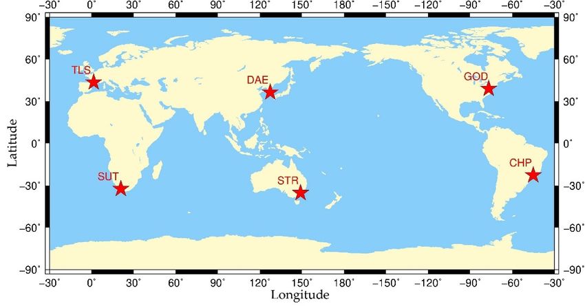
different areas, we selected twelve IGS stations located in five different continents to form six
independent, short baselines shown in Figure 2. The basic information of all stations and baseline
distributions for relative positioning is shown in Table 1.
Table 1. Station information and baseline distribution.
Baseline Length(m) Station Receiver Type Antenna Type
CHPG TRIMBLE NETR9 TRM59800.00 NONE
CHP 1850
CHPI SEPT POLARX5 TPSCR.G3 NONE
DAEJ TRIMBLE NETR9 TRM59800.00 SCIS
DAE 0
DAE2 TRIMBLE NETR9 TRM59800.00 SCIS
GODE SEPT POLARX5TR AOAD/M_T JPLA
GOD 65
GODN JAVAD TRE_3 DELTA TPSCR.G3 SCIS
STR1 SEPT POLARX5 ASH701945C_M NONE
STR 70
STR2 TRIMBLE NETR9 LEIAR25.R3 NONE
SUTH SEPT POLARX5 ASH701945G_M NONE
SUT 142
SUTM JAVAD TRE_3 JAVRINGANT_G5T NONE
TLSE TRIMBLE NETR9 TRM59800.00 NONE
TLS 1265
TLSG SEPT POLARX5TR TRM59800.00 NONE
Relative positioning with short baselines was selected as the experimental strategy because it
eliminates satellite and receiver-dependent errors (e.g., clock error and hardware delays) and most
parts of signal propagation-dependent errors (e.g., ionosphere and troposphere delays)
[35].Therefore, the unknown parameters estimated in the HVCE-based robust Kalman filtering are
the coordinates of rover station, the ambiguities and the inter-frequency bias (IFB) of GLONASS
observations when the baseline receivers are of different types.Sensors 2020, 20, 669 6 of 18
Figure 2. Locations of six independent baselines with co-located International GNSS Service (IGS)
stations.
3.2. Data Processing Strategy
Our daily kinematic relative positioning uses: single-frequency pseudo-range and carrier phase
observations, i.e., GPS L1, BDS B1, GLONASS L1 and Galileo E1, MGEX broadcast ephemeris, and
both BDS-2 and BDS-3 satellites, including MEO, GEO and IGSO. The reason that only single-
frequency observations are used is to avoid the influence of the second frequency observations in the
determination of variance of unit weight for each constellation. The campaign dated from 2019 and
it is divided into two parts of one month each, from day of year (DoY) 171 to 200 and from DoY 201
to 230, detailed in what follows. The initial noise levels of the pseudorange and carrier-phase of all
GNSS constellations are set as 0.3 m and 0.003 m, respectively. Besides, a white noise of 30 m is
applied to each component of the coordinate parameters in the Kalman filtering. Considering the
computational efficiency, the data sampling interval is set to 180 s. The positioning experiments are
computed by a Red Hat Enterprise Linux Server with the 1.60 GHz CPU.
For the purpose of evaluating the weight proportion of Multi-GNSS in different baselines, five
strategies are proposed to carry out the kinematic relative positioning experiment: ED prior
weighting-based GPS-only and Multi-GNSS (G + C + R + E) strategy (ED GPS-only and ED Multi-
GNSS for short), and their corresponding HVCE posterior weighting-based strategies (HVCE GPS-
only and HVCE Multi-GNSS for short). Finally, in order to obtain the high accuracy result and reduce
the time consumption of the HVCE method at the same time, the variances of unit weight over the
30 days are averaged and then frozen as a priori information in the positioning experiment, named
frozen variances of unit weight (FVUW). The Multi-GNSS FVUW strategy is extended to the
positioning experiment for 30 days from DoY 201 to 230.
Note that the observations from 00:00:00 DoY 192 to 12:15:46 DoY 193 for station GODN and
observations of DoY 171 for station TLSG in Receiver INdependent EXchange (RINEX) format are
missing in the IGS archive (ftp://cddis.gsfc.nasa.gov/pub/gps/data/daily/). The final coordinate
solution of DoY 185 provided by IGS is used as the reference to calculate root mean square (RMS),
and the station coordinate (x, y, z) components in the WGS84 reference frame are transformed into
ENU components. The RMS values are computed from the epoch when the 3D positioning error is
continually lower than 0.1 m. Particularly, the averaged convergence time and number of available
positions whose 3D positioning errors are below 0.1 m are shown in Table 2.Sensors 2020, 20, 669 7 of 18
Table 2. Averaged convergence time and number of available positions per day for five strategies.
ED GPS-Only HVCE GPS-Only ED Multi-GNSS HVCE Multi-GNSS FVUW Multi-GNSS
Convergence Time (minutes)
18.4 16.6 6.1 5.1 5.2
Number of Available Positions Per Day
459.8 462.1 475.8 477.1 476.8
Before assessing the experimental results, the average number of common satellites and
positioning dilution of precision (PDOP) values of individual and combined GNSSs in each baseline
during the experiment are presented in Table 3.
Table 3. Average common satellite number and positioning dilution of precision (PDOP) values of
different baselines.
Baseline G C R E G+C+R+E
Average Available Satellites Number
CHP 7.87 4.18 5.66 5.86 22.92
DAE 7.73 11.42 5.82 4.42 29.31
GOD 7.56 5.26 6.04 5.23 24.01
STR 7.76 10.95 5.92 5.27 29.87
SUT 7.67 7.74 5.69 5.79 26.85
TLS 7.66 5.13 6.13 5.68 24.51
Average PDOP Value
CHP 1.17 2.85 1.62 1.58 0.67
DAE 1.21 1.08 1.52 2.47 0.60
GOD 1.25 2.04 1.49 1.82 0.66
STR 1.21 1.11 1.48 1.78 0.59
SUT 1.22 1.25 1.62 1.62 0.62
TLS 1.25 2.49 1.45 1.64 0.66
It can be read that Multi-GNSS (G + C + R + E) provides the larger number of available satellites
for all baselines. As a result, the PDOP values of Multi-GNSS are smaller than single-GNSS. Focusing
on the performance of different GNSSs, GPS and GLONASS provide more consistent positioning
conditions, with average numbers of 7.7 and 5.9 satellites and corresponding PDOP values of 1.2 and
1.5 for all baselines. For Galileo, the average number of available satellites is stable at approximately
5.5 with the PDOP value of 1.7 in the most of baselines except DAE in Asia. In the case of BDS, as the
BDS-3 constellation is under construction and BDS-2 constellation has been completed, the
performance of BDS is much better than any other systems in Asia-Pacific (DAE, STR), with more
than 10 available satellites, and its PDOP value approaches to 1. In this regard, BDS can provide
equally good satellite geometry as GPS and GLONASS do in South Africa (SUT). However, BDS has
a limited advantage in America (CHP, GOD) and Europe (TLS) with less than six available satellites.
4. Experimental Results and Discussion
In the present section, both phase and code observation weight proportions of all Multi-GNSS
baselines are discussed separately at first. Afterwards, the positioning performance of HVCE
posterior weighting method is evaluated for all baselines. Finally, based on the stability of the weight
proportion of both phase and code observations, the effectiveness of FVUW Multi-GNSS strategy in
positioning is assessed.Sensors 2020, 20, 669 8 of 18
4.1. Weight Proportions of Multi-GNSS Phase and Code Observations
As mentioned in Section 2, the variance of unit weight generated from the HVCE posterior
weighting strategy is a criterion to evaluate the quality of different observation types from various
GNSSs. The variances of unit weight in a time series of baseline SUT obtained by HVCE Multi-GNSS
are shown as an example in Figure 3, where the variances of unit weights of both phase and code
jump around a certain value are indicated from epoch to epoch, and the relationship among the
variances of unit weight of different GNSSs is stable within a day. Hence in this section, the daily
average variances of unit weight obtained by HVCE Multi-GNSS strategy are analyzed in detail to
assess the weight proportion of phase and code separately.
σ2G,L σ2C,L σ2R,L σ2E,L
3
2
Phase
1
0
183 184 185 186
σ G,C
2
σ C,C
2
σ R,C
2
σ E,C
2
30
20
Code
10
0
183 184 185 186
DOY
Figure 3. Time series of variances of unit weight of phase (top) and code (bottom) for baseline South
Africa (SUT) from day of year (DoY) 183 to 186 in 2019.
Since phase observations play a more significant role in achieving high accuracy positioning, the
weight proportion of phase observations has to be treated carefully. Figure 4 presents the time series
of daily averaged phase variance of unit weight for the whole 30 days. Note that the GPS phase
variances of unit weight σ G2 ,L are not shown because its value is 1.0, by definition in Equation (12).
It can be seen that all phase variances of unit weights of BDS, GLONASS and Galileo are higher
than 1.0 and lower than 2.5 with a rather similar pattern. However, the result differs from baseline to
baseline. The phase weight proportions in baselines DAE, GOD, STR and SUT present a more stable
feature than the other two baselines. In baselines DAE and SUT, the variances of unit weight σC,L
2
and σR,L are close to each other and higher than σE,L , while the difference between σC,L , σ R2 ,L and
2 2 2
σ E2 ,L is not obvious in baselines GOD and STR. For baselines CHP and TLS, the phase weight
proportion fluctuates over time, and σ E2 ,L is slightly higher than σ C2 ,L and σ R2 ,L in CHP, while the
phase variances of unit weight are similar in TLS.Sensors 2020, 20, 669 9 of 18
3
2
CHP
1
0
170 175 180 185 190 195 200
3
2
DAE
1
0
170 175 180 185 190 195 200
3
GOD 2
1
0
170 175 180 185 190 195 200
3
σ2G,L σ2C,L σ2R,L σ2E,L
2
STR
1
0
170 175 180 185 190 195 200
3
2
SUT
1
0
170 175 180 185 190 195 200
3
2
TLS
1
0
170 175 180 185 190 195 200
DoY
Figure 4. Daily average variance of unit weight of Multi-GNSS phase observations in different
baseline tests.
On the contrary, the discrepancy of code weight proportion between different baselines is quite
evident. In this part, the GPS code unit weight σ G2 ,C is estimated because the GPS phase unit weight
σ G2 ,L is set as the reference. It should be noted that the initial noise ratio between GPS phase and code
is kratio = 100 , as mentioned in Section 2. Figure 5 depicts differences of code variance of unit weight
2
for GPS, BDS, GLONASS and Galileo are obvious in all baselines. It is found that
σ R2 ,C > σ C2 ,C > σ G2 ,C > σ E2 ,C in the test of GOD, STR and SUT, and the code variances of unit weight
ranging from 2.5 to 11.0 in baseline GOD and STR, while σ R2 ,C reaches 17.8 in SUT. In baseline DAE,
the σ G2 ,C , σ C2 ,C and σ R2 ,C are similar to each other, while the σ E2 ,C is the smallest one. The
relationships σ G2 ,C > σ R2 ,C > σ G2 ,C > σ E2 ,C and σ R2 ,C > σ R2 ,C > σ C2 ,C > σ E2 ,C are found in CHP and TLS.
20
σ2G,C σ2C,C σ2R,C σ2E,C
10
CHP
0
170 175 180 185 190 195 200
20
10
DAE
0
170 175 180 185 190 195 200
20
10
GOD
0
170 175 180 185 190 195 200
20
10
STR
0
170 175 180 185 190 195 200
20
10
SUT
0
170 175 180 185 190 195 200
20
10
TLS
0
170 175 180 185 190 195 200
DoY
Figure 5. Daily average variance of unit weight of Multi-GNSS code observations in different baseline
tests.Sensors 2020, 20, 669 10 of 18
As the variances of unit weight for both phase and code observations present such consistency
from day to day, we averaged their values for the entire 30 days period for all baselines; see Table 4.
The RMS values of all variances of unit weight over 30 days for all baselines are also shown as
their superscripts in Table 4, which is 0.3–0.5 of the corresponding σ2 value. From the last row of
Table 4, it is confirmed that the weight proportion of phase is almost equal among GPS, BDS,
GLONASS and Galileo, as their average variances of unit weight are nearly 1.0 in all baselines.
Generally, the variances of unit weight of σ C2 ,L , σ R2 ,L and σ E2 ,L are higher than 1.4 in baseline CHP,
DAE, GOD and TLS, which means that the phase observations of GPS present a smaller variance than
other three GNSSs in these baselines. On the other hand, phase observations from different GNSSs
express a more coincident variance in baseline STR and SUT, as their phase variances of unit weight
are closer to 1.0.Sensors 2020, 20, 669 11 of 18
Table 4. Average phase and code variances of unit weight calculated by HVCE Multi-GNSS strategy and their corresponding root mean square (RMS) values from
DoY 171 to 200 in 2019.
Phase σ L2 ± RMS L Code σ C2 ± RMS C
Baseline
G C R E G C R E
CHP 1.00 1.47 ± 0.57 1.47 ± 0.61 1.83 ± 0.74 3.18 ± 1.30 2.02 ± 0.87 2.68 ± 0.91 1.13 ± 0.42
DAE 1.00 2.20 ± 0.77 2.11 ± 0.92 1.53 ± 0.51 4.06 ± 1.55 4.65 ± 1.74 4.51 ± 1.61 1.33 ± 0.60
GOD 1.00 1.44 ± 0.56 1.51 ± 0.64 1.50 ± 0.51 2.66 ± 0.62 5.68 ± 2.37 8.10 ± 2.59 1.92 ± 0.76
STR 1.00 1.20 ± 0.51 1.38 ± 0.61 1.30 ± 0.54 8.28 ± 2.81 10.30 + 4.28 10.86 + 4.40 2.55 ± 0.93
SUT 1.00 1.36 ± 0.40 1.36 ± 0.47 0.88 ± 0.43 6.55 ± 3.29 12.05 ± 4.08 17.77 ± 3.75 1.61 ± 0.79
TLS 1.00 1.60 ± 0.54 1.67 ± 0.51 1.57 ± 0.67 3.34 ± 1.23 2.47 ± 1.29 3.61 ± 1.61 1.02 ± 0.40
Average 1.00 1.55 ± 0.32 1.58 ± 0.26 1.44 ± 0.29 4.68 ± 2.04 6.20 ± 3.77 7.92 ± 5.22 1.59 ± 0.52Sensors 2020, 20, 669 12 of 18
From the right panel in Table 4, the average code variances of unit weight present a higher
variability than phase variances of unit weight. From the view of GNSS constellations, the average
code variance of unit weight of Galileo σ E2 ,C is 1.59, which is the lowest value in comparison with
the other three GNSSs and indicates the outstanding performance of Galileo code observations.
However, the relationship of the code variances of unit weights among GPS, BDS and GLONASS
differs between baselines, as discussed in the previous paragraph, and the average values of these
three GNSSs are higher than 4.5 with the sequence of σ R2 ,C > σ C,C
2
> σG2 ,C .
4.2. Accuracy of HVCE Posterior Weighting-Based Multi-GNSS Positioning
The positioning accuracy is a critical factor to evaluating the performance of HVCE Multi-GNSS
strategy [24,30]; hence, statistical positioning results of the first four strategies are presented in this
section. The relative positioning was implemented in the kinematic mode for all baseline campaigns
and reset at midnight, and the final RMS was calculated for the entire 30 days. The positioning errors
in time series of baseline SUT obtained by four strategies over 3 days are shown as an example in
Figure 6.
ED GPS-only HVCE GPS-only
ED Multi-GNSS HVCE Multi-GNSS
0.04
0.02
0.00
E(m)
-0.02
-0.04
183 184 185 186
0.04
0.02
0.00
N(m)
-0.02
-0.04
183 184 185 186
0.08
0.04
0.00
U(m)
-0.04
-0.08
183 184 185 186
DoY
Figure 6. Time series of kinematic positioning errors of east (top), north (middle) and up (bottom)
components for baseline SUT from DoY 183 to 186 in 2019. The reset appearing in the start of each
day is caused by the independent daily process.
As mentioned in the introduction, Multi-GNSS can be beneficial to positioning accuracy
compared with single-GNSS [3–6]. The RMSs of the four strategies with respect to each baseline over
30 days are shown in Figure 7, and it is obvious that the RMSs obtained by Multi-GNSS strategies are
lower than by GPS-only strategies in all baselines. Table 5 presents the accuracy improvement
percentages obtained by ED and HVCE Multi-GNSS strategies compared with the corresponding
GPS-only strategies for all baselines. The improvement obtained by the Multi-GNSS strategy differs
between baselines, but is more than 20% in every baseline. Generally, the Multi-GNSS achieves more
than 30% improvement in each component in the ED method, and more than 40% in the HVCE
method, compared with the corresponding GPS-only strategy.Sensors 2020, 20, 669 13 of 18
20 16.49
15.68 E N U
15 ED GPS-only 12.45 13.00
10.11
10 7.78 7.21 7.98 8.11 7.69
6.52
8.02 6.91
5.18 4.58 5.31 5.82 4.96
5
20
14.80 15.66
15 HVCE GPS-only
Positioning RMS(mm)
12.17 11.64
10 7.56 7.85 9.14
7.05 7.00 7.06 7.63 6.64
4.94 5.01 5.45 5.82 4.33
5 4.32
20
15 ED Multi-GNSS
10.80
8.72
10 6.31
5.95 5.76 4.77 6.12
4.40 4.58 3.82 3.74 3.66 4.63
5 3.46 2.86 2.91 3.56 3.93
20
15 HVCE Multi-GNSS
9.26
10 8.11
4.47 5.71 4.67 4.76
5 4.14 3.72 3.01 2.89 2.73 3.04 3.89 4.22
3.00 2.44 2.53 3.25
0
CHP DAE GOD STR SUT TLS
Baseline
Figure 7. RMSs of kinematic relative positioning using four weighting strategies, from top to bottom:
ED GPS-only (first), HVCE GPS-only (second), ED Multi-GNSS (third) and HVCE Multi-GNSS (last)
from DoY 171 to 200 in 2019.
Table 5. Accuracy improvement percentages of Multi-GNSS strategies based on ED and HVCE
compared with the corresponding GPS-only strategies from DoY 171 to 200 in 2019.
ED Method HVCE Method
Baseline
E N U E N U
CHP 23.5% 33.2% 44.4% 40.9% 39.3% 45.2%
DAE 37.7% 45.2% 39.0% 43.6% 49.5% 41.3%
GOD 21.4% 52.1% 49.3% 31.8% 58.6% 53.1%
STR 53.9% 52.4% 55.7% 57.0% 59.1% 59.9%
SUT 45.5% 20.8% 52.8% 53.1% 29.8% 57.4%
TLS 23.8% 33.0% 34.5% 37.6% 36.4% 40.9%
Average 34.3% 39.5% 45.9% 44.0% 45.4% 49.6%
Since the HVCE method was applied in both GPS-only and Multi-GNSS positioning, positioning
improvements obtained by HVCE method were calculated, compared with the corresponding ED
methods; see Table 6. In GPS-only strategy, HVCE method improves the positioning ENU accuracy
by 7.4%, 6.1% and 5.9%. Meanwhile, HVCE improves the positioning ENU accuracy of Multi-GNSS
strategy over GPS-only, with the improvements of 20.5%, 15.6% and 12.3%.
Table 6. Accuracy improvement percentages of HVCE GPS-only and HVCE Multi-GNSS strategies
compared with the corresponding ED methods from DoY 171 to 200 in 2019.
GPS-Only Multi-GNSS
Baseline
E N U E N U
CHP 2.7% 4.6% 5.6% 24.8% 13.3% 7.0%
DAE 5.7% 5.6% 2.2% 14.7% 13.1% 5.9%
GOD 6.5% 1.6% 2.2% 18.9% 14.9% 9.5%
STR 13.7% 8.2% 10.5% 19.4% 21.0% 18.9%
SUT 10.7% 12.7% 9.6% 23.2% 22.6% 18.4%
TLS 5.0% 3.9% 5.0% 22.2% 8.9% 14.3%
Average 7.4% 6.1% 5.9% 20.5% 15.6% 12.3%Sensors 2020, 20, 669 14 of 18
4.3. Frozen Variance of Unit Weight-Based Multi-GNSS Positioning
The previous section showed that the HVCE method improved the accuracy of Multi-GNSS
positioning. However, the implementation of the HVCE method requires a heavy computational load
[23]. We have calculated the computational costs of the aforementioned different positioning
strategies, averaging the time consumption at adjustment process per epoch in Table 7. It is clear that
GPS-only is the most time-saving strategy, because it only uses observations of common satellites one
time. In contrast, the HVCE Multi-GNSS presents the highest computational cost, more than eight
times that of the ED Multi-GNSS method.
Table 7. Averaged time consumption at adjustment process per epoch for five strategies in the unit
of millisecond.
ED GPS-Only HVCE GPS-Only ED Multi-GNSS HVCE Multi-GNSS FVUW Multi-GNSS
1 2 5 41 5
To reduce the time consumption of the HVCE Multi-GNSS method, the previously obtained
variances of unit weight over 30 days in Table 4 were averaged and then frozen as a priori
information in the positioning experiment, the aforementioned FVUW strategy. As no additional
variances of unit weight needed to be estimated, the time consumption of the FVUW Multi-GNSS
method was compared to the ED Multi-GNSS method; see Table 7. Indeed, compared to the HVCE
Multi-GNSS method, the FVUW Multi-GNSS method saves 88% time on the adjustment process. The
positioning performance of the FWUV Multi-GNSS method is presented in the following, and time
series of positioning errors for SUT are depicted in Figure 8 as examples.
ED Multi-GNSS
FVUW Multi-GNSS
0.04
0.02
0.00
E(m)
-0.02
-0.04
183 184 185 186
0.04
0.02
0.00
N(m)
-0.02
-0.04
183 184 185 186
0.08
0.04
0.00
U(m)
-0.04
-0.08
183 184 185 186
DoY
Figure 8. Time series of Multi-GNSS kinematic positioning errors of east (top), north (middle) and up
(bottom) components for baseline SUT from DoY 183 to 186 in 2019. The reset appearing at the start
of each day is caused by the independent daily process.
The Multi-GNSS positioning RMSs of FVUW Multi-GNSS from DoY 171 to 200 in 2019 are
shown in Figure 9, and are lower than the RMSs of ED Multi-GNSS shown in the third panel of
Figure 7. Moreover, Table 8 shows that the Multi-GNSS positioning accuracy is improved by FVUW
method with regard to ED method. Referring to Table 8, the improvement obtained by FVUW Multi-
GNSS is comparable to the HVCE Multi-GNSS, as the differences between the improvement
percentages of the two strategies are lower than 3% for the most of baselines. The average improved
percentages of all baselines are presented in the right-most column of Table 8. Generally, theSensors 2020, 20, 669 15 of 18
improvement obtained by FVUW method is 1% lower than HVCE, but it still improves the HVCE
accuracy by more than 10%, compared with ED Multi-GNSS.
15
FUWV Multi-GNSS (mm)
E N U
FVUW Multi-GNSS
10.02
10 8.31
5.75
4.49 4.20 3.74 4.61 4.61
5
3.10 3.76 4.15
3.27 2.57 3.31 2.65 3.10
2.61 2.79
0
CHP DAE GOD STR SUT TLS
Baseline
Figure 9. RMSs of kinematic relative positioning using FVUW Multi-GNSS positioning from DoY 171
to 200 in 2019.
Table 8. Accuracy improvement percentages of FVUW method compared with ED prior weighting
strategy in Multi-GNSS positioning from DoY 171 to 200 in 2019.
Components CHP DAE GOD STR SUT TLS Average
East 24.4% 10.2% 18.3% 17.0% 25.5% 24.6% 20.0%
North 5.5% 10.3% 13.4% 23.8% 21.1% 10.4% 14.1%
Up 4.7% 4.5% 8.9% 20.0% 21.2% 7.2% 11.1%
Finally, we assessed the effectiveness of the computed frozen variances of unit weight by
extending the positioning experiment for the next 30 days, from DoY 201 to 230 in 2019. The RMSs of
the Multi-GNSS positioning with ED and FVUW are presented in Figure 10. The RMS values obtained
by the FVUW method are lower than those obtained by the ED method in all baselines.
15
ED Multi-GNSS E N U
10.09
10 8.64
FUWV Multi-GNSS (mm)
7.57
5.84 6.27
5.11 4.29 5.39 4.36
5 4.26 3.96 4.60 4.00 3.46
3.30 3.20
2.50 2.31
15
FVUW Multi-GNSS
10 9.39
8.38
5.52 6.18
4.84
5 4.26 4.03 3.95 4.45 4.10
3.41 3.61 3.16 2.83
2.30 2.08 2.50 2.40
0
CHP DAE GOD STR SUT TLS
Baseline
Figure 10. RMSs of ED Multi-GNSS (top) and FVUW Multi-GNSS (bottom) from DoY 201 to 230 in
2019.
The average improved percentages of all baselines are presented in the right most column of
Table 9, yielding comparable results to those of Table 8. At the bright side of this result, we can
conclude that the positioning accuracies achieved by FVUW Multi-GNSS in the experiment extended
by 30 days are as high as the improvements in the first 30 days. Specifically, the FVUW Multi-GNSS
improved the positioning accuracy by more than 10% in all components, compared with ED Multi-
GNSS.Sensors 2020, 20, 669 16 of 18
Table 9. Accuracy improvement percentages of frozen variances of the unit weight strategy compared
with the ED prior weighting strategy in Multi-GNSS positioning from DoY 201 to 230 in 2019.
Components CHP DAE GOD STR SUT TLS Average
East 16.8% 8.1% 24.3% 21.5% 20.8% 17.4% 18.1%
North 6.1% 10.0% 13.9% 25.0% 18.2% 6.0% 13.2%
Up 3.0% 7.3% 5.5% 22.8% 18.4% 6.9% 10.6%
5. Summary and Conclusions
The HVCE posterior weighting strategy has been implemented for Multi-GNSS relative
positioning of six baselines formed by twelve IGS stations located at different continents. First, the
basic theory of HVCE for robust Kalman filtering and the corresponding flow chart have been
introduced, first to describe the algorithm implementation. Then, we evaluated its effectiveness by
comparing the positioning with five strategies; namely, ED GPS-only, HVCE GPS-only, ED Multi-
GNSS, HVCE Multi-GNSS and FVUW Multi-GNSS. The weight proportions of phase and code have
been analyzed in detail using the averaged variances of unit weight calculated by the HVCE method.
Finally, to reduce the time consumption of the HVCE method while obtaining the high accuracy
positioning, the averaged variances of unit weight have been frozen as a priori information in the
Multi-GNSS positioning, termed FVUW Multi-GNSS. According to the analysis and results presented
in the research, the following conclusions can be drawn:
1. Multi-GNSS observations and the HVCE method improve the positioning accuracy. Compared
with the corresponding GPS-only strategies, the positioning ENU accuracy is improved 34.3%,
39.5% and 45.9% by ED Multi-GNSS, and 47.9% 49.0% and 52.4% by HVCE Multi-GNSS. With
respect to ED method, the HVCE method improves positioning ENU accuracy by 7.4%, 6.4%
and 5.9% in the GPS-only strategy, and 20.5%, 15.6% and 12.3% in the Multi-GNSS strategy.
2. The quality of phase observations is almost equivalent among GPS, BDS, GLONASS and Galileo,
as their variances of unit weight are all close to 1.0. In contrast, the quality of the code
observations of different GNSS constellations differs to a great extent, presenting an average
relationship as σ R2 ,C > σ C2 ,C > σ G2 ,C > σ E2 ,C . The σ E2 ,C is the lowest in all baselines, which strongly
indicates that Galileo has the best quality of code observations.
3. The variances of unit weights of both phase and code were quite consistent in each baseline
during the 30 experimental days, which allowed the freezing.
4. Comparing with ED Multi-GNSS, the FVUW Multi-GNSS improves the positioning accuracy by
20.0%, 14.1% and 11.1% in ENU, similar to the corresponding improvements of 20.5%, 15.6%
and 12.3% obtained by HVCE method. At the same time, the FVUW method saves 88% time
consumption compared to the HVCE method.
5. When the frozen variances of unit weight are extended to the positioning experiment for the
next 30 days, the positioning accuracy can still be improved by 18.1%, 13.2% and 10.6% in ENU,
indicating the effectiveness of the frozen variances of unit weight.
In conclusion, the HVCE posterior weighting is an efficient and useful strategy for the Multi-
GNSS positioning. To obtain high accuracy positioning and to reduce the time consumption of the
HVCE method at the same time, we recommended using the a priori variance of unit weight from
self-established experiments.
Author Contributions: M.L., W.N. and Z.F. conceived and designed the experiments; M.L., G.X. and T.X.
designed the algorithm; M.L. performed the experiments, summarized results and wrote the manuscript. M.L.
W.N., T.X. and A.R.G. contributed to the analyses and discussions. W.N. and A.R.G. revised the manuscript. All
authors have read and agreed to the published version of the manuscript.
Funding: This study was funded by National Key Research and Development Program of China (grant number
2016YFB0501902), the National Natural Science Foundation of China (grant numbers 41874032, 41731069), the
Spanish Ministry of Science, Innovation and Universities, project RTI2018-094295-B-I00, and by the Horizon 2020
Marie Skłodowska-Curie Individual Global Fellowship 797461 NAVSCIN.Sensors 2020, 20, 669 17 of 18
Acknowledgments: Thanks for the International GNSS Service (IGS) for providing the Multi-GNSS data and
precise products.
Conflicts of Interest: The authors declare no conflict of interest.
References
1. Xu, G.; Yan, X. GPS: Theory, Algorithms and Applications; Springer Berlin Heidelberg: Berlin, Heidelberg,
Germany, 2016.
2. Office, C.S.N. Development of the BeiDou Navigation Satellite System (Version 3.0); China Satellite Navigation
Office: Beijing, China, 2018.
3. Chen, H.; Jiang, W.; Li, J. Multi-GNSS Relative Positioning with Fixed Inter-System Ambiguity. Remote
Sens. 2019, 11, doi:10.3390/rs11040454.
4. Li, X.; Ge, M.; Dai, X.; Ren, X.; Fritsche, M.; Wickert, J.; Schuh, H. Accuracy and reliability of multi-GNSS
real-time precise positioning: GPS, GLONASS, BeiDou, and Galileo. J. Geod. 2015, 89, 607–635.
5. Li, X.; Zhang, X.; Ren, X.; Fritsche, M.; Wickert, J.; Schuh, H. Precise positioning with current multi-
constellation Global Navigation Satellite Systems: GPS, GLONASS, Galileo and BeiDou. Sci. Rep. 2015, 5,
doi:10.1038/srep08328.
6. Jiao, G.; Song, S.; Ge, Y.; Su, K.; Liu, Y. Assessment of BeiDou-3 and Multi-GNSS Precise Point Positioning
Performance. Sensors 2019, 19, doi:10.3390/s19112496.
7. Montenbruck, O.; Steigenberger, P.; Prange, L.; Deng, Z.; Zhao, Q.; Perosanz, F.; Romero, I.; Noll, C.;
Stuerze, A.; Weber, G.; et al. The Multi-GNSS Experiment (MGEX) of the International GNSS Service
(IGS)—Achievements, prospects and challenges. Adv. Space Res. 2017, 59, 1671–1697,
doi:10.1016/j.asr.2017.01.011.
8. Ren, X.; Zhang, X.; Xie, W.; Zhang, K.; Yuan, Y.; Li, X. Global Ionospheric Modelling using Multi-GNSS:
BeiDou, Galileo, GLONASS and GPS. Sci. Rep. 2016, 6, doi:10.1038/srep33499.
9. Lu, C.; Li, X.; Cheng, J.; Dick, G.; Ge, M.; Wickert, J.; Schuh, H. Real-Time Tropospheric Delay Retrieval
from Multi-GNSS PPP Ambiguity Resolution: Validation with Final Troposphere Products and a
Numerical Weather Model. Remote Sens. 2018, 10, doi:10.3390/rs10030481.
10. Guo, J.; Li, X.; Li, Z.; Hu, L.; Yang, G.; Zhao, C.; Fairbairn, D.; Watson, D.; Ge, M. Multi-GNSS precise point
positioning for precision agriculture. Precis. Agric. 2018, 19, 895–911, doi:10.1007/s11119-018-9563-8.
11. Fujita, M.; Nishimura, T.; Miyazaki, S.i. Detection of small crustal deformation caused by slow slip events
in southwest Japan using GNSS and tremor data. Earth Planets Space 2019, 71, doi:10.1186/s40623-019-1075-
x.
12. Gao, F.; Xu, T.; Wang, N.; Jiang, C.; Du, Y.; Nie, W.; Xu, G. Spatiotemporal Evaluation of GNSS-R Based on
Future Fully Operational Global Multi-GNSS and Eight-LEO Constellations. Remote Sens. 2018, 10,
doi:10.3390/rs10010067.
13. Yang, Y.; Li, J.; Xu, J.; Tang, J.; Guo, H.; He, H. Contribution of the Compass satellite navigation system to
global PNT users. Chin. Sci. Bull. 2011, 56, 2813–2819, doi:10.1007/s11434-011-4627-4.
14. Yang, Y.; Gao, W.; Guo, S.; Mao, Y.; Yang, Y. Introduction to BeiDou-3 navigation satellite system. Navig. J.
Inst. Navig. 2019, 66, 7–18, doi:10.1002/navi.291.
15. Brunner, F.K.; Hartinger, H.; Troyer, L. GPS signal diffraction modelling: The stochastic SIGMA-Delta
model. J. Geod. 1999, 73, 259–267, doi:10.1007/s001900050242.
16. Eueler, H.J.; Goad, C.C. On optimal filtering of GPS dual frequency observations without using orbit
information. Bull. Geod. 1991, 65, 130–143, doi:10.1007/bf00806368.
17. Han, J.; Huang, G.; Zhang, Q.; Tu, R.; Du, Y.; Wang, X. A New Azimuth-Dependent Elevation Weight
(ADEW) Model for Real-Time Deformation Monitoring in Complex Environment by Multi-GNSS. Sensors
2018, 18, doi:10.3390/s18082473.
18. Kazmierski, K.; Hadas, T.; Sosnica, K. Weighting of Multi-GNSS Observations in Real-Time Precise Point
Positioning. Remote Sens. 2018, 10, 15, doi:10.3390/rs10010084.
19. Helmert, F.R. Die Ausgleichungsrechnung nach der Methode der Kleinsten Quadrate, 3. Auflage; Teubner: Lepzig,
Germany, 1907.
20. Yu, Z.C. A universal formula of maximum likelihood estimation of variance-covariance components. J.
Geod. 1996, 70, 233–240, doi:10.1007/s001900050012.Sensors 2020, 20, 669 18 of 18
21. Xu, P.; Shen, Y.; Fukuda, Y.; Liu, Y. Variance component estimation in linear inverse ill-posed models. J.
Geod. 2006, 80, 69–81, doi:10.1007/s00190-006-0032-1.
22. Xu, P.; Liu, Y.; Shen, Y.; Fukuda, Y. Estimability analysis of variance and covariance components. J. Geod.
2007, 81, 593–602, doi:10.1007/s00190-006-0122-0.
23. Wang, J.; Gopaul, N.S.; Scherzinger, B. Simplified Algorithms of Variance Component Estimation for Static
and Kinematic GPS Single Point Positioning. J. Glob. Position. Syst. 2009, 8, 43–52.
24. Tiberius, C.; Kenselaar, F. Variance component estimation and precise GPS positioning: Case study. J. Surv.
Eng. ASCE 2003, 129, 11–18, doi:10.1061/(asce)0733-9453(2003)129:1(11).
25. Zhou, X.W.; Dai, W.J.; Zhu, J.J.; Li, Z.W.; Zou, Z.R. Helmert Variance Component Estimation-based
Vondrak Filter and its Application in GPS Multipath Error Mitigation. In Vi Hotine-Marussi Symposium on
Theoretical and Computational Geodesy; Xu, P., Liu, J., Dermanis, A., Eds.; Springer Berlin Heidelberg: Berlin,
Heidelberg, Germany, 2008; Volume 132, pp. 287–292.
26. Fan, Q.; Xu, C.; Yi, L.; Liu, Y.; Wen, Y.; Yin, Z. Implication of adaptive smoothness constraint and Helmert
variance component estimation in seismic slip inversion. J. Geod. 2017, 91, 1163–1177, doi:10.1007/s00190-
017-1015-0.
27. Chang, G.; Xu, T.; Yao, Y.; Wang, Q. Adaptive Kalman filter based on variance component estimation for
the prediction of ionospheric delay in aiding the cycle slip repair of GNSS triple-frequency signals. J. Geod.
2018, 92, 1241–1253, doi:10.1007/s00190-018-1116-4.
28. Yang, Y.X.; Xu, T.H.; Song, L.J. Robust estimation of variance components with application in global
positioning system network adjustment. J. Surv. Eng. 2005, 131, 107–112, doi:10.1061/(asce)0733-
9453(2005)131:4(107).
29. Zhang, P.; Tu, R.; Gao, Y.; Zhang, R.; Liu, N. Improving the Performance of Multi-GNSS Time and
Frequency Transfer Using Robust Helmert Variance Component Estimation. Sensors 2018, 18,
doi:10.3390/s18092878.
30. Gao, Z.; Shen, W.; Zhang, H.; Ge, M.; Niu, X. Application of Helmert Variance Component Based Adaptive
Kalman Filter in Multi-GNSS PPP/INS Tightly Coupled Integration. Remote Sens. 2016, 8, 553.
31. Deng, J.; Zhao, X.; Zhang, A.; Ke, F. A Robust Method for GPS/BDS Pseudorange Differential Positioning
Based on the Helmert Variance Component Estimation. J. Sens. 2017, doi:10.1155/2017/8172342.
32. Zhang, Q.; Zhao, L.; Zhou, J. A Novel Weighting Approach for Variance Component Estimation in
GPS/BDS PPP. IEEE Sens. J. 2019, 19, 3763–3771, doi:10.1109/jsen.2019.2895041.
33. He, F.; Gao, C.; Pan, S.; Wang, S. Application of robust Helmert variance component estimation in
GPS/BDS/GLONASS integrated positioning. J. Navig. Position. 2013, doi:10.16547/j.cnki.10-
1096.2013.03.018.
34. Yang, Y.; Song, L.; Xu, T. Robust estimator for correlated observations based on bifactor equivalent weights.
J. Geod. 2002, 76, 353–358, doi:10.1007/s00190-002-0256-7.
35. Euler, H.J. Achieving high-accuracy relative positioning in real-time: System design, performance and real-
time results. In Proceedings of the Position Location & Navigation Symposium, Las Vegas, NV, USA, 11–
15 April 1994.
© 2020 by the authors. Licensee MDPI, Basel, Switzerland. This article is an open access
article distributed under the terms and conditions of the Creative Commons Attribution
(CC BY) license (http://creativecommons.org/licenses/by/4.0/).You can also read