Hot Runner Guide Product Catalog - HOT RUNNER TECHNOLOGY - Stabilize your Process - Synventive
←
→
Page content transcription
If your browser does not render page correctly, please read the page content below
H O T          R U N N E R          T E C H N O L O G Y

    Hot Runner Guide Product Catalog
    L ayo u t      a nd       Des ign

Stabilize your Process
CAT-14-0001_EN-Rev10   EN   03 / 2019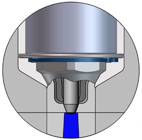
H       O       T              R       U   N    N      E     R           T     E      C     H     N      O     L      O     G      Y
                          Hot Runner Guide

                                                                           Layout and Design

   The purpose of this Hot Runner Guide                              The Hot Runner Guide - Layout and Design is intended to help everyone who designs feed systems
                                                                     for injection molds or simply wants to find out about designing feed systems in the following way:

                                                                     à Overview of the Synventive hot runner product range
                                                                     à Insight into the layout of feed systems with hot runner technology
                                                                     à Help to select suitable hot runner components

    Important note                                                   All the information contained in these pages is based upon our current knowledge and experience
                                                                     gained from both theory and practise. However because of many factors outside our control they do
                                                                     not guarantee the suitability of our products for any particular application. Always consult Synventive
                                                                     for your specific application.

    Table of Contents                                                Introduction

    Page 3 ..................................................             The Custom Hot Runner Solution from Modular Components

                                                                     Hot Runner Components

                                                                          Nozzles
    Page 4 ..................................................             Overview of Nozzles Series
    Page 5 ..................................................             Key Nozzle Data
                                                                          Manifolds
    Page 6 ..................................................             Basic manifold Dimensions
                                                                          Flow Control
    Page 7 ..................................................             Actuators

                                                                     Material Suitability

    Page 8 ..................................................             Nozzle Tip Description VTP Series
    Page 9 ..................................................             Nozzle Tip Description VSP Series
    Page 10 ..................................................            Nozzle Tip Description VSW, VTW Series
    Page 11 ..................................................            Nozzle Tip Description TTP, TTW Series
    Page 12 ..................................................            Nozzle Tip Description TFP Series

                                                                     Tip Modifications

    Page 13 .................................................             Tip Modifications VSP, VSW Series
    Page 14..................................................             Tip Modifications VTP, VTW Series
    Page 15..................................................             Tip Modifications TTP, TTW, TFP Series

                                                                     Hot Runner Design

    Page 16 ..................................................            Shot Weight per Nozzle
    Page 17 ..................................................            Thermal Expansion Guidelines

Master Language is English                                                    CAT-14-0001_EN-REV10                        For a specific application, please consult Synventive
© 2019 Synventive Molding Solutions.                                                     2 / 18                               All rights reserved. Errors and omissions excepted.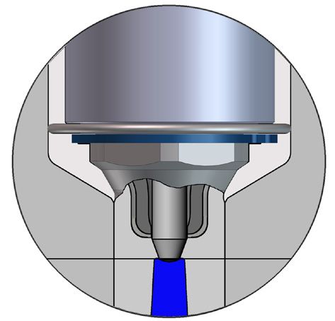
H O T R U N N E R T E C H N O L O G Y
Hot Runner Guide
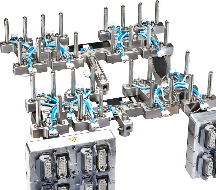
The Custom Hot Runner Solution from Modular Components
Hot Runner Components a)
1
b)
c)
Product Range Structure
d)
Hot runner systems may comprise of many
subsets, each customized for a specific
application.
a) Nozzles
Wide range of nozzles to suit most applica-
tions.
b) Hot Runner Systems
Available in standard shapes - I, H, X, Y - and e)
in any realisable custom shape, the ranges of
manifolds cover all possible injection configu-
rations and mold concepts.
3
c) Melt Flow Control Technology
Utilizing valve gate technologies, Synventive
provides solutions from traditional SVG to
activeGate® technology to meet the needs of
the most challenging applications.
d) Connections
To customer specification or Synventive
standard, Synventive hot runner systems
are available pre-wired, pre-plumbed and
pre-tested.
e) Hot Halves
Hot runner systems are supplied completely
mounted in mold plates, pre-wired, pre-piped
if required and fully adjusted.
Master Language is English CAT-14-0001_EN-REV10 For a specific application, please consult Synventive
© 2019 Synventive Molding Solutions. 3 / 18 All rights reserved. Errors and omissions excepted.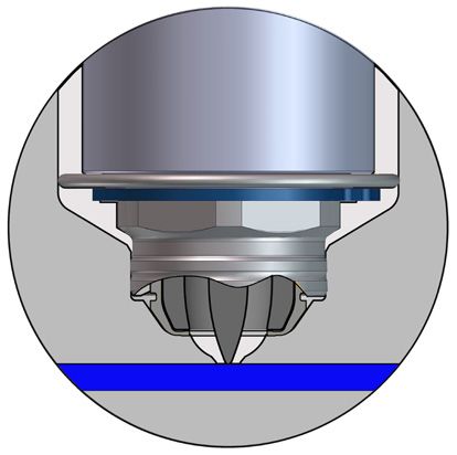
H      O    T         R     U   N   N     E    R           T     E     C    H     N      O     L      O     G       Y
                      Hot Runner Guide

                                                      Overview of Nozzle Series

 Nozzle style

 Nozzle size

                  J

                                 Sprue bushings                  Single axis valve gate nozzles             Threaded nozzles
                                 (thermal gate)                  (pneumatic / hydraulic)                    (thermal gate / valve gate)
                J=Ø6
   06

                                 06 S                                                                       06 E

                J=Ø9
   09

                                                                 09SVP
                                 09 S                            pneumatic                                  09 E01

                J=Ø12
   12

                                                                 12SVP
                                                                 pneumatic

                                 12 S                                                                       12 E
                                                                 12SVH
                                                                 hydraulic
                J=Ø16
   16

                                                                 16SVP
                                                                 pneumatic

                                 16 S                                                                       16 E
                                                                 16SVH
                                                                 hydraulic
   12    16

                                                                                                            12 EX 16

                J=Ø22
  22

                                 22 S                                                                       22 E

   16    22

                                                                                                            16 EX 22

Master Language is English                                    CAT-14-0001_EN-REV10                    For a specific application, please consult Synventive
© 2019 Synventive Molding Solutions.                                  4 / 18                             All rights reserved. Errors and omissions excepted.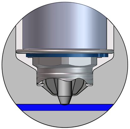
H O T R U N N E R T E C H N O L O G Y
Hot Runner Guide
Key Nozzle Data
Key nozzle data Max. shot weight per nozzle (g) Major Dimensions
Nozzle style Thermal gate Valve Gate *Thermal Gate
mediumb)
mediumb)
Nozzle series
higha)
higha)
lowc)
lowc)
J L D Xn Xc
S 06 S ………………… 30 70 120 - - - Ø6 60…200 Ø20 - -
09 S ………………… 70 120 250 - - - Ø9 60…400 Ø27 - -
12 S ………………… 500 800 1500 - - - Ø12 60…650 Ø35 - -
16 S ………………… 1000 1500 2000 - - - Ø16 96…627 Ø50 - -
22 S ………………… 1500 2500 5000 - - - Ø22 96…627 Ø60 - -
09 SVP pneumatic ………………… - - - 10 50 80 Ø9 50…400 Ø27 - -
12 SVP pneumatic ………………… - - - 80 150 300 Ø12 50…400 Ø35 - -
12 SVH hydraulic ………………… - - - 80 150 300 Ø12 50…400 Ø35 - -
16 SVP pneumatic ………………… - - - 250 600 1500 Ø16 100…395 Ø50 - -
16 SVH hydraulic ………………… - - - 250 600 1500 Ø16 100…395 Ø50 - -
E 06 E-02 ………………… 30 70 120 10 45 80 Ø6 60…200 Ø20 20 22,5
09 E ………………… 70 120 250 40 80 120 Ø9 60…400 Ø27 27 28,5
12 E-04 ………………… 500 800 1500 100 250 500 Ø12 96…627 Ø35 35 35,5
12 E-05 ………………… 500 800 1500 100 250 500 Ø12 96…627 Ø40 42 39
16 E-04 ………………… 1000 1500 2500 500 800 1500 Ø16 96…627 Ø50 50 48
12 EX 16-01 ………………… 700 1000 2000 250 450 1000 Ø12 - Ø16 196…647 Ø50 50 48
12 EX 16-02 ………………… 700 1000 2000 250 450 1000 Ø12 - Ø16 196…647 Ø50 52 49
22 E-04 ………………… 1500 2500 5000 800 1200 2000 Ø22 96…627 Ø60 60 53
16 EX 22-01 ………………… 1200 2000 3500 650 1000 1700 Ø16 - Ø22 196…647 Ø60 60 53
16 EX 22-02 ………………… 1200 2000 3500 650 1000 1700 Ø16 - Ø22 196…647 Ø60 60 53
S
*Thermal Gate nozzle related minimal distance (theoretical)
Xn minimal distance between nozzles
Xc minimal distance between nozzle and center support
S
Viscosity of melt L
(at medium melt tempera- B M A
ture and at a shear rate of
1000 1/s)
> 150 Pa s a) high J
Shot weight based on gating type and PC, PMMA PEEK, PES,
L
viscosity of melt PSU, PEI, POM
B M A
= 60...150 Pa s b) medium E
Major dimensions and heater zones ABS, SAN, ASA, PBT, PET, Xc
POM (Copo), PA, PPE, PPO,
J
PPS, PC/ABS, PC/PBT D
Xn
< 60 Pa s c) low
PP, PE, PS, LCP, TPE
E L
Xc
D
Xn
L
Master Language is English CAT-14-0001_EN-REV10 For a specific application, please consult Synventive
© 2019 Synventive Molding Solutions. 5 / 18 All rights reserved. Errors and omissions excepted.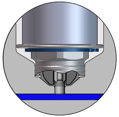
H        O     T            R      U     N      N        E        R             T         E     C    H       N      O     L       O    G      Y
                     Hot Runner Guide

                                                                  Basic Manifold Dimensions

Available manifold series                            V-37                V-42                    V-45                      V-50                     V-55                V-65
                                                 M=    M1=              M=    M1=               M=       M1=             M=   M1=              M=    M1=           M=    M1=
                            Nozzle size          37    36               42    50                45       50              50   60               55    70            65    80
                            Nozzle series   J2 max.             J2 max.                  J2 max.                     J2 max.            J2 max.              J2 max.
                                            NT V A            B NT V A                 B NT V A                    B NT V A           B NT V A             B NT V A            B

 06       06 E               ……             10   10    10    15

 09       09 E               ……                                    10            10 15 12 12 10 15

 12       12 E               ……                                                                                      12 12 15 15

 16       16 E               ……                                                                                                            16 16 20 20
          12 EX 16           ……                                                                                                            16 16 20 20

 22       22 E               ……                                                                                                                                 26 26 20 20
          16 EX 22           ……                                                                                                                                 26 26 20 20

                                                 NT:         Open nozzles                                V:          Valve gate nozzles

                                                                             B
                                                                                           A
           Major dimensions                                                       J2

                                                                        M

                                                                         M1

Master Language is English                                               CAT-14-0001_EN-REV10                                 For a specific application, please consult Synventive
© 2019 Synventive Molding Solutions.                                                   6 / 18                                       All rights reserved. Errors and omissions excepted.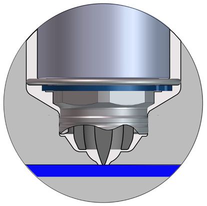
H O T R U N N E R T E C H N O L O G Y
Hot Runner Guide
Actuators
a hydraulic pneumatic electric
HYC4520M
PNC3008B
PNC4508B
PNC6018B
ELA7616M
ELA4308P
ELA5708P
ELA8708P
Actuators
VP4008P
VP8016P
HYZ3908
QCVG16
HB2508
HB4016
PB4008
PB6016
PB8016
Nozzle Nozzle Xc Xc Xc Xc Xc Xc Xc Xc Xc Xc Xc Xc Xc Xc Xc Xc Xc
size series
06 06 E - 38 - - 42 - - 61 55 - 45 60 - -
09 09 E - 38 61 53 - - 61 - 61 77 97 55 - - - 90
12 12 E 96 61 - 100 - - 76 77 97 - 97 - - - x*
16 16 E 140 61 - 100 - - 76 97 - 97 - - - x*
12 EX 16 140 61 - 100 - - 76 97 - 97 - - - -
22 22 E 140 61 - 100 - - - 97 - 97 - - - x*
16 EX 22 140 61 - 100 - - - 97 - 97 - - - -
* Reference, eGate 2.0 For Medium-to-Large Part Molding, Catalog CAT-16-0039_EN-Rev##
Actuator bolted to the manifold Actuator in mold plate
HB Series HYZ Series
PB Series QCVG Series
Xc
ELA M Series VP Series
Actuator with backing plate Electric actuator in mold plate
PNC####B Series ELA P Series
Xc Xc
Master Language is English CAT-14-0001_EN-REV10 For a specific application, please consult Synventive
© 2019 Synventive Molding Solutions. 7 / 18 All rights reserved. Errors and omissions excepted.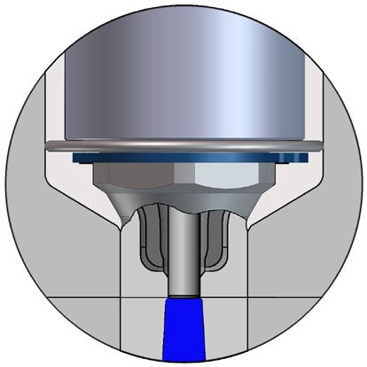
H       O    T    R   U    N      N      E       R         T       E    C     H        N     O      L     O     G      Y
                     Hot Runner Guide

                                                Nozzle Tip Description - VTP

   Nozzle Tip Selection

   From the nozzle tip descriptions, individual configurations can be selection to suit a specific application.

                                                 VTP
                                                 Valve Gate - Tapered Pin - Plunged Through

                                                 F=0, F=30, F= 0-30 MOD
                                                 Universal tip
                                                 For direct gating or cold runner applications
                                                 Recommended for all common polyolefin and amorphous resins
                                                 Talc filled resins
                                                 GF not recommended
                                                 Inner part made of heat conductive material
                                                 Melt is covered and controlled until gate
                                                 Tip face must always be against plastic to avoid heat loss and mechanical loads when closing mold
                                                 Wall thickness in gating area >= Gate-diameter
                                                 Industrial standard for head and rear lamp applications
                                                 Gate quality lower than straight needle, risk of flash
                                                 Unsuitable for cosmetic gating and amorphous plastics when direct gating on part
                                                 Non-homogeneous cavity surface temperature
                                                 Significant effect with slow needle opening, strongly recommended for activeGate®

                                                 VTP-SC
                                                 Most effective solution for color change applications
                                                 Slightly hotter tip surface than VTP
                                                 Flame retardant resins

Master Language is English                                 CAT-14-0001_EN-REV10                           For a specific application, please consult Synventive
© 2019 Synventive Molding Solutions.                                  8 / 18                                 All rights reserved. Errors and omissions excepted.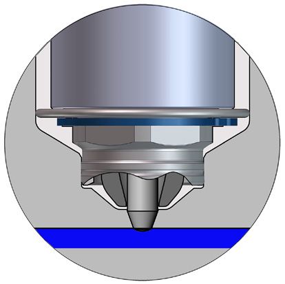
H       O    T    R   U   N     N      E       R          T      E    C    H     N      O     L     O     G      Y
                     Hot Runner Guide

                                               Nozzle Tip Description - VSP

                                               VSP
                                               Valve Gate - Straight Pin - Plunged Through

                                               F=0, F=30, F= 0-30 MOD
                                               Universal tip
                                               For direct gating or cold runner applications.
                                               For all common resins
                                               Talc filled resins
                                               GF< 30% crystalline; PA6.6 GF= Gate-diameter
                                               Gate quality better than tapered needle

                                               Unsuitable for cosmetic gating and amorphous plastics when direct gating on part
                                               Non-homogeneous cavity surface temperature
                                               No significant effect with slow needle opening (activeGate)

                                               VSP-SC
                                               For color change applications
                                               Flame retardant resins
                                               Slightly hotter tip surface than VSP

                                               VSP-WC Wear C
                                               External component – best possible wear resistance (abrasion and corrosion) with a standard heat
                                               transfer rate
                                               Internal component – high heat transfer rate
                                               GF>30% crystalline; PA6.6 GF>20%; LGF

Master Language is English                               CAT-14-0001_EN-REV10                       For a specific application, please consult Synventive
© 2019 Synventive Molding Solutions.                                9 / 18                             All rights reserved. Errors and omissions excepted.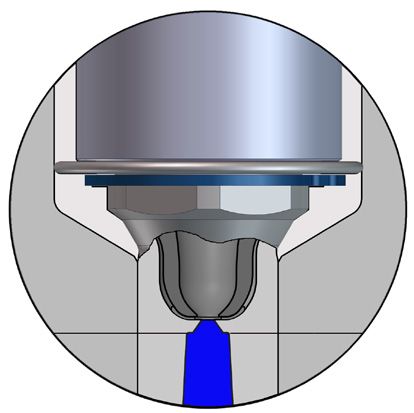
H       O    T    R   U   N     N      E       R         T    E       C    H     N       O      L     O     G      Y
                     Hot Runner Guide

                                           Nozzle Tip Description - VSW, VTW

                                               VSW
                                               Valve Gate - Straight Pin - Blind

                                               Inner part made of heat conductive material
                                               Melt is covered and controlled until gate
                                               For direct gating and cold runner applications
                                               Recommended for most common resins
                                               Wear and/or Cooling insert strongly recommended
                                               Talc filled resins
                                               GF < 20%(crystalline materials) GF
H O T R U N N E R T E C H N O L O G Y
Hot Runner Guide
Nozzle Tip Description - TTP, TTW
TTP
Thermal Gate - Torpedo – Plunged Through
All Tips F=0, F=30, F= 0-30 MOD
Inner part made of heat conductive material
Melt is covered and controlled until gate
Tip face must always be against plastic to avoid heat loss and mechanical loads when closing mold
For direct gating and cold runner applications
For most common resins recommended
Sprue as short as possible
Talc filled resins
GF < 20% (crystalline materials) GF30%) full flow or valve gate recommended
TTP-SC
For color change applications, if thermal gate is requested
Slightly hotter tip surface than TTP
Flame retardant resins
TTW
Thermal Gate - Torpedo - Blind
Inner component made of heat conductive material
Melt is covered and controlled until gate
For direct gating and cold runner applications
For most common resins recommended
Talc filled resins
GF < 20% (crystalline materials) GF30%) full flow or valve gate recommended
TTW-SC
Most effective solution for color change applications, if thermal gate and blind tip is requested
Slightly hotter cavity surface than TTW
Flame retardant resins
Master Language is English CAT-14-0001_EN-REV10 For a specific application, please consult Synventive
© 2019 Synventive Molding Solutions. 11 / 18 All rights reserved. Errors and omissions excepted.H O T R U N N E R T E C H N O L O G Y
Hot Runner Guide
Nozzle Tip Description - TFP
TFP
Thermal Gate – Full Flow – Plunged Through
All Tips F=0, F=30, F= 0-30 MOD
Inner part made of heat conductive material
Melt is covered and controlled until gate
Tip face must always be against plastic to avoid heat loss and mechanical loads when closing mold
For shear sensitive resins, with do not tend to string
For cold runner applications
Suitable for highly filled resins
Talc filled resins
Limited for direct gating because of possible gate vestige
Sprue as short as possible
Unsuitable for cosmetic gating
Gate tends to string
Gate vestige not defined
Non-homogeneous cavity surface temperature
TFP-SC
Best solution for color change applications, if valve gate is not necessary and gating at cold runner
Slightly hotter tip surface than TFP
Flame retardant resins
Master Language is English CAT-14-0001_EN-REV10 For a specific application, please consult Synventive
© 2019 Synventive Molding Solutions. 12 / 18 All rights reserved. Errors and omissions excepted.H O T R U N N E R T E C H N O L O G Y
Hot Runner Guide
Tip Modifications 12E, 16E, 22E Series
Illustrations simplified, schematically drawn and not to scale.
VSP
Standard Alternate Cutout
Space Restrictions, Contoured
or Angled Parting Line
Angled Gating Angled Gating Angled Gating Angled Gating
Option 1 Option 2 Option 3 Needle modification
Angle max 10° (recom.) Angle max 25° (recom.) Angle >25° NOT applicable
Extended land tip orifice Consult Synventive
with Valve Pin to accommodate
VSW
Angled Gating Angled Gating Angled Gating Angled Gating
Angle to part Option 1 Option 2 Option 3
Angle max 10° (recom.) Angle max 10° (recom.) Angle >10°
Valve pin +1,5 mm Consult Synventive
Consult Synventive
Preferred Available Not Available
Master Language is English CAT-14-0001_EN-REV10 For a specific application, please consult Synventive
© 2019 Synventive Molding Solutions. 13 / 18 All rights reserved. Errors and omissions excepted.H O T R U N N E R T E C H N O L O G Y
Hot Runner Guide
Tip Modifications 12E, 16E, 22E Series
Illustrations simplified, schematically drawn and not to scale.
VTP
Standard Alternate Cutout
Space Restrictions, Contoured
or Angled Parting Line
Angled Gating Angled Gating
Option 1 Option 2
Angle max 10° (recom.) Angle max 25° (recom.)
Extended land tip orifice with
reduced orifice and Valve Pin
to accommodate.
Tappered pin extended =
special part
VTW
Angled Gating Angled Gating Angled Gating
Angle to part Option 1 Option 2
Angle max 10° (recom.) Angle max 10° (recom.)
Tappered pin extended =
special part
Preferred Available Not Available
Master Language is English CAT-14-0001_EN-REV10 For a specific application, please consult Synventive
© 2019 Synventive Molding Solutions. 14 / 18 All rights reserved. Errors and omissions excepted.H O T R U N N E R T E C H N O L O G Y
Hot Runner Guide
Tip Modifications 12E, 16E, 22E Series
Illustrations simplified, schematically drawn and not to scale.
TTP
Standard Alternate Cutout Dimple
Space Restrictions, Contoured According to customer
or Angled Parting Line specification depth max. 1 mm
Angled Gating Angled Gating
Angle to part Option 1
Angle max 10° (recom.)
TTW
Angled Gating Angled Gating
Angle to part Option 1
Angle max 10° (recom)
TFP
Standard Alternate Cutout Dimple Angled Gating Angled Gating
Space Restrictions, Contoured According to customer Angle to part Option 1
or Angled Parting Line specification depth max. 1 mm Angle max 10° (recom.)
Preferred Available Not Available
Master Language is English CAT-14-0001_EN-REV10 For a specific application, please consult Synventive
© 2019 Synventive Molding Solutions. 15 / 18 All rights reserved. Errors and omissions excepted.H O T R U N N E R T E C H N O L O G Y
Hot Runner Guide
Shot Weight per Nozzle
The term “maximum shot size per nozzle” denotes
the performance capacity of a hot runner nozzle, 1
that is, the maximum quantity of plastic melt that
can pass through the nozzle during operation
without damaging the nozzle or plastic material.
The reason performance capacity is specified in
terms of weight rather than volume flow is that it is
more readily understandable to the user, who has
usually received information on the weight of the W W = + +
molded parts to be produced.
How to find the shot weight per nozzle (W) is
shown on the right for three different applications.
Several parts per nozzle
Multi cavity mold with sprue bushing
Gating on cold sub runner
Shot weight per nozzle = Parts + runner
2
One part per nozzle
Multi cavity mold with manifold system
Direct gating on to the part W1
Shot weight per nozzle = part
W1 = W2 =
Several nozzles per part
Single cavity mold with manifold system
Direct gating on to the part W2
Shot weight per nozzle = Section of the
cavity which is filled by one nozzle
The maximum shot size that can be
achieved depends on several factors:
à Injection time
à Type of plastic: viscosity, additives, etc. 3
à Runner length/diameter
à Maximum permitted pressure loss
à Residence time
When the above factors are taken into
consideration, conflicting requirements may W1
arise in some cases.
W1 =
Flow channel as big as possible:
W2 W2 =
à Iow pressure loss
à low shear rate
Flow channel as small as possible: W3 =
à Iow residence time W3
à good melt exchange
The values for the maximum shot weight of
a Synventive nozzle have been derived from
practical experience as well as theoretical
studies. They are valid for non-filled materi-
als. For a specific application, please always
consult Synventive.
Master Language is English CAT-14-0001_EN-REV10 For a specific application, please consult Synventive
© 2019 Synventive Molding Solutions. 16 / 18 All rights reserved. Errors and omissions excepted.H O T R U N N E R T E C H N O L O G Y
Hot Runner Guide
Thermal Expansion Guidelines
Ratio of Pitch Dimension to Nozzle length for threaded Nozzles
The thermal expansion of the manifold makes the nozzle move while the nozzle tip is fixed inside the mold cutout. In order to allow the nozzle to bend
without being damaged the nozzle must adhere to a minimum length. These graphs show the minimum length of threaded nozzles in relation to its pitch
dimension.
NOTICE
06E max length is 200 mm
09E max length is 400 mm
06E & 09E min. length 60 mm
Suitable pitch dimensions for
06E & 09E Nozzles
Suitable pitch dimensions for
09E Nozzles only
NOTICE
12E04 min. length is 60 mm
16E & 22E min. length is 110 mm
12E04, 16E & 22E
max. length 650 mm
Suitable pitch dimensions for
12E04, 16E & 22E Nozzles
Suitable pitch dimensions for
12E04 Nozzles only
Master Language is English CAT-14-0001_EN-REV10 For a specific application, please consult Synventive
© 2019 Synventive Molding Solutions. 17 / 18 All rights reserved. Errors and omissions excepted.www.synventive.com North America Synventive Molding Solutions Inc. 10 Centennial Drive Peabody, MA 01960, USA Tel.: +1 978 750 8065 Fax: +1 978 646 3600 E-Mail: info@synventive.com Europe Synventive Molding Solutions GmbH Heimrodstr. 10 64625 Bensheim, Germany Tel.: +49 (0) 6251 / 9332-0 Fax: +49 (0) 6251 / 9332-90 E-Mail: infohrde@synventive.com Asia Synventive Molding Solutions (Suzhou) Co.Ltd. 12B Gang Tian Industrial Square Suzhou Industrial Park, China 215021 Tel.: +86 512 6283 8870 Fax: +86 512 6283 8890 E-Mail: infohrcn@synventive.com CAT-14-0001_EN-REV10 2019-Mar-05 © 2019 Synventive Molding Solutions DTP: KA
You can also read