Hydraulic Switch Tamper - (HST) - Operation and Maintenance Manual
←
→
Page content transcription
If your browser does not render page correctly, please read the page content below
Hydraulic Switch Tamper
                                        (HST)

                                                          Operation and
                                                           Maintenance
                                                                Manual
                                                         Reorder Part: NES50-01
                                                           Last Revision: Rev. B
                                                              FEBRUARY 2014

Read and fully understand the precautions contained in this manual before operating
   or servicing this machine. Refer to Section 1 for important safety information.

Component Troubleshooting can now be found on the colored pages behind each tab.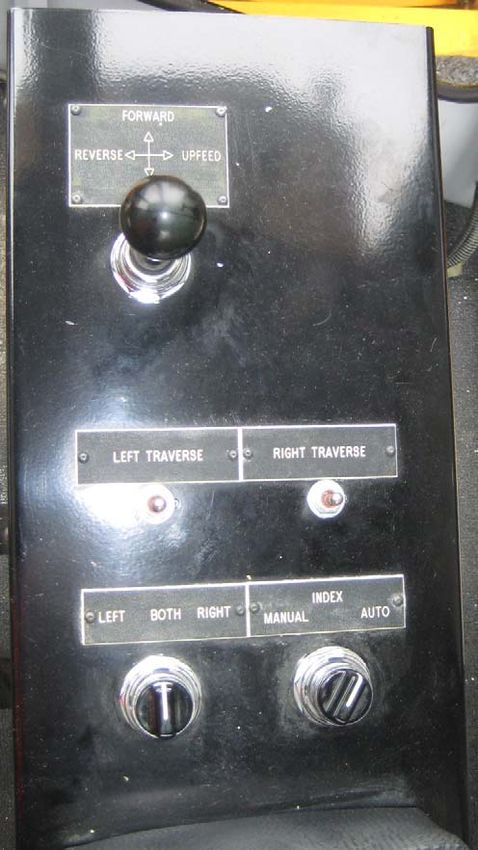
Release/Revisions
Release/Rev   Date        Change Description
Rev. A        2011        First Release
Rev. B        2/15/2014   Updates to the Work Travel and Parking Brakes
                          section under Pre-Operation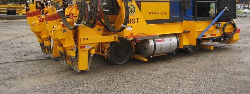
This manual is a guide for the operation and routine maintenance of a NORDCO Equipment Services
Machine. It covers product technical information, basic operating and maintenance procedures, and
safety information and is provided for use by the qualified personnel who will supervise, operate or service
the equipment described herein.

Measurements in this manual are given in both metric and customary U.S. unit equivalents.

Personnel responsible for the operation and maintenance of this equipment should thoroughly study the
manual before commencing operation or maintenance procedures.

                     This manual should be considered a permanent part of your machine and should
                     remain with the machine at all times.

                     Additional copies of this manual are available either as a part (Operation Manual
                     only) or a whole (operation and parts manual), at a nominal cost, through our Part
                     Sales Department. Additional service information, parts, and application information
                     is available through these Nordco product support resources:

We ask that if you have any comments or suggestions about this manual, let us hear from you. We are
here to be of service to you, our customers. Direct your comments and inquiries to:

                                           Customer Service
                                        107 North US Highway 45
                                            Arcola, IL 61910
                                             217-268-4823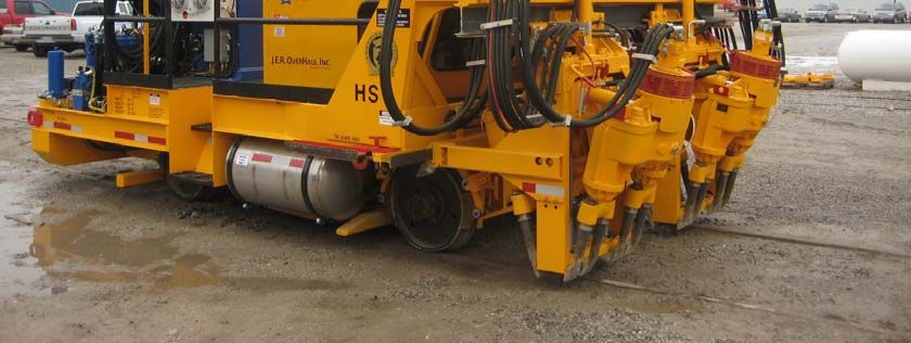
HAZARDOUS MATERIAL DATA

In an effort to provide information necessary for your employee safety training program and to meet the
requirements of OSHA Hazard Communication Standard 1910.1200, we have OSHA Form 20 Safety Data
Sheets available that cover the material contained in this machine.

If you are interested in receiving this information, please refer to the Name, model, and Serial Number of
your machine when calling or writing, and direct your inquiries to:

                                           Customer Service
                                        107 North US Highway 45
                                            Arcola, IL 61910
                                             217-268-4823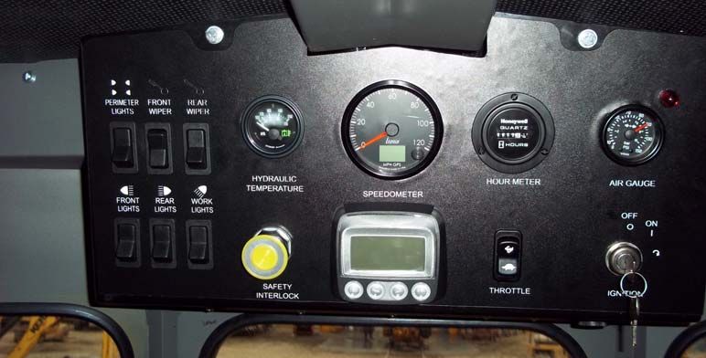
Hydraulic Switch Tamper (HST)                                                         SAFETY
                 SAFETY
 Please read and comply with all of the
 safety precautions in this manual BEFORE
 operating this machine.

 GENERAL                                       WARNING       indicates    a    potentially
                                               hazardous situation which, if not avoided,
 DO NOT use this machine for machine           COULD result in severe bodily harm or
 operations other than for which it was        even death.
 intended.

 NORDCO EQUIPMENT SERVICES (NES)
 is not responsible for any modifications
 made without authorization or written
 approval.        Replace all NORDCO           CAUTION       indicates   a     potentially
 EQUIPMENT SERVICES (NES) and OEM              hazardous situation which, if not avoided,
 parts with genuine NORDCO EQUIPMENT           MAY result in minor or moderate injury.
 SERVICES (NES) or OEM parts. Use of
 non-OEM parts could compromise the
 safety of your machine.

 FRA regulations require that a copy of this
 Operation Manual be kept on the machine
 at all times. Additional copies of the        CAUTION without the safety “!” means that
 Operation Manual only can be ordered          failure to follow the alert may result in
 from NORDCO EQUIPMENT SERVICES                machine damage.
 (NES) Customer Service at 1-217-268-
 4823.

 FOLLOW SAFETY INSTRUCTIONS

 Carefully read all safety messages in this    SAFETY means that the following points
 manual.      Learn how to operate the         are instructions for safely operating the
 machine and how to use controls properly.     machine or the specific component of the
  Do not let anyone operate this machine       machine.
 without instruction. Failure to understand
 the contents of this manual could result in
 serious personal injury or death.

  SAFETY ALERT SYMBOLS!

  These are the safety-alert symbols.
      These symbols means pay
   attention! Your safety is at risk!

 DANGER is used to indicate a definite
 hazardous situation which, if not avoided,
 WILL result in severe bodily harm or even
 death.

AUGUST/2011 (NES50-001)                                                                      Section 1-1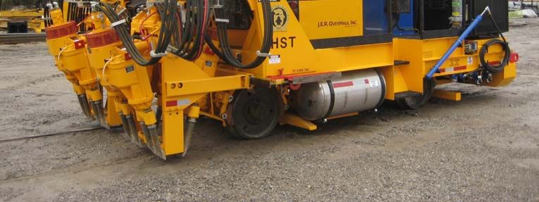
SAFETY                                                       Hydraulic Switch Tamper (HST)

  GENERAL SAFETY TIPS                                 obstructions and personnel.
                                                  •   Use care when climbing onto the
  Only trained and authorized personnel               machine. Always use the steps
  should be allowed to operate this machine.          and handrails provided. (If an area
   In addition, all personnel at the worksite         does not have tread grips,
  (gang) should be aware of the safety                walkways, or other methods to
  concerns        and     their     individual        access the area, then DO NOT
  responsibilities prior to working this              attempt to access that area.)
  machine.                                        •   Make seat and control adjustments
                                                      PRIOR to starting the machine.
                                                      ALWAYS wear a seatbelt.
                                                  •   Know the weather forecast and
                                                      plan your work speeds accordingly.
  1.       Handle fuel safely. It is highly       •   There are guards on this machine.
           flammable     and     prolonged            These are to be removed ONLY
           breathing of fumes may cause               when service or maintenance is
           bodily harm.                               being performed on that area of
                                                      the machine. Make certain they
  2.       Prepare for emergencies. Keep a            have been re-installed PRIOR to
           first aid kit and fire extinguisher        starting the machine.
           handy.                                 •   Check and service the fire
                                                      extinguisher (if so provided) at
  3.       Protect against flying pieces of           regular intervals. Make certain all
           metal and debris by wearing safety         personnel are trained in its use.
           glasses.                                   Note - Non-use of fire extinguisher
                                                      still requires that it be recharged at
  4.       Wear good-fitting pants and shirt,         the interval stated on its last
           no baggy or loose clothing.                inspection notice.
                                                  •   Keep the stairs, cab entry platform
  5.       Protect your head and eyes from            and cab interior free and clear of
           flying debris by wearing a hard hat        ice, tools and personal items. Use
           and safety glasses.                        the optional accessories provided
                                                      on the machine (tool box, cup
  6.       Wear leather gloves to protect your        holder, coat hook, etc.) to properly
           hands from vibration or flying metal       store your gear.
           particles.                             •   Never climb onto the machine
                                                      while it is in motion.
  7.       Use safety-toed work boots.            •   There are lockups on this machine
                                                      that are used for both work and
  SAFETY PRIOR TO WORKING                             travel. These should be kept clear
                                                      and free of debris, grease, etc.
  All personnel at the worksite (gang) should         See       Lockup        section    for
  be aware of the safety concerns and their           instructions on their use.
  individual responsibilities prior to working    •   Inspect safety decals and replace
  this machine:                                       when they become unreadable or
                                                      are damaged.

       •   Review the operating instructions if
           you are unsure of anything.
       •   Use the “pre-operational checklist”
           to check the machine for obvious
           faults. Repair or replace as
           necessary PRIOR to operating the
           machine.
       •   Before climbing onto the machine,
           make certain the area around and
           under the machine is clear of

Section 1-2                                                              AUGUST/2011 (NES50-001)
Hydraulic Switch Tamper (HST)                                                          SAFETY
 SAFETY  WHILE          STARTING       THE     applied and the electrical interlock button
 MACHINE                                       has been activated. NEVER stop and park
                                               this machine on an incline unless the
 NORDCO EQUIPMENT SERVICES (NES)               machine wheels have been chocked.
 recommends the use of a Command
 position. This means that the machine is      SAFETY DURING MAINTENANCE
 never running unless someone is at or
 near the main control panel. To prevent       The following guidelines are suggested
 injury to personnel or damage to the          when performing maintenance:
 machine, it is highly recommended to:

                                                   1. Always chock the wheels
     1. Only start and operate the machine         2. Alert others in the area that service
        from the operator’s seat.                     or maintenance is being performed
                                                      on this machine.
     2. Use the “STARTUP Checklist” to             3. Become familiar with, and use,
        check the machine controls and                your company’s lockout/tagout
        gauges to make certain all                    procedures       when     performing
        systems are operating correctly.              maintenance on this machine.
                                                      See             LOCKOUT/TAGOUT
 SAFETY WHILE                                         REQUIREMENTS later in this
 OPERATING/TRAVELING                                  Safety Section for a chart on
                                                      energy sources located on this
                                                      machine.
 1. Never allow more riders than seats and         4. Do not start the engine if repairs or
    seatbelts allow. This machine was                 work is being performed alone.
    designed to be operated by one                    You should always have at least
    person.                                           two people working together if the
                                                      engine must be run during service.
 2. The machine is to be operated from                 One person needs to remain in
    the Operator’s seat only. Do NOT                  the command position (at the
    stand and operate this machine.                   controls), ready to stop the
                                                      machine and shut off engine if the
 3. Press the EMERGENCY STOP                          need arises.
    pushbutton on the LEFT ARM console             5. Collect oils and fuels and dispose
    in   emergencies      and potentially             of them properly.        There is a
    dangerous situations.                             danger of scalding when working
                                                      with engine oils.
 4. If personnel or bystanders are near the        6. Use only NORDCO EQUIPMENT
    machine during operation, give a                  SERVICES (NES) supplied repair
    warning signal using the air horn. If             parts for this machine. Use of
    they fail to respond to this warning,             non-OEM designed parts could
    stop operation immediately.                       comprise the integrity of this
                                                      machine.
 5. Slow down the work cycle and use               7. There are welding cautions on this
    slower travel speeds in congested or              machine. Pay attention to them
    populated areas.                                  PRIOR to welding.
                                                   8. Kits    supplied     by    NORDCO
 6. Halt work if visibility is poor. Strong           EQUIPMENT SERVICES (NES)
    rains, fog, and extremely dusty                   have welding instructions included.
    conditions can affect visibility in your           Welding of any components NOT
    work area. Wait for the weather to                of      NORDCO          EQUIPMENT
    improve before continuing work.                   SERVICES (NES) manufacture or
                                                      failure to follow these instructions
                                                      may affect the stability of this
 SAFETY WHILE PARKED                                  machine.

 When leaving a machine engine running,
 make certain that the parking brake is

AUGUST/2011 (NES50-001)                                                                       Section 1-3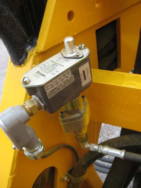
SAFETY                                                             Hydraulic Switch Tamper (HST)

                                                    otherwise. Failure to comply could result in
        MACHINE SAFETY                              personal injury and/or damage to the
           ALERTS                                   machine.

                                                    Exhaust emissions caused by the use of
                                                    the engine on this machine may cause
                                                    cancer, birth defects, or other reproductive
               DANGER ALERTS                        harm if inhaled.
   Improper use of this machine for any type
    of operation can cause serious injury or
                      death.                        Disconnect the battery before servicing this
  To avoid serious injury or death, make            machine. Failure to do so could result in
  certain that the area around and under the        personal injury from accidental engine
  machine is clear of all personnel and             startup.
  obstructions BEFORE travelling or working.
                                                    When machine is to be turned using the
  Serious injury or death can result from           turntable, raise machine only high enough
  reaching into working components while            for the wheels to clear the rail.
  machine is running. Make all observations
  from a distance and SHUT OFF machine                     MACHINE SAFETY ALERTS
  while making adjustments.
  Shut off engine when checking battery
  electrolyte level. Do not check or fill battery               CAUTION ALERTS
  in presence of open flame, sparks, or when
  smoking. Battery fumes are flammable                 NEVER START THE HYDRAULIC
  and/or explosive and if ignited will result in
                                                    VIBRATORS WHEN THE ENGINE IS AT
  severe bodily injury or death.
                                                    FULL THROTTLE. ALWAYS START at
  Do not ride on tow bar between the                 ENGINE IDLE OR DAMAGE TO THE
  machine and the towing vehicle. Falling            VIBRATOR MOTORS WILL OCCUR.
  from a moving vehicle may cause serious
  injury or death.                                  Never run vibrators with loose
                                                    tools as this will cause extreme
                                                    damage to the hole inside the
         MACHINE SAFETY ALERTS                      tool holder portion of the
                                                    vibrator.

              WARNING ALERTS

  Failure to engage all lockup devices before
  propelling at travel speed can result in
  injury to personnel and/or extensive
  damage to the machine.

  Remove hoses/fittings only when system is
  not pressurized. High pressure leaks can
  cause personal injury.

  Always turn off machine when performing
  maintenance, making adjustments, or
  whenever unintended movement of
  machine could occur; unless directed

Section 1-4                                                                    AUGUST/2011 (NES50-001)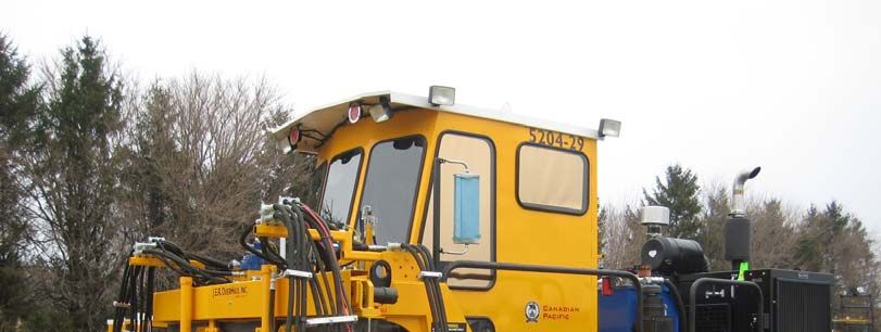
Hydraulic Switch Tamper (HST)                                                                      SAFETY

                                   LOCKOUT-TAGOUT PROCEDURES

      NORDCO has provided the means to lockout this machine. NORDCO cannot be held
     responsible for injury caused by failure to comply with your company’s Lockout/Tagout
                                            Procedures.
 The following procedures are designed to lead the operator through the steps required to shut the machine
 down and prepare it for performing mechanical maintenance work. These procedures are intended to release
 potentially dangerous stored energy forms and make the machine safe to begin repairs. It is your company’s
 responsibility to Lockout/Tagout Procedures based on this list, train you in their proper and safe use, and to
 periodically inspect your work area to verify that you are complying with the procedures. Lockout/Tagout
 Procedures must be followed!

                            SAFETY PROCEDURES
                                  LOCKOUT/TAGOUT
                 1. Apply the Electrical InterlocK at the Overhead control console.
                 2. Chock wheels to prevent accidental rolling of machine on grade.
                 3. If you have not already done so, determine which components are to
                    have maintenance. Place all machine mechanical systems or workheads
                    in the full up and locked positions.
                 4. When mechanical locking up of equipment is not feasible for
                    maintenance lower the component to the ground prior to working on the
                    equipment.
                 5. Turn the ignition switch to the OFF position. This turns off the power to
                    the control circuits on the machine. Place a TAGOUT card in close
                    proximity to the ignition switch.
                 6. Turn the battery disconnect switch (BDS) to the OFF position.
                         a. For machines with a remotely located BDS (usually next to the
                             battery box itself): Close the cover to the disconnect switch and
                             place a LOCKOUT lock on the box after you have switched it to
                             the OFF position.
                 7. Bleed off hydraulic pressure by slowly cracking hose fitting (1/8-1/4 of
                    turn CCW) at the cylinder/motor/pump of the hydraulic circuit being
                    worked on. Service or perform maintenance on circuit after the steady
                    flow of oil is gone.
                 8. Follow all of your company’s lockout/tagout rules before proceeding.
                    Note: When working on machine components, be aware that moving
                    components during repairs may create energy (ie., moving a hydraulic
                    cylinder). Proper precautions should be taken.

AUGUST/2011 (NES50-001)                                                                                Section 1-5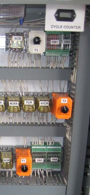
SAFETY                                                                       Hydraulic Switch Tamper (HST)

  HAZARD DECALS ON THIS MACHINE

  Hazard decals and plaques that have been placed on this machine are to be kept clean and legible.
  Replace any decals or plaques that have become illegible or are missing.

  When repairing or replacing components that had hazard decals on them, it is your responsibility to
  replace the decals. Refer to Figure 6-4 in the Mechanical Section for a list of all decals and plaques on
  this machine.

Section 1-6                                                                              AUGUST/2011 (NES50-001)
Hydraulic Switch Tamper (HST)                                                                     GENERAL
                                                    GENERAL

 This manual contains information for the Hydraulic Switch Tamper (HST). Throughout this manual,
 reference to Right Hand (R/H), Left Hand (L/H), and Front and Rear are all determined from the operator in the
 normal work position.

 Information is provided in this manual for operation and maintenance of the machine. Information regarding
 operation and maintenance of OEM parts not of Nordco Equipment Services manufacture can be found at the back
 of this manual, behind the tab marked “Component Data”.

 Become familiar with all safety instructions, controls and instruments before operating this machine. Follow
 all instructions carefully.

 ABOUT THIS MANUAL

 This manual has been broken down into sections which have been separated by index tabs:

      Mechanical has individual parts breakdown drawings and lists for each assembly

      Hydraulic includes adjustment instructions and troubleshooting for the hydraulic system; and all
      piping and functional drawings for a standard machine and optional equipment

      Electrical, includes electrical schematics, distribution and control boxes, and cabling drawings for the
      machine; as well as troubleshooting instructions

      Pneumatic, includes pneumatic schematics for the machine; as well as troubleshooting instructions

      Component Data includes parts breakdowns and service instructions for components installed on the
      machine that are not of Nordco Equipment Services manufacture. (Behind "Cylinders, Valves, Motors,
      Pumps, Engine, and Other" tabs.)

 All rights reserved. In view of the constant improvements to our equipment, the specification data and
 other technical information included in this manual are subject to change. No part of this manual may be
 reproduced in any form or by any means without our written permission.

AUGUST/2011 (NES50-001)                                                                                   Section 1-9
GENERAL Hydraulic Switch Tamper (HST)
SPECIFICATIONS
GENERAL
Weight..................................................................................................................... 28,000 Pounds (12.700 kg)
Length .................................................................................................................. 20 feet 6 inches (6.2 meters)
Width................................................................................................................... 10 feet 6 inches (3.18 meters)
Height.................................................................................................................. 10 feet 4 inches (3.10 meters)
Travel Speed on Rail ....................................................................... In excess of 35 mph (56 km/h) maximum
Rated Draw Bar Pull (On Rail) .......................................................................................... 15,000 lbs. (6803 kg)
Turntable .................................................................................................... Hydraulically Operated - Rail to Rail
Wheel Base ........................................................................................................................................................
Towing Speed ................................................................. 35 mph (56 km/h) maximum (See towing procedure)
CAPACITIES
Fuel Tank(Dual Connected Tanks) (two fify or two 75) ................................................ 160 Gallons ( 605 liters)
Hydraulic Oil Tank........................................................................ (180 or 220 gallons) 185 gallons (700 liters)
Oil Cooler ............................................................................................................................. 30 gpm (114 L/mn)
ENGINE
Make/Model ......................................................................................................... John Deere PE6068HF485
Continuous BHP ............................................................................................................. 175 HP @ 2200 RPM
Oil Capacity........................................................................................................................................ 32.5 Liters
HYDRAULIC SYSTEM
Pressure Settings:
Relief Valve - Track Drive ................................................................................................. 5000 psi (345 bar)
Main Pump (22 GPM) Mfr. ..................................................................................................................................
Relief Cartridge (Valve Banks) .................................................................................................... 2700 psi ( bar)
PNEUMATIC SYSTEM
Engine Mounted Compressor ................................................................................................. 14 cfm @ 120 psi
Unloading Valve ....................................................................................................................... 90 psi/110 psi
Relief Valve ............................................................................................................................................. 150 psi
Tanks ......................................................................................................................................... 2 @ 6.5 gallons
Air Dryer ................................................................................................................ C/R Turbo 2000, with Heater
ELECTRICAL SYSTEM
Battery.................................................................... 24V dc (Two 12-Volt Batteries), 1150 Cold Cranking Amps
Ground .................................................................................................................................................. Negative
Main Disconnect ................................................................................................................. Positive Disconnect
DRIVE SYSTEM
Drive Type.................................................................................................................................... Dual Axle Drive
Propulsion Type ......................................................................... Hydraulic Motor Driven, 4-Speed Transmission
AXLE/WHEELS
Axle Size ..................................................................................................................................................... 5-inch
Wheel Size and Type ............................................................................ 24 inch ( 60 cm) diameter, Forged Steel
Brakes
Indexing ................................................................................................................... 4 Wheel Hydro-Dynamic
Traveling ............................................................................................. Four Wheel Clasp Type with Fail Safe
Emergency & Parking .......................................................................................... Fail Safe Spring Take-Over
Items or capacities may vary according to options on your machine.
* Approximate weight. Actual weight may vary according to options on your machine. Actual weight of
your machine is as stenciled.
Section 1-10 AUGUST/2011 (NES50-001)Hydraulic Switch Tamper (HST) PRE-OPERATION
GENERAL Always use your seat belt when sitting in the
operator seat.
DO NOT use this machine for machine
operations other than for which it was intended. For additional information concerning the controls
used in the Operator’s Station refer to Cab
FRA regulations require that a copy of this Controls and Indicators later in this section.
Operation Manual be kept on the machine at all
times. Additional copies of the Operation Manual VIBRATOR AND WORKHEAD ASSEMBLY
only can be ordered from Nordco Equipment
Services (NES) Customer Service at 1-217-268-
4823.
Carefully read all safety messages in this manual
and on the decals located throughout the Motor
machine. Learn how to operate the machine and
how to use controls properly.
Fan
Do not let anyone operate this machine without
instruction. Failure to understand the contents of
this manual could result in serious personal injury
or death.
Vibrator
ABOUT THIS MACHINE
The HST is designed to tamp ballast both inside
and outside the rails, as well as through switches.
The HST is a workhorse designed for speed,
accuracy and dependability. The HST tamper Tool
enables you to tamp the entire switch area and
chase production machines very quickly and
accurately. Each workhead consists of a vibrator unit that
houses four tools. Each side of the machine has
The HST utilizes electric over hydraulic controls, a front and rear workhead that operates in sync
ergonomic operator station, four wheel drive and with each other. The operator can select whether
air operated clasp type brakes with failsafe he wants to run just the left or right sets or both at
feature on all four wheels. the same time.
The tamping cycle can be done either manually Once the machine hydraulics have warmed up,
or automatic. In the automatic mode of operation the vibrator units can be turned on.
the tamping cycle is as follows: vibrator on,
workhead down, tools close, tools open,
workhead up, and traction. Workheads can
operate separately or simultaneously. Start and stop vibrators at IDLE only.
Failure to do so will damage vibrator
motors.
OPERATOR’S STATION
The vibrators will vibrate the tools at
Almost all the controls for running this machine approximately 3200 vibrations per minute (3200
are located inside the cab. This includes but is vpm) with a maximum movement range of 3/8"
not limited to, the overhead control panel, the left (9.5mm). As the tool vibrates it lowers into the
and right arm controls, the main control panel,
ballast to a depth preselected by a DOWN limit
and propulsion and braking controls.
switch setting. (See Down Limit Switch in the
Under no circumstances are there to be more Setup Section of this Manual for more
riders on this machine than seatbelts available. information). When the maximum depth has
FEBUARY/2014 (NES50-001) Section 2-1PRE-OPERATION Hydraulic Switch Tamper (HST)
been reached, the front and rear workhead tools ELECTRICAL SYSTEM
"close" and compact the ballast under the tie.
The hydraulic functions of the machine are
controlled by the electrical system. The relays,
ENGINE limit switches, micro switches and timing modules
that make up the electrical system are shown on
Your machine is equipped with an automatic the schematics and wiring diagrams included in
shutdown system when low engine oil pressure the ELECTRICAL section of this manual.
and high engine coolant temperatures have been
reached. Before the machine reaches its CONTROLS AND INSTRUMENTS
shutdown levels, it will activate an audio and
visual alarm. Become thoroughly familiar with the function and
operation of all controls, as described in this
Your machine is also equipped with a shutdown section, before attempting to operate the
override system, which will allow you to override machine. However, the information in this section
a shutdown in the event of an emergency. This is intended to be for descriptive purposes only.
will give you time to move the machine to a Also read carefully the instructions in the
different location before shutting down the Operation section of this manual before
machine and attempting to troubleshoot the attempting to operate the machine.
engine problems. USE THIS SWITCH ONLY IN
THE EVENT OF AN EMERGENCY! NOTE:
Your machine may not have all the optional
controls and instruments that are described in this
section.
Section 2-2 FEBUARY/2014 (NES50-001)Hydraulic Switch Tamper (HST) PRE-OPERATION
Figure 1. Cab Controls and Indicators
Upper Front Console
Items may vary in location due to options installed
INSTRUMENT OR
CONTROL FUNCTIONAL DESCRIPTION
TRAVEL LIGHTS Light will illuminate in the direction selected when switch is in the ON position and will
remain lit until switch or machine has been turned off.
WORK LIGHTS Light will illuminate when switch is in the ON position and will remain lit until switch or
machine has been turned off.
PERIMETER LIGHTS Light will illuminate on the side of the machine selected when switch is in the ON
position and will remain lit until switch or machine has been turned off.
WIPERS On/Off, turns respective wiper assembly on or off.
HYDRAULIC Indicates temperature of oil in hydraulic reservoir. Normal operating temperature is
TEMPERATURE 80° to 180° F (49° to 72° C). Anything above that indicates possible problem with oil
GAUGE cooler.
AIR PRESSURE Measures air system pressure. Normal reading is 105 to 120 psi.
GAUGE
SPEEDOMETER Indicates travel speed of machine in both kilometers and miles per hour.
HOURMETER Block numbers on gauge indicate engine hours.
IGNITION SWITCH The electrical system is energized by turning the key to the right. Electrical power is
cut off and the engine will stop when the key is turned to the full left or vertical (OFF)
position.
ALARM Buzzer sounds on low oil pressure, and high coolant temperature.
THROTTLE Momentary switch used during work, travel, and shutdown. Hold switch in position until
(ENGINE SPEED desired engine RPM has been reached and then release switch.
SWITCH)
ELECTRICAL Shuts off Travel Power and all work power. You will still have lights, horns, radio
INTERLOCK functions, etc.
MURPHY DIAGNOSTIC See Next Page for more details. Refer to engine manual for error codes.
DISPLAY
FEBUARY/2014 (NES50-001) Section 2-3PRE-OPERATION Hydraulic Switch Tamper (HST)
Figure 1A. Cab Controls and Indicators
Upper Front Console
ENGINE DIAGNOSTIC GAUGE
(Upper Portion of Console)
Turn the ignition switch to the first detent (power will come on, but engine is not started) and wait.
The Powerview will come on, and a “WAIT TO START-PREHEAT” message will appear on the screen. A light (Wait
to Start) directly beneath the Powerview will turn on.
When the message disappears and the light goes out, it is safe to start the engine.
Instrument or Control Type of Control Functional Description
Menu Key The Menu Key is touched to either enter or exit the
menu screens.
The Menu key is only used during factory setup
procedures. (See Component Data Section for
additional operation and setup instructions.)
Left Arrow Use the left to move to the left or upward in a 4-Up
screen. You can use the left arrow at any time to
return to the previous screen.
Right Arrow Use the right arrow key to move to the right or
downward in a 4-Up screen, or to move to the next set
of 4 controls.
Enter Key The enter key is used when a fault occurs.
Generally, any fault that occurs will come up on the
screen at the time it happens. In order to go back
to the original status screen you have to push the
enter key once. NOTE: This will hide the fault
screen until you 1) correct the fault, or 2) you press
enter again.
Section 2-4 FEBUARY/2014 (NES50-001)Hydraulic Switch Tamper (HST) PRE-OPERATION
Instrument or Control Type of Control Functional Description
Warning Light Amber LED The Amber Warning LED signals an ACTIVE FAULT
code. When the light comes on, an abnormal
LED status lights are condition exists. It is not necessary to shut down
located on the upper the engine immediately, but problem should be
left and upper right corrected as soon as possible. This light will
sides of the powerview. remain on until all faults are corrected. Note: There
When they are lit, the may be more than one fault if
screen will tell you the appears at the bottom of the screen. You can also
fault, the code number hide the faults by hitting the ENTER key. (Hitting
for the fault, and the the enter key again will take you back to the fault).
method to correct the
fault. NOTE: Ignoring active fault codes (warnings or
shutdown) could result in severe engine damage.
Shutdown Derate Light Red LED The Red Shutdown Derate LED signals a fault has
occurred that requires immediate action. Shutdown
LED status lights are the engine, but do not turn the switch to the off
located on the upper position. You must go through the codes on the
left and upper right screen and correct the problems prior to restarting
sides of the powerview. the engine. (The Powerview remembers the errors).
When they are lit, the
screen will tell you the NOTE: Ignoring active fault codes (warnings or
fault, the code number shutdown) could result in severe engine damage.
for the fault, and the
method to correct the
fault.
Screen Display Used to monitor engine and engine controls.
HIDING FAULTS AND WARNINGS
If you have hidden (hit the ENTER key at any fault condition), and have returned to the original 4-Up (or 1-Up)
screen, the screen will now show icons in the upper right hand corner of a 1-UP screen or in the middle of the 4-UP
screen (see figure below) to show you where the faults occurred. (In the 4-up shown below, the exclamation point
appears in the middle and at the status that is showing a fault – the oil pressure.) Remember, the screen will show a
if more than one error has occurred.
Scroll through the screen until you find the individual component that has a fault.
Highlight the component and press the ENTER key to read the fault.
Each fault icon has a different meaning and different methods to correct. These are:
NOTE: Faults can only be cleared when the fault has been corrected.
SHUTDOWN MACHINE as soon as possible when you have encountered a
Shutdown Fault.
FEBUARY/2014 (NES50-001) Section 2-5PRE-OPERATION Hydraulic Switch Tamper (HST)
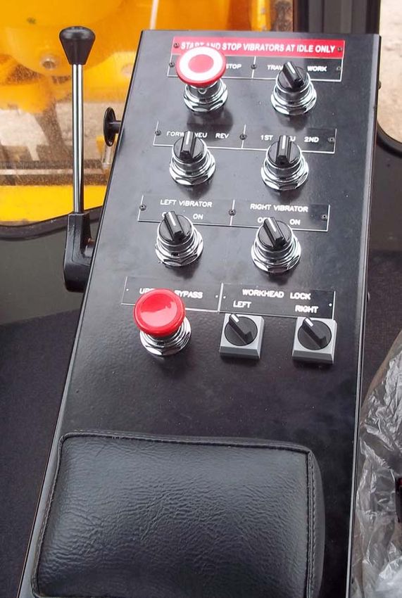
Figure 2. Cab Controls and Indicators
Left Arm Console
NOTE: Emergency Stop Button Has Been Added to
the LEFT ARM CONTROLS. This is to be used during emergency
situations only and should not be used as a method to routinely
shutdown the machine. PRESS to stop machine. PULL to begin
machine startup procedures.
Section 2-6 FEBUARY/2014 (NES50-001)Hydraulic Switch Tamper (HST) PRE-OPERATION
FUNCTIONAL DESCRIPTION
INSTRUMENT OR
CONTROL
TRAVEL/WORK MODE Two position rotary switch. When in travel mode, machine work functions are
SWITCH disabled. Travel Gears only 1st and 2nd.
Work Mode gets you low low. Machine MUST be in WORK mode during work
operations.
TRAVEL DIRECTION Three position rotary switch. Selects the desired direction of travel. In addition,
SWITCH
GEAR SELECT Three position rotary switch. Used only when in TRAVEL position.
SWITCH
1st Gear: Used for normal working operations.
2nd Gear: Used for high speed track travel.
STOP AND START VIBRATORS WHEN AT IDLE SPEEDS.
FAILURE TO FOLLOW THIS WILL CAUSE DAMAGE TO THE VIBRATOR MOTORS.
LEFT VIBRATOR Two position rotary switch. Turns left vibrator ON or OFF.
SWITCH
RIGHT VIBRATOR Two position rotary switch. Turns right vibrator ON or OFF.
SWITCH
UPFEED BYPASS
Bypasses the UP limit switches of the workhead. Used to store the workheads
BUTTON
in their locked position. Also used to clear rail when using traversing mode.
WORKHEAD LOCK Two position rotary switch. Used along with the Travel/Work Mode Switch.
SWITCH Used with upfeed bypass switch to raise the workheads prior to locking up.
When workheads are to be locked up, place machine in work mode and turn on
the locks.
SIDE AND FRONT CONTROLS
SERVICE BRAKE
Forward releases brakes
LEVER
PARKING BRAKE
Push/Pull. Must be applied at all times when the machine is stopped.
BUTTON
WARMUP SWITCH ON/OFF switch.
FEBUARY/2014 (NES50-001) Section 2-7PRE-OPERATION Hydraulic Switch Tamper (HST)
Figure 3. Cab Controls and Indicators
Right Arm Console
Section 2-8 FEBUARY/2014 (NES50-001)Hydraulic Switch Tamper (HST) PRE-OPERATION
FUNCTIONAL DESCRIPTION
INSTRUMENT OR
CONTROL
WORK CONTROL Used with the Travel/Work Switch in the WORK position:
JOYSTICK
Forward: Travel forward
Reverse (left): Reverse travel
Upfeed (right): Workheads come to "UP" position
Cycle (back) (or footswitch in Auto)
LEFT Traverse Two position momentary switch. Controls the left to right movement of the left
SWITCH vibrator workhead. Release switch once workhead has reached the desired
position.
RIGHT Traverse Two position momentary switch. Controls the left to right movement of theright
SWITCH vibrator workhead. Release switch once workhead has reached the desired
position.
WORKHEAD Three position rotary switch. Allows the operator to use either single workhead
SELECTION SWITCH functions or both workheads simulataneously.
INDEX SWITCH Allows manual or auto cycling of machine workheads.
FEBUARY/2014 (NES50-001) Section 2-9PRE-OPERATION Hydraulic Switch Tamper (HST)
Figure 3. Cab Controls and Indicators
Main Control Panel
(Right Cab Wall Behind Operator)
FUNCTIONAL DESCRIPTION
INSTRUMENT OR
CONTROL
12 VDC Power Provides source of 12V power to customer supplied equipment.
DOUBLE TAMP If double tamping is required, place this switch in the ON position and double tamping
SWITCH ON/OFF will always occur. Normal operation is with the switch in the OFF position.
TRACTION DELAY Traction delay is for Automatic Operation Only and can be initiated by turning on the
SWITCH ON/OFF traction delay switch. This switch works with T1 inside the control panel (see next
page).
ALARM AND LEDS
Alarm will sound when any of the four alarm states occur (turntable down, low
hydraulic oil, high hydraulic temps). These are separate from the alarm states issued
on the Murphy Diagnostic gauge.
Green LED for turntable indicates Turntable is raised.
Section 2-10 FEBUARY/2014 (NES50-001)Hydraulic Switch Tamper (HST) PRE-OPERATION
Figure 3. Cab Controls and Indicators
Inside Main Control Panel
(Right Cab Wall Behind Operator)
INSTRUMENT OR FUNCTIONAL DESCRIPTION
CONTROL
CYCLE COUNTER Used to keep track of daily work cycles.
TIMER 1 Adjusts the time delay from the time the workheads leave the lower limit switches
(T1) during up-feed in automatic mode and machine forward travel starts. This option is
TRACTION DELAY provided so the operator can adjust his indexing from tie to tie when working the
machine down a steep grade to allow the workheads to clear the ties. This timer only
works when the Traction Delay Switch is in the ON position.
TIMER 2 Adjusts the time delay between when the workheads go to an up position before
(T2) starting the cycle again. This timer relay is energized by the squeeze pressure switch.
DOUBLE TAMP This timer only works when the Double Tamp Switch is in the ON position.
TIMER 3 When activated it energizes CR6 turning on the pumps. When power is taken away,
(T3) the timer runs the determined time, then dropping out P1 and P2. Normal setting of
PUMP TIMER this timer should be around 3 seconds. (Timer is adjustable to 6 seconds).
FEBUARY/2014 (NES50-001) Section 2-11PRE-OPERATION Hydraulic Switch Tamper (HST)
TABLE OP-7
REMOTE CONTROLS AND INDICATORS
Section 2-12 FEBUARY/2014 (NES50-001)Hydraulic Switch Tamper (HST) PRE-OPERATION
Item Control or Instrument Function
1 Emergency Pump Located on frame between hydraulic tank and engine. Control switch
is located in box mounted to engine shroud above the Turbo 2000 Air
Dryer. Pump is used when there is a loss of system pressure and
movement of hydraulic cylinders is necessary. System pressure is
supplied by electric pump.
Top Off Pump The top off pump can be either an electric or manual pump that is
2 used for filling the hydraulic tank. Control switch for the electric
pump is located in box mounted to engine shroud above the Turbo
2000 Air Dryer. (Called Transfer Pump on Decal)
3 Battery Disconnect Switch Located next to the battery box. Two position switch marked with
"ON/OFF" plaque. This must be OFF and cover locked during
service.
4 Hydraulic Oil Tank Sight Located on hydraulic oil tank, it indicates the level of hydraulic oil in
Level the tank.
5 Air System Controls Air System Drain, Air Tanks Water Drain, Purge Tank Drain. Pull
cord to release.
6 Air Dryer Removes moisture from air in air system.
7 Fuel Filler Fill machine with fuel through opening.
8 Turntable Control Valve Used to lift the machine off track. Up/Down directional control valve.
Note: When turntable is raised, it MUST be locked up at all times.
FEBUARY/2014 (NES50-001) Section 2-13PRE-OPERATION Hydraulic Switch Tamper (HST)
WORKHEAD LOCK-UPS (REMOVAL)
FAILURE TO REMOVE ALL LOCKUP DEVICES BEFORE WORKING OPERATIONS CAN
RESULT IN INJURY TO PERSONNEL AND/OR DAMAGE TO THE MACHINE.
This machine Is equipped with a number of locking devices to insure the proper operation of the machine. For the
most part, these devices are used to make sure that certain moving parts remain secure while the machine is track
traveling. Engage all component lockups prior to track travel and through crossings, switches and frogs.
WORKHEAD LOCK
Traverse Extension
Workhead Lockup
UNLOCK WORKHEADS
a) At the Right Operator Seat Console, select "both" on the vibrator selector switch.
b) At the Left Operator Seat Console:
1. Push the "Up-feed By-pass" Pushbutton.
2. Place the Workhead Lock switch in the OFF position.
d) Activate the cycle lever which will cause both workheads to drop into the ballast.
e) At the Right Operator Seat Console, Move the joystick to the right to cause both workheads to "up-feed" and stop
on their respective upper limit switches.
NOTE: The HST’s are equipped with traverse extensions which permit the workheads to tamp the area outside of
each rail. Remove pin, swing out and insert pin for work position.
Section 2-14 FEBUARY/2014 (NES50-001)Hydraulic Switch Tamper (HST) PRE-OPERATION
TRAVERSE LOCKUP
Traverse Lockup
LOCKUP PROCEDURE USED
Pull down, twist 1/4 turn and run machine until workhead When transporting on truck. When
is centered. When workhead is properly centered pin tamping through super-elevations so
will enter and lock in correctly. that creep doesn't occur.
FEBUARY/2014 (NES50-001) Section 2-15PRE-OPERATION Hydraulic Switch Tamper (HST)
TURNTABLE LOCK-UPS (REMOVAL AND INSTALLATION)
FAILURE TO ENGAGE ALL LOCKUP DEVICES BEFORE PROPELLING AT TRAVEL SPEED
CAN RESULT IN INJURY TO PERSONNEL AND/OR DAMAGE TO THE MACHINE.
DO NOT CLIMB UNDER MACHINE WHEN IT IS RAISED ON TURNTABLE! THIS IS TO BE
USED AS A METHOD OF TURNING THE MACHINE AND IS NOT INTENDED TO BE USED
FOR MAINTENANCE OF ITEMS UNDER THE MACHINE.
Use the following procedures to install lock-ups. Note: With the exception of the suspension lockout, all lockups
are to be in place during track travel.
LOCKUP PROCEDURE USED
At any time when turntable
1. Machine must be in WORK mode is NOT being used.
and Warmup switch on front of LH
arm console must be in the ON
position.
2. Locate the Turntable Valve and
Turntable Lockup Box on the left
hand rear side of the machine
(below the air dryer).
3. Remove the red lockpin.
4. Pull black knob to unlock the
cylinder.
5. Lift handle slowly to raise the
machine, lower handle slowly to
lower machine. Machine will
remain in position when handle is
released.
6. Verify that the Turntable is in the
full UP position.
7. When turning is complete, lower
the machine to the rails, push in
the cylinder lock knob, and apply
the lock pin.
Section 2-16 FEBUARY/2014 (NES50-001)Hydraulic Switch Tamper (HST) PRE-OPERATION
Preparing the Machine for Work
As with any machine, pre-operational checks and
preventative maintenance should be performed
before using the machine. We suggest that you
follow the guidelines listed below before actually
operating the machine.
1. Position the machine on level track so
fluid levels can be accurately checked
and filled as necessary:
a. Check Engine Oil and Coolant
Levels, fill as necessary
b. Check Diesel fuel level. Tanks
are located on either side of the
machine. Each tank holds
approximately 50-75 gallons each
depending on option installed
and are connected to each other.
Fill as required.
c. Check the hydraulic oil level,
making certain that the tank is
over 3/4 full, but not filled to top.
d. Check the oil level in each
vibrator housing using the sight
glass on each vibrator. Oil should
be to the top of the sight glass.
Note: The vibrators MUST be in
a vertical position in order to
accurately read the level of oil.
Fill as required.
2. Check the status of the lockups. Lockups
MUST be installed for travel purposes
and only unlocked during work
operations.
3. Make certain that you know and
understand the use of all machine
controls as outlined earlier in this section.
4. Perform preventive maintenance
procedures as required
(daily/weekly/monthly, etc).
5. Make certain you check for hydraulic or
other fluid leaks PRIOR to operating this
machine.
6. Be ready to operate the machine with an
alert and safety-conscious attitude.
7. Make certain that the machine is setup for
the rail size being worked on.
Adjustments, if required, are described
under MACHINE SETUP AND
OPERATION.
8. Wear proper safety clothing.
FEBUARY/2014 (NES50-001) Section 2-17PRE-OPERATION Hydraulic Switch Tamper (HST)
MACHINE STARTUP front of the Left Arm Console to
the ON position until the
Hydraulic Oil Temperature Gauge
on the Front Overhead Console
reads 70+ Degrees Fahrenheit.
Before starting a new or overhauled
engine that has been in storage, consult
the engine manual for initial start instruction.
Failure to follow those instructions can RUNNING THE HYDRAULICS AT
result in serious engine damage. TEMPERATURES BELOW 32° F (0° C)
MAY CAUSE EXTENSIVE DAMAGE TO THE
MACHINE.
Exhaust emissions caused by the
10. Allow engine to idle until it warms up,
use of this machine may cause cancer,
then bring engine slowly to full RPM by
birth defects or other reproductive harm
pressing the Engine Speed Switch UP
If inhaled.
until the desired RPM's have been
reached and then release switch.
ENGINE OPERATION
TRACK TRAVEL
NOTE: Avoid unnecessary idling.
1. Make certain that all lockups are installed
1. Ensure the suction strainer valves on the
prior to track travel:
hydraulic oil tank are open. Suction
a. Workhead Locks
strainers are located at the base of the
b. Traverse Locks
hydraulic tank, between the tank and the
c. Traverse Extensions
engine.
d. Turntable (Centerjack)
2. Open the battery box cover (part of the
2. Release failsafe and parking brake
RH walkway behind cab) and turn the
switch.
Battery Disconnect Switch to the ON
3. Put TRAVEL/WORK switch in the
position. This is full clockwise position if
TRAVEL position.
not identified.
4. Put the Forward/Reverse Travel Selector
3. Make certain that the TRAVEL/WORK
Switch on the Left Arm Console in the
switch on the Left Arm Console is in the
desired direction of travel.
TRAVEL position.
5. Using the Gear Selector Switch, select
4. Make certain that the Gear Selector
Low (1st) or High (2nd) gear. DO NOT
Switch on the Left Arm Console is in
SWITCH GEARS WHEN MACHINE IS
NEUTRAL position.
5. Make certain that the Parking Brake IN MOTION. Allow machine to come to a
Switch on the left side of the Left Arm complete stop before attempting to
Console has been applied. change gears.
6. Make certain that the Forward/Reverse 6. Depress and continue pressing the foot
Travel Selector Switch on the Left Arm switch to engage pumps for travel. The
Console is in the NEUTRAL position. machine will move under power for as
7. Turn the ignition switch on the front long as your foot is on the switch.
overhead console clockwise until the 7. Let off footswitch to allow the machine to
engine starts. Never activate the starter coast.
for longer than 10 seconds, and if the 8. To apply service brakes, pull lever on the
engine fails to start after three tries left side of the LEFT Arm Console.
consult the engine manual or a local John
Deere representative.
8. Release the ignition switch (will spring
back to centered position) and allow 5-7
minutes of warmup if first start of the day.
9. If the outside ambient temperature is
below 70 degrees Fahrenheit:
a. Turn the TRAVEL/WORK switch
on the Left Arm Console to the
WORK position.
b. Turn the WARMUP switch on the
Section 2-18 FEBUARY/2014 (NES50-001)Hydraulic Switch Tamper (HST) PRE-OPERATION
WORK TRAVEL
1. Make certain that all lockups are installed
prior to track travel:
a. Workhead Locks
b. Traverse Locks
c. Traverse Extensions
d. Turntable (Center jack)
2. Release failsafe and parking brake
switch.
3. Put TRAVEL/WORK switch in the WORK
position. Transmission will be LOW LOW
during all work operations.
4. Using the electric joystick on the right arm
console, select the direction of travel.
5. Braking during work travel is set by the
Work Deceleration Valve located behind
the Operator seat, next to the Turntable DECELERATION VALVE
Cylinder Cover. Tightening knob (CW) is
harder/faster deceleration; loosening
knob (CCW) is slower deceleration.
PARKING BRAKES
The parking brake is activated by a valve located
Over adjusting the decal valve to where on side of the left arm console. This valve
the wheels slide will result in driveline exhausts air from the spring brake chambers,
and other drive train failure! permitting spring force to apply the service
brakes. To operate the parking brake:
6. To apply service brakes, pull lever on the
left side of the LEFT Arm Console. 1. Push valve to apply brakes.
2. Pull valve to release brakes.
Always apply the parking/emergency brake
before leaving the cab and when stopping for
extended periods.
FEBUARY/2014 (NES50-001) Section 2-19SETUP AND OPERATION Hydraulic Switch Tamper (HST)
Machine Setup
There are some adjustments which may have to
be made due to varying conditions such as rail
height and base width. Adjustments must be NEVER START THE HYDRAULIC
made to compensate for these conditions before VIBRATORS WHEN THE ENGINE IS
operations can begin. AT FULL THROTTLE. ALWAYS
START AT ENGINE IDLE OR DAMAGE
TO THE VIBRATOR MOTORS WILL
OCCUR.
SERIOUS INJURY OR DEATH CAN RESULT DOWN LIMIT SWITCHES
FROM REACHING INTO MOVING
COMPONENTS WHILE THE MACHINE IS NOTE: The DOWN (lower) limit switches must
RUNNING. MAKE OBSERVATIONS FROM A be adjusted for the size of rail you are
SAFE DISTANCE. working on and must be re-adjusted every
time you change rail sizes or tie sizes.
When the DOWN limit switch is triggered it stops
the down movement of the workhead and the
tools begin to close under the tie. If not properly
adjusted, you will be closing on the sides of the tie
ALWAYS TURN OFF MACHINE WHEN and not the ballast under the tie - or the ballast
PERFORMING MAINTENANCE, MAKING under the tie will not be fully compacted.
ADJUSTMENTS, OR WHENEVER
UNINTENDED MOVEMENT OF MACHINE To adjust the limit switch, loosen the two bolts
COULD OCCUR; UNLESS DIRECTED holding the switch mounting bracket to the frame
OTHERWISE. FAILURE TO COMPLY COULD and slide up or down as required, and tighten
RESULT IN PERSONAL INJURY AND/OR bolts. Up will lessen the depth, Down will increase
DAMAGE TO THE MACHINE. depth.
Read and understand all OPERATION The proper setting will have been attained when
procedures, warnings, and cautions before the top blade of each tamping tool is ¼ to 1/2 inch
making adjustments. below the bottom of the tie being tamped. This will
require removing the ballast between a tie on
each side and adjust depth so this condition
exists. Should rail or tie sizes change, another
depth adjustment is required.
UPPER LS
Lower LS
Section 2-20 AUGUST/2011 (NES50-01)Hydraulic Switch Tamper (HST) SETUP AND OPERATION
UPPER LIMIT SWITCHES
TRACTION DELAY
The upper limit switch determines the UP position
of the workhead during any cycle (manual or
auto). Normally, they should be adjusted to allow Traction delay is for Automatic Operation Only
the tamping tools to clear the top of the ties so and can be initiated by turning on the traction
that the rear tamping tools will not strike a tie delay switch which can be found on the side of
when you move to the next tie. When working the electrical cabinet to the rear of the L/H
very hard ballast (called cemented), it might be console. The purpose of traction delay is to
advisable to set these switches higher to permit introduce time delay (adjustable). from the time
each tamping tool to hit the ballast with more the workheads leave the lower limit switches
velocity and allow better penetration of the ballast. during up-feed in automatic mode until travel
starts.
To adjust the limit switch, loosen the the two bolts
holding the switch mounting bracket to the frame This option is provided so the operator can adjust
and slide up or down as required, and tighten his indexing from tie to tie when working the
bolts. Up will lessen the depth, Down will increase machine down a steep grade.
depth.
Traction delay should not be used during normal
operations as it will increase the time it takes to
WORKHEAD OPENING tamp one tie thus reduce overall production.
Each workhead is fitted with resilient bumpers
Which control the maximum opening of the tools.
They are found to be especially useful when close
tie spacing is encountered. They help to prevent
the tools from hitting the ties ahead of, or behind
the tie being tamped.
They are located behind the vibrator housing
fastened to the workhead carriers, and are fitted
with locknuts to secure the setting. These should
be kept locked at all times. Turning the bumpers
counter-clockwise will decrease the distance
between opposing tools.
The operator will familiarize himself quickly with
these bumpers and their adjustments to suit the
spacing and slewed conditions of the ties.
AUGUST/2011 (NES50-01) Section 2-21SETUP AND OPERATION Hydraulic Switch Tamper (HST)
CLOSE PRESSURE CONTROL CLOSE SPEED CONTROL
WINDOW
Right Hand Speed Control
The flow control valves control the rate of speed
at which the tamping tools will close in when they
have reached their set depth. The right hand
controls the right hand workhead, and the left
hand controls the left hand workhead. A locking
nut is provided for securing the setting and should
be kept locked after each setting.
Close Pressure Control Switch
(Located in front corner of LH Walkway) These controls are located on the front cross
beam in front of the cab. The Left control is
This item controls the ballast compaction between accessed from the left walkway, and the right
the opposing tamping tools. When the preset control is accessed from the right walkway.
pressure is reached, the tamping tools
automatically cycle "UP" and "OUT". Under all conditions both controls should be
opened the same amount, i.e., both workheads
This adjustment should be set between 800-1200 should squeeze at the same speed when
psi and is set by using a screwdriver and turning operated individually or simultaneously and
the set screw. A cross bar is visible through the should be checked daily.
window of the pressure switch and indicates the
increased or decreased setting.
Pressures within the 800-1200 psi range will give
better results than higher pressure provided the
"Squeeze In" speed control is properly set. (See
Below.)
NOTE: For each 100 psi set on this pressure
switch, an opposing thrust of 1260 lbs between
the tools on the workhead will result. Most
machines use a 1000 psi setting.
See Hydraulic Section Preface for more
information.
Left Hand Speed Control
See Hydraulic Section Preface for more
information.
Section 2-22 AUGUST/2011 (NES50-01)Hydraulic Switch Tamper (HST) SETUP AND OPERATION
Tamping Tools
Tamping tools are made in three different
patterns. straight, left hand and right hand. The
terms straight, left hand or right hand, refers to
the position of tamping tool face in respect to the
tool shank. Stand the tool up on end just like it fits
into the Vibrator and then rotate the tool until the
keyway in the upper end of the shank is away
from you. Now look down at the back side of the
tool face or blade. If the tool shank appears to be
in the middle of the blade, the tool is a "straight".
If the blade is offset to the left, then it is a left
hand. Likewise, is a right hand if the blade is
wider on the rightside.
The HST Tampers use no straight tools. The set
is made up of 8 left hand and 8 right hand. In all
cases, the tool next to the rail is offset away from
the rail.
To Install:
1. Remove all the grease from the hole in the
vibrator.
2. Install the key in the key way of the tamping
tool.
3. Slide the tamping tool in the hole of the
vibrator, making sure the key lines up with the
keyway in the tool holder.
4. Install the square washer, spring washer, and
bolt in to the top of the tamping tool.
5. Tighten tamping tool bolt while hitting tamping
tool with hammer until bolt is tight.
AUGUST/2011 (NES50-01) Section 2-23SETUP AND OPERATION Hydraulic Switch Tamper (HST)
valves and at the pressure set on the
MACHINE OPERATION Close Pressure Control Switch.
c. Open the tools and bring the
workhead back UP to a height preset
by the UP limit switch.
d. Operation will then stop waiting
TO AVOID SERIOUS INJURY OR for you to propel to the next location
using the joystick FWD or REV
DEATH, MAKE CERTAIN THAT THE position, and actuate the joystick
AREA AROUND AND UNDER THE CYCLE again.
MACHINE IS CLEAR OF ALL
PERSONNEL AND OBSTRUCTIONS AUTOMATIC OPERATION
BEFORE TRAVELLING OR WORKING. The Operator is responsible for locating the
machine over each tie.
1. At the Right Arm console, move the Index
MANUAL/AUTO switch to the AUTO position.
FAILURE TO ENGAGE ALL LOCKUP 2. When the joystick is moved to the CYCLE
DEVICES BEFORE PROPELLING AT position and held, or if the footswitch is
pressed and held, the workheads will go
TRAVEL SPEED CAN RESULT IN through the entire cycle as follows:
INJURY TO PERSONNEL AND/OR a. Move the workhead DOWN to a
DAMAGE TO THE MACHINE. depth preset by the DOWN limit
switch
b. Close the tools at the speed set
GENERAL OPERATION by the RH and LH speed control
valves and at the pressure set on the
1. Make certain all STARTUP procedures have Close Pressure Control Switch.
been followed before beginning working c. Open the tools and bring the
operations. workhead back UP to a height preset
2. Make certain all lockups have been removed by the UP limit switch.
and stored (as required). 3. The machine will automatically move
3. Make certain that the hydraulic oil has been forward. At the next tie, you MUST repeat
warmed. See Startup earlier in this section. Step 2.
4. Engage parking brake.
5. Reduce engine to idle speed slowly.
6. At the Left Arm Console, move the Left and DOUBLE TAMPING MANUALLY
Right Vibrator ON/OFF switches to the ON
position. If the vibrators do not achieve full If double tamping is required return the control
speed in less than 2 seconds, move switch to lever on the right arm console to the vertical
OFF position. position. then move it backwards again and the
7. Travel/Work Switch on the Left Arm Console operation will repeat on the same tie.
is in the WORK position.
MANUAL OPERATION
The Operator is responsible for locating the
machine over each tie.
1. At the Right Arm Console, move the
Index MANUAL/AUTO switch to the MANUAL
position.
2. Pull the joystick on the Right Arm
Console to the CYCLE position and hold.
This will:
a. Move the workhead DOWN to a
depth preset by the DOWN limit
switch
b. Close the tools at the speed set
by the RH and LH speed control
Section 2-24 AUGUST/2011 (NES50-01)You can also read