2021 Range Operator Manual - Sumo UK LTD, Redgates, Melbourne, York YO42 4RG. Copyright 2021
←
→
Page content transcription
If your browser does not render page correctly, please read the page content below
CULTIVATOR
                  Operator Manual

                     2021 Range

Sumo UK LTD, Redgates,
Melbourne, York YO42 4RG.
Copyright 2021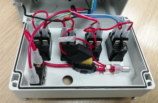
Introduction

Thank you for purchasing your new Sumo machine. We at Sumo pride ourselves in our ability
to produce compact, heavy duty and quality machinery. We hope you enjoy our products and
that it helps improve your productivity in every way. For any further enquiries about
additional products, optional extras or spares, please contact your local
dealership/representative, or alternatively contact us directly using the contact details given
on the cover page.

This Operators Manual is a comprehensive formulation of the directives and obligations
necessary to be undertaken before and after any operation is performed, including
maintenance and storage. It is important that each operator reads and understands this
manual completely before trying to use the associated machine. This will reduce the chance
of injury to both the user and persons around the machine, as well as reducing the likelihood
of machine misuse which could result in part failure and/or significantly reduce the service
life of the machine. Sumo will not accept liability for any injuries or damage caused from
negligence, use in extreme conditions, or failing to comply with the instructions within this
manual.

These machines have been designed to take Sumo manufactured spares; non-genuine
parts/accessories/modifications may damage the machine as they are untested and not
recommended for use with the Sumo machine. Sumo will not honour warranty claims if
deemed to be caused using non-genuine parts or accessories. Conversions of/ or
modifications to the machine may only be carried out after consultation with Sumo.

As well as reading the instructions of operation contained within this manual, a trained technician
or dealer should also instruct you on the correct and safe use of the machine and maintenance of
the machine to ensure a long service life.

Training by Sumo is required for the following operations; loading for truck transportation,
commissioning of new machines, advanced troubleshooting and repair. Any repair work to
structural components of the machine must be carried out by Sumo or a workshop approved
by Sumo, otherwise the warranty will be invalidated.

Please note, specifications, descriptions and illustrations in this manual are accurate, at the
time of publication but may be subject to change. If you notice any discrepancy and are in
need of clarification, please contact us using the details given previously.

                                                                                         2|Page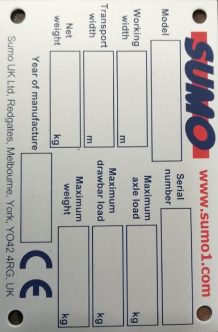
Contents
 1. Safety                                                 Page 5
             1.1   Qualification & Training                - Page 5
             1.2   General Safety                          - Page 6
             1.3   Personal Protective Equipment (PPE)     - Page 7
             1.4   Warning Symbols                         - Page 7

 2. Product Summary & Machine Identification               Page 10
             2.1   Summary Description                     - Page 10
             2.2   Intended Use                            - Page 11
             2.3   Machine Identification                  - Page 11
             2.4   Technical Data                          - Page 11

 3. Preparation & Set Up                                   Page 15
             3.1   Pre-Check & System Overview             - Page 15
             3.2   Hitching & Tractor Connection           - Page 15
                      3.2.1 Mounted Machines               - Page 17
                      3.2.2 Trailed Machines               - Page 17
             3.3   Electronics Connection & Testing        - Page 18
             3.4   Hydraulics Testing                      - Page 18
             3.5   Uncoupling of Tractor                   - Page 18

 4. Transportation                                         Page 19
             4.1   Transport Preparation & Positions       - Page 19
             4.2   Transport Guidelines & Route Planning   - Page 20
             4.3   Parking                                 - Page 20
                      4.3.1 Stands                         - Page 20
                      4.3.2 Handbrake                      - Page 22
                      4.3.3 Pneumatic Brakes               - Page 23
                      4.3.4 Hydraulic Brakes               - Page 23

 5. Operation & Adjustment                                 Page 24
             5.1   Operations                              - Page 24
                      5.1.1 Straights                      - Page 24
                      5.1.2 Turning                        - Page 24
                      5.1.3 Hydraulics                     - Page 25
             5.2   Adjustments                             - Page 25
                      5.2.1 Packer Depth                   - Page 25
                      5.2.2 Leg Depth                      - Page 26
                      5.2.3 Shear Pin                      - Page 26
                      5.2.4 Auto Reset Legs                - Page 26
                      5.2.5 Discs                          - Page 27
                      5.2.6 Paddles                        - Page 28
                      5.2.7 Scrapers                       - Page 29
                      5.2.8 Shim Holders                   - Page 29
                      5.2.9 Depth Wheel                    - Page 29
                      5.2.10 Soil Retention Disc           - Page 30
                      5.2.11 4-Way Control Box             - Page 30
             5.3   Parts Replacement                       - Page 30

                                                                       3|Page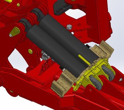
6. Maintenance & Storage Program                         Page 32
         6.1    Lubrication & Greasing                   - Page 32
         6.2    Cleaning                                 - Page 33
         6.3    Storage                                  - Page 33

7. Optional Extras/Attachments                           Page 34
         7.1    Point Variations                         - Page 34
         7.2    Packer Options                           - Page 34
         7.3    Sumo Seeder & Seeder Fitting Kit (SFK)   - Page 35
         7.4    Trailing Kit                             - Page 36
         7.5    Front Discs                              - Page 36
         7.6    Rear Drawbar                             - Page 36
         7.7    Air Brake                                - Page 36
         7.8    Wheel Eradicators                        - Page 37
         7.9    Following Harrow                         - Page 37
         7.10   Straight Leading Disc                    - Page 38
         7.11   Hydraulic Parking Stand                  - Page 38
         7.12   Gull Wings                               - Page 39
         7.13   Single Disc Opener’s (SDO’s)             - Page 39
         7.14   Homologation                             - Page 40

8. Troubleshooting                                       Page 41
         8.1    Mechanical Assemblies                    - Page 41
         8.2    Hydraulics                               - Page 41
         8.3    Electrical Faults                        - Page 41

9. External Documentation                                Page 42
         9.1    List of Machine Manuals & Parts Book     - Page 42
         9.2    Associated Legislation & Compliances     - Page 42

                                                                     4|Page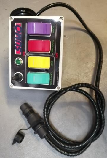
1. Safety
  The following warnings and safety instructions apply to all sections of these operating manual
  and should be read/considered in conjunction. The machine has been designed and
  manufactured to meet all the relevant safety regulations. These regulations along with the
  instructions provided within this manual are designed to help minimise the risk of injury to
  yourself and others around the machine at all times. Failure to comply with the safety
  obligations herein can result in any claims for failed machines/components, warranty, or
  damages being made void.

  Please read ALL these safety instructions prior to the use of the machine to prevent safety
  issues or potential machine damage through incorrect use.

  The designations “left”, “right”, “front” and “rear” refer to the direction of travel, as seen in the
  direction of travel, as the operator is sat in the driving seat looking forward.

 1.1   Qualification & Training

       Use of the machine by untrained operators can lead to injury or even death. To prevent
       accidents occurring ensure that operators have been trained by a Sumo dealer or
       technician. The following requirements must be met:

           -   Personnel must be of statutory minimum age in the country of operation.
           -   Ensure only reliable, authorised persons operate or work on the maintenance of
               the machine.
           -   Employ only trained or instructed staff; the individual responsibilities of the
               personnel concerning operation, setting up, maintenance and repair must be
               clearly established.
           -   Persons undergoing training or instruction or taking part in a general training
               course should not be allowed to work on or with the machine unless they are
               under the constant supervision of an experienced person.
           -   The person has read and understood these instructions in full.
           -   The person is fully competent/legally licensed in operating the machine towing
               the equipment.
           -   All Local traffic laws are understood and abided by.
           -   A person being instructed on the use of the machine must be done so under the
               instruction of a trained individual.

        It is the sole responsibility of the owner of the machine to ensure all requirements are
        met by any individual intended to use/maintain/repair/transport the machine,
        including official training by an authorised trainer, having read and understood this
        manual in full, their area of responsibility, and Local Laws, Legislation & Regulations
        Standards.

        Training by Sumo is required for the following operations; loading for truck
        transportation, commissioning of new machines, advanced troubleshooting and repair.

                                                                                           5|Page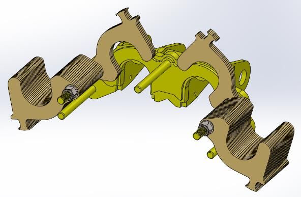
Any repair work to structural components of the machine must be carried out by a
workshop approved by Sumo, otherwise the warranty will be invalidated.

                                                                      6|Page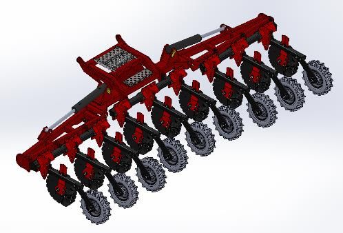
1.2   General Safety

      It is the responsibility of the owner/user to ensure a safe working environment, not only
      for themselves, but those around them. The following instructions are advised to help
      ensure this is made possible.

      Due to the nature of Sumo machines, the entire machine and surrounding area is
      classified as a Danger Zone, and the following instructions must be followed:

         -   Warning signs and other notices on the machine provide important information
             for safe operation. Observing and following them will serve your safety. Ensure
             they are clean, undamaged and clearly visible at all times.
         -   To avoid serious injury, ensure tractor keys are removed before making any
             adjustments or maintenance.
         -   With the drive still running/turned off, machine parts may fall, rotate or swing
             out. Ensure to stay clear of any risk area.
         -   Never allow anyone to stand, beside or behind the stationary machine, or whilst
             attached to a tractor, unless it is fully secured against rolling away by means of
             parking brake and/or wheel chocks. Even then all safety precautions herein must
             be followed.
         -   Before starting work, make yourself familiar with all the equipment and controls
             as well as their functions.
         -   The user should wear all necessary PPE as described in the PPE section of this
             manual.
         -   Adhere to all maintenance instructions given within this manual.
         -   Avoid any finger traps.
         -   Keep the machine and the bearings clean to avoid risk of fire.
         -   Maintain the upkeep of any electronics. Defective, incorrectly fastened electric
             lines, exposed wires can cause electric shocks.
         -   Remain vigilant around the machine at all times, hydraulically raised machine
             parts can lower slowly and unnoticed.
         -   It is expressly Forbidden for anyone to ride on our machines at any time.
         -   Never stand under the machine or lifted loads. Lower to the ground first.
         -   Machines should never be parked, folded or unfolded, or accessed in the
             presence of overhead power lines or pylons to ensure no flashover is possible.
             Special care should also be taken when manoeuvring nearby, folding or
             unfolding to ensure no contact is made.
         -   Instruct persons to leave the danger zone around the machine and tractor.
         -   Before working in the danger zone of the machine or between machine and
             tractor: Shut down the tractor! This also applies for short-term inspection work.
             Many accidents happen because of carelessness and running machines!
         -   Accidental operation of the hydraulic system can trigger dangerous movements
             of the machine.

                                                                                    7|Page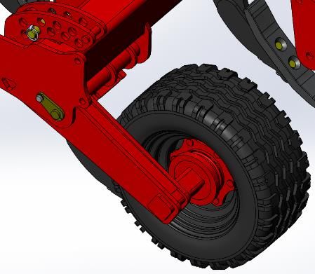
-   Failing to pay attention to the danger zone can result in severe or even fatal
              physical injuries.
          -   Check around the machine before moving off or starting up (Watch out for
              children or animals!). Make sure you have adequate all-round visibility.
          -   Always match your speed to the local conditions. Avoid any sudden acceleration
              or turning manoeuvres when driving uphill or downhill or when travelling across
              a slope.
          -   Consider the length, the wide overhang, the folded height and the sideways force
              acting on the machine when turning or negotiating curves.
          -   Ensure all transportation guidelines are followed within this manual.
          -   Ensure Sumo machines are only used for their intended use as outlined in this
              manual.

      Young persons are less able to react to danger and are unlikely to have enough
      experience to react to situations and therefore should be kept well clear of the operating
      zone of the machine. Children should Not be left in/on the tractor/machine even when
      the machine has been shut down as hydraulics can still be operated if they are a
      mechanical spool. The minimum age of children riding on agricultural equipment locally
      in the country of operation must be adhered to. Sumo does not permit Anyone to ride
      its machines at any point, trained or untrained.

1.3   Personal Protective Equipment (PPE)

      To protect the user and persons surrounding                       the   machine      during
      operation/maintenance suitable PPE must be worn:

          -   Tight fitting clothes or overalls, ensuring no loose clothing is able to get caught
              in the machine while it is in operation, this includes long hair, which should be
              tied up or placed in a hair net.
          -   Suitable footwear, steel toe capped shoes/boots, especially during the lowering,
              detachment or adjustment of any machine/feature.
          -   Eye protection such as safety glasses or goggles during general usage and
              especially when changing wearing components as these may be under pressure
              and can release suddenly, and when working with hydraulic components as the
              pressure may not have been released properly and could release suddenly.
          -   Jewellery such as rings, necklaces, bracelets and watches should not be worn
              while operating/maintaining this machine as it can get caught and cause further
              injury.
          -   Suitable hand protection, specifically during adjustment, maintenance, and when
              attaching the machine to a tractor as hydraulic oil can cause injury if it is under
              pressure as it can pierce the skin and cause serious health problems if it enters
              the blood stream.

      As a general rule, Sumo advise all PPE to be worn at all times, just to be safe.

                                                                                         8|Page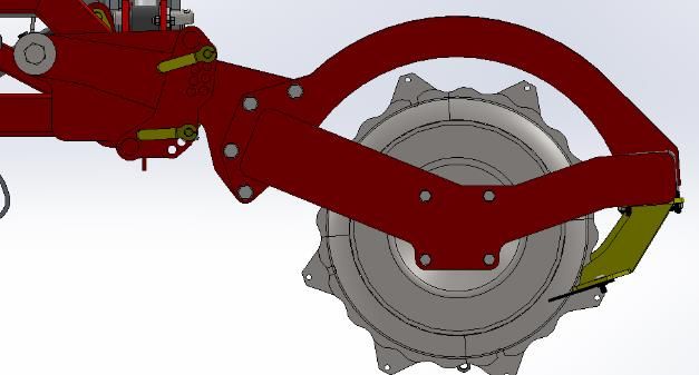
1.4   Warning Symbols

      Warning/Safety stickers have been positioned on the machine to warn of dangerous
      points and are an important part of the safety equipment of the machine. Missing safety
      stickers increase the risk of severe or even fatal physical injuries. It is crucial that all
      operators and spectators abide and understand them.

      Before any operation, and a standard maintenance regime, ensure all warning/sticks are
      clean, undamaged and clearly visible.

      The following is a general pictorial and description key for each warning/sticker typically
      used by Sumo. If there are any warning/stickers you are unsure of, or you think maybe
      be missing, either on the machine or in this manual, make sure to contact Sumo or a
      local dealership before taking any further action.

      Warning/Safety Labels:

                     Stop Engine!
                                                                       Risk of falling.

                     Consult Operation
                                                                       No riding on
                     Manual Before
                                                                       machines
                     Continuing.

                                                                        Warning!

                     Risk of crush.
                                                                        Ensure rear discs
                                                                        are in down and
                     Stay clear of                                      clear of tyres
                     unfolding and/or                                   position before
                     swinging elements                                  folding and
                                                                        unfolding
                                                                        (Applies to Disc
                                                                        Machines Only)

                               Never reach in to
                               working parts.
                               Risk of crush
                               injury.

                         Grease Daily.
                         Failure to do so may
                         diminish the life service of
                         the machine or cause
                         faults.

                                                                                          9|Page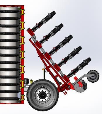
Closed top link only.
Do not use Open Top Link.

      Never reach in to
      working parts.
      Risk of crush
      injury.

      Shear Pin Machines Only!

      Advance new replacement shear pin
      through two extra positions on this
      leg

   Keep Fingers Clear!
   Change leg depth from underneath.

  Stay clear of machine while
  manoeuvring, stationary but
  unsupported, and/or working.

   Caution!
   Read manual carefully.

                                            10 | P a g e
Warning!
Ensure stands are raised and safety
link is removed before unfolding.
Failure to do so will result in damage
to the wings.
11 | P a g e2. Product Summary & Machine Identification
This section of the manual is designed to outline the basic machine range summary’s,
intend use outline, and machine variants/identification. This information is accurate, as
known, at the point of publication but is also subject to change at Sumo’s discretion.
For a more detailed descriptions, specifications & technical details - see www.sumo1.com,
or consult the correlating Machine Manual & Parts Book.
2.1 Summary Description
The following are brief summaries for each machine type, outlining the design concept
and intended use.
Trio - The Trio is a one pass seed bed preparation machine, designed to alleviate
sub-surface compaction and mix stubble and soil, leaving a level surface ready
for seeding.
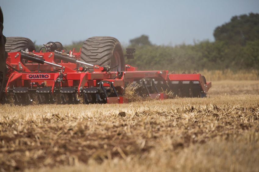
Quatro - The Quatro is a versatile, one pass, minimum tillage cultivator with four
elements that can be fine-tuned to adapt to a variety of conditions.
Vaxio - The Vaxio is a versatile high-speed cultivator which combines surface
cultivation and loosening to a depth with even levelling and consolidation in
one pass.
Multipress - The Multipress is a versatile machine designed for tilling, levelling and
pressing on a wide variety of conditions.
Mixidisk - The Mixidisk is a high-speed multipurpose cultivator designed for tilling,
levelling and incorporating large volumes of crop and residue.
LDS - The Low Disturbance Subsoiler (LDS) alleviates compaction with minimal
surface disturbance.
GLS - The Grassland Subsoiler (GLS) improves and revitalises compacted grassland
that is suffering from the effects of continual heavy machinery, livestock and
rainfall.
Subsoiler - The Subsoiler is a heavy-duty, robust machine which enables the
loosening and consolidation of compact soil conditions.
Rippa - The Rippa is a heavy-duty deep cultivation tool designed to rip up the land,
aiding aeration of the soil.
Strake - The Strake is a high-speed straw rake used for creating a stale seed bed. An
essential machine for effective use of minimum tilling and direct drilling.
12 | P a g eFront Multipacka - The Front Multipacka is a heavy-duty machine that breaks up the
soil and creates an even consolidation, as well as having the
benefit of acting like a front weight.
13 | P a g e2.2 Intended Use
Based off the Summary Descriptions previous, Sumo machines are intended to be used
for normal soil cultivation in agricultural practices associated with those requirements
only.
Any use outside of the intended use/summary description of the machine can lead to
injury to persons operating or within the area of the machine and can also lead to the
warranty being invalidating. Sumo accepts no liability for the actions or use of any
operative not employed by Sumo UK Ltd.
Any faults with the machine should be rectified prior to use. Faults can cause safety
issues and can also cause the machine to work in an unsatisfactory manner.
Only qualified persons, as outlined in the Qualifications and Training section of the
manual, may operate this machine.
2.3 Machine Identification
The following is a blank picture of the serial plate attached to the front of every
machine:
To identify your machine, find your serial plate and cross-reference the details with
the Technical Data that follows.
Note: It is important when talking to a Sumo representative that you provide the year
of manufacture in order to ensure clarity of the machine being discussed, as different
years may have slight or major design variations.
2.4 Technical Data
The following collection of tables denote the different machines available in each
range of Sumo products, and include the basic collection of technical data applicable
to those machines. For a more detailed technical data, see the correlating Machine
Manual & Parts Book.
14 | P a g eNote: All dimensions hereafter are approximate and in metric. Length, width and
height dimensions refer specifically to the machine whilst in its required transport
positions, see Machine Manual & Part Books. All weights are based on standard
machines without any additions, modifications or loads. All machines are subject to
fabrication and assembly tolerances and could vary slightly from values given. Lengths
and Height have been omitted from all Mounted machines as the value is entirely
dependent on the connected tractor.
Machine Type Key:
Mounted = Machine mounted directly to a Tractor.
Rigid = Trailed Machine that does not fold.
Folding = Trailed/Mounted Machine that hydraulically folds.
Trio Range
Code Machine Working Length Width Height Weight
Type Width (m) (m) (m) (m) (kg)
TR2.5SP Mounted 2.4 - 2.55 - 2468
TR2.5AR Mounted 2.4 - 2.55 - 2515
TR3SP Mounted 2.9 - 3 - 2795
TR3AR Mounted 2.9 - 3 - 2855
TR3.5AR Mounted 3.4 - 3.5 - 3070
TTR3AR Rigid 3 7.6 3.25 2.2 4220
TTR3.5AR Rigid 3.5 7.6 3.75 2.2 4706
TRF4.5AR Folding 4.5 8 2.9 2.64 8631
TRF5.5AR Folding 5.5 8 2.9 3.14 9101
TRF6.5AR Folding 6.5 8 2.9 3.64 10025
Quatro Range
Code Machine Working Length Width Height Weight
Type Width (m) (m) (m) (m) (kg)
Q3 Rigid 3 9.05 3.25 2.17 5930
Q4 Folding 4 10.4 3 3.56 10210
Q5 Folding 5 10.4 3 3.94 11965
Q6 Folding 6 10.4 3 3.96 12958
Vaxio Range
Code Machine Working Length Width Height Weight
Type Width (m) (m) (m) (m) (kg)
V4 Folding 4 8.76 3 3.27 7380
V5 Folding 5 8.76 3 3.77 8352
V6 Folding 6 8.76 3 3.94 9224
15 | P a g eMultipress Range
Code Machine Working Length Width Height Weight
Type Width (m) (m) (m) (m) (kg)
MUL3 Mounted 3 - 3 - 2440
MUL5 Folding 5 7.91 3 3.35 6950
MUL6 Folding 6 7.91 3 3.59 7770
Mixidisc Range
Code Machine Working Length Width Height Weight
Type Width (m) (m) (m) (m) (kg)
MIX3 Mounted 3 - 3 - 2010
MIX4 Folding 4 - 2.8 - 3220
TMIX5 Folding 5 7.7 3 3.36 6860
TMIX6 Folding 6 7.7 3 3.86 7985
TMIX7 Folding 7 7.7 3 4 9005
LDS Range
Code Machine Working Length Width Height Weight
Type Width (m) (m) (m) (m) (kg)
LDS3FAR Mounted 3 - 3.1 - 2170
LDS3RAR Mounted 3 - 3.1 - 2450
LDS3MAR Mounted 3 - 3.1 - 2450
LDS4FAR Folding 4 - 2.9 - 3085
LDS4RAR Folding 4 - 2.9 - 3315
LDS4MAR Folding 4 - 2.9 - 3315
LDS5FAR Folding 5 - 2.9 - 3645
LDS5RAR Folding 5 - 2.9 - 3990
LDS5MAR Folding 5 - 2.9 - 3990
LDS5TM Folding 5 7.47 3 2.9 10300
LDS6TM Folding 6 7.47 3 3.3 11150
Note: Based on the packer bought: FAR = Flat, RAR = Rings, MAR = Multipacka. TM =
Trailed Multipacka. See Packer section of this manual for more details.
GLS Range
Code Machine Working Length Width Height Weight
Type Width (m) (m) (m) (m) (kg)
GLS3AR Mounted 2.3 - 2.5 - 1490
GLS4AR Folding 2.3 - 2.5 - 1625
GLS5AR Folding 2.3 - 2.9 - 1875
Subsoiler Range
Code Machine Working Length Width Height Weight
Type Width (m) (m) (m) (m) (kg)
S3SP Mounted 2.7 - 3 - 2200
S3AR Mounted 2.7 - 3 - 2480
16 | P a g eS4SP Folding 2.8 - 3 - 2360
S4AR Folding 2.8 - 3 - 2575
S5SP Folding 3.4 - 3.6 - 3000
S5AR Folding 3.4 - 3.6 - 3250
SF7SP Folding 4.7 8.7 2.9 2.9 7204
SF7AR Folding 4.7 8.7 2.9 2.9 8014
SF9SP Folding 5.9 9.1 2.9 3.3 8248
SF9AR Folding 5.9 9.1 2.9 3.3 8818
Note: SP = Shear Pin, AR = Auto Reset. See adjustments section of this manual for
more details.
Rippa Range
Code Machine Working Length Width Height Weight
Type Width (m) (m) (m) (m) (kg)
R3 Mounted 3 - 3 - 1425
R4F Folding 4 - 3 - 2820
R6F Folding 6 - 3 - 3240
Strake Range
Code Machine Working Length Width Height Weight
Type Width (m) (m) (m) (m) (kg)
S6 Folding 6.1 - 2.8 - 2435
S8 Folding 8.1 - 2.8 - 3100
S12 Folding 12.1 3 7950
17 | P a g e3. Preparation & Set Up
The following statements apply to the full range of Sumo cultivators. For an overview of
your specific machine, see associated Machine Manual and Parts Book in conjunction with
these instructions.
3.1 Pre-Check & System Overview
Before performing any other action on a Sumo machine, always check the following:
- Check the machine for worn or loose parts, mechanical and structural integrity,
hydraulic leaks, exposed or corroded wires, warning label cleanliness and clarity.
- Maintenance programme carried out in line with schedule.
Faulty equipment can lead to damage to the machine or injury to persons. Always be
diligent and ensure the machine is in perfect condition before use.
3.2 Hitching & Tractor Connection
Faulty hitching up of the machine to the tractor causes dangers, which could result in
severe accidents. Hitching and unhitching of the machine should only take place on a
secure and level surface with chocks placed under the wheels of trailed machines to
prevent the machine from rolling away.
General Safety
Familiarise yourself with the machine and all safety guidelines/regulations given in this
manual, industrial standards, and safe work practices, before attempting any hitching
of Sumo Machines.
Never allow anyone to stand between the tractor and the Sumo machine whilst the
tractor is manoeuvring into position. Only once the tractor is in position and secured
against rolling away, by means of parking brake and/or wheel chocks, can the
operator/third party secure the machine to the tractor.
Ensure the wings are either in the fully up ‘transport’ position or fully down in the “work”
position before uncoupling from the tractor. The machine should always remain secured
to the tractor when the wings are anywhere between fully up and fully down.
Always ensure tractor hydraulics are depressurised before attempting hydraulic
connection.
Types of Hitch
Sumo machines come with a variety of hitch types; fixed, adjustable, bolted. The tractor’s
hitch must be suited/adapted to match the machines requirements.
Fixed hitches generally refer to either a fixed position drawbar for trailed machines, or
three-point linkage for mounted machines.
18 | P a g eAdjustable hitches are single point connections that allow the hitch height to be adjusted
to suit tractor requirements.
Bolted hitches generally refer to an externally supplied, pre-rated and approved hitches
which can be purchased separately or selected during the consultancy period (Note:
These may not be available on all machines). For more information contact your local
dealership or Sumo representative directly.
Fixed (1) Fixed (3) Adjustable Bolted
Standard Hydraulic Connections – Colour Code
Sumo’s colour coding is done through a
sequence of cable ties attached to the
individual hydraulic hoses, as seen in
this picture. Before connection, ensure
all connections are cleaned to reduce
the risk of contamination.
One cable tie = Return
Two cable ties = Pressure
Yellow = Drawbar
Orange = Fan – Front Hopper Only
Folding Axle
Blue = Legs
Pink = Rear Discs
Red = Wings
Purple = Auxiliary
Green = Front Discs
Paddles
Air Brake Connections
The air brake hoses are colour coded as follows:
Yellow = Service Line
Red = Emergency Line
19 | P a g eHydraulic Brake Connections
Hydraulic Brake hose connections are not colour coded, however the connection
socket is shaped so that it cannot be mistaken or interchanged with any other
connection. Ensure hose is depressurised before coupling/uncoupling.
3.2.1 Mounted Machines
Due to the physical nature and weight distribution of some Sumo machines a
category three enclosed ball top link is highly recommended. Due to the
exaggerated loads experienced during normal working conditions, the top link
pin is considered as a consumable part and should be checked for wear on a
regular basis.
When hitching the Sumo machines three-point linkage to the tractor, ensure the
linkage arms are correctly angled so that the lower arm is horizontal and top
arm linkage is diagonally aligned with the tractor’s front axle. This will ensure a
strong, stable weight distribution and connection. Top & Bottom linkage arms
should never be parallel. Having them parallel will reduce the tractors drive
wheel grip and may cause damage to both the tractor and the linkages.
Steps:
• Attach lower linkage points first, then attach the top linkage, ensuring a
permanent and secure fix.
• Turn tractor off, float hydraulic systems, then safely connect hydraulic &
electric connections.
• Lift machine just enough to clear the ground of any parking
feature/working instruments.
• Remove parking features/position them in the transport/working
positions.
• Perform all necessary tests as outline within this manual.
• Turn tractor back on.
3.2.2 Trailed Machines
Trailed machines come in two variants, rigid & hydraulic drawbar, depending on
the design. Both follow the same hitching process, although hydraulic drawbars
can be positioned to better suit the tractor hitch point, if necessary.
20 | P a g eSteps:
• Slowly back tractor up to machine.
• Release pick up hitch in a low position, extend outwards if required.
• Reverse carefully up to hitch and locate hitch onto machine towing eye.
• Retract hitch if it has been extended.
• Raise hitch until locking pin is secured.
• Lower three-point linkage to release upward pressure on pick up hitch.
• Turn tractor off, float hydraulic systems, then safely connect hydraulic &
electric connections.
• Lift machine just enough to clear the ground of any parking
feature/working instruments.
• Remove parking features/position them in the transport/working
positions.
• Perform all necessary tests as outline within this manual.
• Turn tractor back on.
3.3 Electronics Connection & Testing
Plug all electronic equipment in. Walk around the machine and ensure all lights are
functional. Visually inspect wiring looms for any exposed wires, breakages or damage.
If the system shows any sign of issue, see the troubleshooting section of this manual.
If you have any additional Sumo electronic equipment, see the Optional
Extras/Attachments section in this manual.
3.4 Hydraulics Testing
Check general hoses condition, abrasion, kinks etc. Visually inspect for leaks or
damaged connections. Do not touch with hands or get close enough to inhale any
vapours. Check cylinder condition and cleanliness. Run each system individually i.e.
wings up and down, drawbar up and down. If the system shows any sign of issue, see
the troubleshooting section of this manual.
3.5 Uncoupling Of Tractor
Never uncouple on an uneven or unstable surface. Ensure both the tractor and the
Sumo machines are on level, solid ground and put them in a secured configuration,
by use of handbrakes, chocks and any other movement prevention systems available.
Tractor must be fully immobilized with the key removed from the ignition. Obey all
other relevant safety practices outlined within this manual, including but not exclusive
to, the machine in general, hydraulics and electrics, and environmental awareness.
21 | P a g eLocate machine on the provided stands, or parking elements (see parking section of
this manual), Depressurise all hydraulics before disconnection, and ensure all electrics
are detached and safely tied back. Only once the machine is fully stabilised and clear
of the tractor linkage should the tractor be driven slowly away, remaining vigilant to
not drag or knock the machine.
22 | P a g e4. Transportation
When the machine is being transported on the road the local road regulations must be
adhered to, regulations such as transport length, width and height, escort vehicles &
loading.
Due to the length and design of many Sumo machines, the transportation wheels are often
to the rearmost of the machine meaning it will cut corners. Care must be taken to ensure
a wide swing and reasonable turning arc is maintained to avoid any fouling of other
vehicles or road markings/obstacles.
Note: Training by Sumo is required for loading any machine for truck transportation.
General Road Safety
- Always consult and abide by your local highway code.
- Observe the respective regulations when using public roads and ensure the machine is
in the legal transport position before proceeding.
- Check around the machine before moving off or starting up (Watch out for children or
animals!). Make sure you have adequate all-round visibility.
- Always match your speed to the local conditions. Avoid any sudden acceleration or
turning manoeuvres when driving uphill or downhill or when travelling across a slope.
- Consider the length, the wide overhang, the folded height and the sideways force acting
on the machine when turning or negotiating curves.
- Ensure all electronics are connected and fully functional.
- Ensure all markings and signage are clean and fully visible.
- Empty all machines of grain and/or fertiliser, and any additional loads before
commencement of journey to minimise burden weight.
- Clean shoes of any debris or mud to ensure clean, non-slip contact with pedals.
- Removed any gloves that may have grease on them, and clean hands to ensure a good
grip.
- Never operate hydraulic systems whilst the machine is on public roads. All hydraulics
should be disconnected and strapped down to avoid any accidental unfolding.
- Ensure all parking features are fully retracted and in the correct transport position.
- Ensure all hitch points are firmly secured and pins are prevented from being
unsecured.
- Check no parts are loose, damaged or broken, especially after being in work.
- Check for hydraulic leaks or damage that might cause them to fail. Do not take on the
road if there are any signs of issue.
- Check tyre pressure and wheel nut torque are adequate.
- Mounted machines: Ensure all legs are well clear of the ground.
- Ensure dog bone/wing latch is firmly applied.
4.1 Transport Preparation & Positions
23 | P a g eWhen transporting the machine on the highway it MUST be folded into the correct
transportation position in order to maintain the values given in the Technical Data
section of this manual, see corresponding Machine Manual & Parts Book for
Transportation Positions. Any machines failing to be in these positions whilst being
driven on the road will likely exceed your local road legislation and regulations, and
run risk of causing potentially fatal damage to other road users. It is the sole
responsibility of the operator to ensure they comply with all local road laws and Sumo
accepts no liability for negligence or carelessness.
4.2 Transport Guidelines & Route Planning
The route planned should also be considered to ensure that the machine will not incur
any difficult or extreme manoeuvres. The following is a list of basic guidelines design
to encourage safe journeys.
- Avoid low bridges or over passes. Sumo machine heights may vary, especially
when mounted directly to tractors. Care must be taken to ensure adequate
clearance.
- Avoid narrow gaps. Sumo machine widths may vary. Ensure wings are folded
fully, and ensure adequate clearance from any obstacle.
- Avoid weight restricted roads and ensure Sumo machines are not over-burdened
with any additional weights, such as mass mud collection, stored grain or
fertiliser.
- Avoid any steep inclines or drastic turns that may cause the tractor and/or
machine to roll back or tip over.
4.3 Parking
The following Parking options represent the generic options available, but actual
features are dependent upon machine type and spec purchased. Consult Machine
Manual & Parts Book for more details.
Always check Brakes daily before use to determine if the braking is fully functional.
Any adjustments or modifications to the braking system should be carried out by or
under the instruction/supervision of Sumo UK.
4.3.1 Stands
Parking stands come in three primary models, Slide Out (Primarily Mounted
Machines where the depth of machine features is adjustable), Fixed (Primarily
Trailed Machines), and Adjustable Jack.
Note: Always try to locate the machine on a flat, rigid surface to avoid additional
strain, slip or sinking of the stand. This action should only be performed when
the full weight of the machine is supported by a tractor. Once stand is
positioned, slowly lower machine back down until it is supported, ensuring to
keep fingers well clear of any finger traps. Some stands may be heavy so be
careful weight is not burdensome before trying to lift or lower it.
24 | P a g eFixed Stands
Fixed Stands generally consist of a welded bracket, a bolted joint and a pin,
offering two positions: In Work and Retracted. Simply remove pin, rotate the
bracket until in retracted or in work position and re-insert pin. Pins must always
be secured with an additional lynch pin. Never lift stands from the front or back;
always position them from the side so the stand pivots to the left or right of you.
Example:
Pin Stand
Slide Out Stands
Slide out stands are primarily used on machines with legs or other features that
have a variable depth/seating position. Slide out stands generally consists of a
sliding foot which can be pinned in multiple positions. To avoid damage to either
the machine or yourself, ensure stand is fully supported before removing the
pin, be careful not to allow it to slip or plummet suddenly, and pin once it is
situated as desired before letting go. Always ensure to keep feet and other body
parts away from the drop zone to ensure they are not crushed.
Example:
Pin
Stand
25 | P a g eAdjustable Jack Stands:
Adjustable jack stands generally consist of winding or lever systems allowing for
a much slower and measured movement, whilst also providing greater support,
or assistance with hitching/unhitching. To position an adjustable jack stand,
support stand with one hand and pinch the two clasp levers together with your
other hand until clear of holes, then lower slowly pivot and lower the unit down
until in next set of holes. Be careful these stands can be heavy. To determine
height, apply reasonable pressure to the movement mechanism until desirably
situated. Try not to jack the machine up any higher than is absolutely necessary
as this might have a destabilising effect.
To release pressure on lever systems, locate the pressure relief tap and open
slowly ensuring nothing is above you or about to descend.
Examples:
Pump
Clasp Pin
Clasp
Winding Handle
Stand
4.3.2 Handbrakes
Handbrakes are tailored to match each machines construction, but generally
operated from a single crank lever or winding handle, usually positioned at the
front or rear of the machine. Before operating the handbrake ensure the
machine is fully supported by the Tractors handbrake. Fully apply handbrake by
pivoting/turning the lever in the required direction and ensure machine hold.
Before unhitching the tractor, ensure any stands are down and positioned
suitably. On winding handbrakes make sure to put securing cable to the handle
to ensure handbrake is not activated during travelling.
Examples:
26 | P a g eCrank Lever
Release
Winding Handle
Catch
4.3.3 Pneumatic Brakes
Pneumatic brakes generally consist of two brake cylinders (one per wheel), a
pressurised air tank, a set of configured brake levers (Both usually located at
the rear of the machine closest the axle/wheels), and an REV (Typically located
near the front of the machine). For connection details, see Hitching and tractor
connections section of this manual.
Example System:
Relay Emergency Valve (REV)
Tractor Pressurized
Connection Air Tank
s
Brake Cylinder
Our Homologated Pneumatic brake systems also include a Park/Shunt Valve
normally located at the front of the machine for temporary release of machine
brakes for shunting, if no tractor is available/connected. Press once only to
release brakes. Make certain to have a clear environment before release and
keep well clear of machine just incase it slides/moves unexpectedly. Never use
when machine is on an incline. Note: Brakes will lock if Park/Shunt Valve is
pressed twice.
Example System:
Additional Park/Shunt Valve
27 | P a g e4.3.4 Hydraulic Brakes
Hydraulic brakes generally consist of two hydraulic cylinders attached directly
to the axle brake levers, typically located at the rear of the machine/mid-
machine axle. For connection details, see Hitching and tractor connections
section of this manual.
Example:
28 | P a g e5. Operation & Adjustment
Before using any Sumo machine, you must ensure you are qualified and trained to use the
machine in the safest possible manner. Familiarise yourself with both the machine and this
manual and follow its instructions. Sumo will accept no liability for any persons
trained/untrained using the machine inappropriately.
The material within this section is correct, as known at the time of publication, but may be
subject to change. If in doubt, ask your local dealership/Sumo representative.
5.1 Operations
Before Start
Ensure machine is correctly hitched as described in the Hitching section of this manual,
and ensure all securing mechanisms such as dog bones and/or wing locks are fully
detached/disengaged.
5.1.1 Straights
Lower working implements into the ground and accelerate slowly to ensure the
machine does not endure any immediate jolts of pressure. This will help extend
the life of the product and reduce any damage/wear to wearing parts.
Adjust hydraulic systems gradually and do not overburden the system with
constant heavy/excessive pressure. This may damage the system and
instruments. Some machine elements such as Tines are designed to be flexible
and absorb moderate amounts of strain, but excessive/ prolonged amounts
may cause them to snap, so always be gentle but assertive with the machinery.
Advisable speed for any Sumo cultivator is 5 mph/8 km.
5.1.2 Turning
Depending on the machine purchased, some Sumo machines can have large
turning circles. Ensure there is enough of a berth before initiating any turn.
Raise all implements fully out of the ground. Move slowly so the weight of the
machine does not shunt drastically over to one side and topple the tractor.
Avoid turning on any slopes or unstable ground.
When turning on headlands the machine should be lifted clear of the ground
and can be run on just the packer to prevent excessive compaction of headlands
rather than running on the wheels.
29 | P a g e5.1.3 Hydraulics
Folding/Unfolding
Always ensure a safe working environment as described within this manual when
folding/unfolding wings. Perform movements slow and safely paying special
attention to weight distribution, equality of descent, machine balance & stability,
environmental influences and neighbouring features/obstacles.
Drawbars should always be fully raised before the folding in of wings to ensure
adequate clearance from the ground to packer and other working instruments.
For more info, see machine manual & parts books for transportation positions.
Manual Change-Over Valves (MCOV)
Sumo use MCOV’s to isolate different hydraulic
systems from one another. Depending on the
system required, simply pivot the lever to the
desire direction. Always operate hydraulic
systems slowly to ensure the correct system
has been selected.
Accumulators
Sumo hydraulic systems use high pressure accumulators, which can present a
danger if tampered with or misused. This includes drilling, welding or any other
process that could compromise the safety of the accumulator. It is expressly
forbidden for an operator, or any third party to dismantle or adjust the
accumulator in any way. Doing so will invalidate any existing warranty. If the
accumulator fails it should be changed under the supervision/instruction of Sumo
UK.
5.2 Adjustments
Always ensure you wear the correct PPE as described previously, before attempting to
make any of the following adjustments, and watch out for any finger traps/potential
crushing.
5.2.1 Packer Depth
The machine will operate at its optimum and create maximum lift and cultivation
effect when the machine is set up so the wing frame/s runs parallel to the ground.
This is achieved by setting the machine working depth via the pin adjustment on
the packer. To do this the machine must be lifted completely clear of the ground
using the drawbar. The packer will then be sat up against the shallowest depth
pin and the desired depth setting can be set. For dual pin packers, lower packer
onto the deepest pin, then reposition the upper pin just above pack to lock it in
position.
30 | P a g eThis will set the working depth for any related elements. The machine should then
be levelled/limited through the use of the cylinder shim holder, see Shim holders’
section. For trailed machines, the retractable wheel axle can now be retracted.
5.2.2 Leg Depth
It is advised that the soil is assessed prior to working to determine the level of
compaction within the soil profile and the depth this compaction is at. The legs
should then be adjusted to work just below this level in the soil by removing the
handled pin holding the leg in place in the cast socket and moving the leg up or
down as required.
The leg should always be moved up and down by
holding onto the bottom of the leg where the point is as
opposed to the top or through the holes that may be
exposed through the top of the cast socket as this can
lead to fingers getting trapped or seriously injured.
Note; some leg profiles are quite heavy due to the
nature of their use, so ensure good posture before
trying to handle alone.
Support here
31 | P a g e5.2.3 Shear Pin (SP)
Shear pins only need adjusting once the shear pin has sheared
off. Simply remove the retention clip, correct the angle of the
Retention leg and advance the shear pin through legs oblong hole to the
Clip next stage, re-insert retention clip.
Always check to ensure the retention
bolts acting as the pivot and stopper,
are in good condition and do not
show signs of wear. Continued
pressure /movement, after the shear
pin has sheared can cause damage.
5.2.4 Auto Reset Legs (AR)
To adjust the AR, raise the machine so the legs are clear of the ground.
To adjust the pressure, release the lock ring and rotate the knob in the desired
direction (Clockwise to Increase pressure, Anti-Clockwise to Reduce pressure).
Secure lock ring once completed.
Flow Control
Leave wide Open
Pressure Adjustment
Knob
Lift and lower the legs to introduce the new pressure setting. Keep pumping
down for 5 seconds after last leg stops moving. Observe the new pressure
displayed on the gauge (Range 80 – 150 bar). It can be adjusted up to a
maximum of 120 bar, exceeding this pressure may result in serious damage to
the machine. The higher the pressure in the system, the greater the resistance
against the legs tripping, but increasing the risk of damage to the machine due
to underground obstacles.
32 | P a g eEven though the pressure is locked in the circuit, this system does remain active in
that the legs can be raised up out of work. The tractor hydraulics should be
returned to float to relieve any back pressure before commencing work at the new
pressure
Note: It is advised that on a machine fitted with auto reset legs the double acting
feature is used in road transport to retract the legs and reduce the overall width
of the machine on the road and move the sharp points to well within the
vehicle’s width.
5.2.5 Discs
Disc are usual set in one of three ways: a tilt mechanism, hinge racks operated
by hydraulic cylinders, and by setting packer depth which automatically sets the
disc depth.
Tilt mechanisms are most commonly used on our Leading
Disc. Simply remove the pin/bolt, tilt to desired angle and
reinsert pin/bolt.
Hinged disc arrangements operate
simply from a sequence of hydraulic
cylinders. To lower or raise, simply
adjust the hydraulic pressure.
33 | P a g e5.2.6 Paddles
Paddle arrangements
operate using a simply tilt
mechanism linked to a
sequence of hydraulic
cylinders. To lower or raise,
simply adjust the hydraulic
pressure, see hydraulic
connections section of this
manual.
5.2.7 Scrapers
Scrapers come in an assortment of brackets and
profiles, depending on the packer type & frame
requirements, but all function in the same way.
To adjust the wearing pads distance from the
packer, simply loosen the bolts and slide the pad
forwards. The dual slot design also allows for the
pad to slide left or right to better centralise upon
the packer and avoid any unwanted side
wearing. It is advised that these pads are
inspected before and after every use.
5.2.8 Shim Holders
Shim holders come in two variants to suit single and double-cylinder systems.
To adjust, simply retract cylinder until clear of shims, pivot shim quantity in/out.
Do not stand near shim holders when cylinders are making contact.
For double cylinder systems, try to ensure both cylinders contact the shim
holder on a symmetrical, level platform of shims. Failure to do so may cause
damage to the shim holder/cylinders.
34 | P a g e5.2.9 Depth Wheel
Depth wheels come in a variety of different forms, but generally work either on
a simple pin or top link system.
For Pin Systems, simply remove the pin, raise
and lower the depth wheel to the desire
specification and reinsert the pin. Ensure any
lynch pins are in place so that the pin cannot
slip out during use.
Pin
Note: This is only an example system intended
for indication purposes only, and may not
exactly visually match your machine.
For Top Link Systems, simply loosen locking
plate on both sides of main body, wind main
body until desired distance is achieved, then
tighten locking plates back onto main body.
Top Link
5.2.10 Soil Retention Disc
Soil retention discs can be adjusted by relocating the
bearing bracket into one of the other pre-set hole
positions via two bolts. It is advised that the Nylock nuts
are replaced after loosening.
5.2.11 4-Way Control Box
The 4-Way Control Box is an easy system with 4 control settings. Simply flip the
black toggle up or down to turn the box on or off, then press the colour button
that represents the system you wish to use. Note; This system is only available
on select machines.
35 | P a g eGreen = Front Gang Yellow = Legs
Red = Rear Gang Purple = Wings
If green light is not on, check Box is plugged in correctly, turn it on and off again,
if still no green light, check 20A fuse, replace if faulty, if not faulty, replace LED.
5.3 Parts Replacement
For a list of the replaceable parts for your machine, see the relative Machine Manual
& Parts Book. For any parts not covered in these documents, contact Sumo directly,
as they may be relevant to a set period of manufacture. Sumo do not sanction the use
of any products/parts not produced and managed by Sumo. Using external products
will invalidate your warranty. When ordering replacement parts please have your
serial number, part numbers and quantities at hand.
When tightening points to legged machines, do NOT use an air rachets, or over tighten
with spanners. Excessive tightening will result in points cracking. Use standard ISO
torque values for the fasteners suggested by the Parts Books, unless otherwise
specified.
36 | P a g e6. Maintenance & Storage Program
In general Sumo advise that you should visually check over the machine before each
operation and transport to ensure there are no visible defects, loose parts or risk to either
the operator or the public. Maintaining a thorough regimented maintenance schedule will
help to prolong the life of your machine.
Wherever possible stand on flat, clear platforms and NEVER on rotating, breakable, or
adjustable elements such as the packer, points, disc etc. Avoid all cables and hoses. Be
mindful of your footing and an environmental element that may cause additional
movement. As the machines are mostly painted surfaces can be slippery. All wings and
foldable elements must be full folded out before approaching the machine. NEVER stand
on a folded machine, or under its foldable features. NEVER stand on the machine when it
is connected to an active tractor. Follow all advised parking guidance given within this
manual.
Wheel studs on trailed machines should be checked for tightness after the first 10 hours
of operation and then again at regular weekly intervals. Tyre pressures should also be
checked at regular intervals, more so during continued use. For torque values and tyre
pressures, see the relative Machine Manual & Parts Book.
The condition of the packer scrapers should also be observed routinely in order to prevent
soil building up on the packer. Ensure the scrapers are adjusted up tight, but not touching
the packer though as this will increase rolling resistance and cause premature wear of the
packer and scrapers.
Some Sumo parts are intended to be wearable due to the nature of their design and use.
For best results, check routinely and replace as required. This will help prevent
loss/destruction of implements during work.
Check and re-tighten all fasteners every 24 hours. Tighten to standard ISO values, unless
otherwise stated. If removed, all Nylock and/or Aero-tight nuts must be replaced, otherwise
they lose their effectiveness.
6.1 Lubrication & Greasing
Lubrication and greases can be harmful to both the user and the environment. Avoid
contact with skin/eyes. Make sure to clean up any unwanted spillage, and always wear
the correct PPE for these activities. Sumo advise using sustainable, biodegradable oils,
unless otherwise stated. Avoid mixing substances, otherwise you risk causing a
chemical reaction. Do not use pneumatic grease guns as the pressure can cause
damage to bearings. Always wash your hands thoroughly and other contacted areas
immediately after contact.
Hydraulic Cylinders Inc Auto-Reset - Grease points requiring one pump every 50
hours are located on all rams, wing hinge bushes, axle hinge bushes, drawbar hinge
bushes front and back on both top and bottom elements. Exposed chrome ram rods
should also be greased weekly to prevent these valuable parts from rusting and
causing costly oil leaks.
37 | P a g ePacker Bearings - The packer bearings should be greased with one pump of grease,
once a week and after the machine has been washed off to force out any water that
may have impregnated the bearing .
Disc Bearings - The disc bearings should be greased until old grease is forced out once
a week when in normal use and after washing the machine off to expel any water in
the bearing.
6.2 Cleaning
High pressure washers can be used to clean Sumo machines, however for elements
such as bearings which are greased and have oil seals, try to avoid direct contact. This
may cause damage.
Sumo machines also have a variety of electrical equipment and cables running across
the machine. To avoid electrocution do not touch the machines whilst cleaning it, and
observe/repair any damaged electrical circuits.
For best results, clean the machine regularly and remove any build-up of dirt/mud
which might solidify and later cause bungs. A clean machine is a safe machine,
exposed to less pressure during working and transport, and will therefore serve you
better and longer.
6.3 Storage
It is generally advised to store Sumo machines in their folded positions to minimise
the exposure of unpainted rams, and lessen the impact on tools/wearable
components. Follow all parking guidance given within this manual. Wherever possible,
try to find a sheltered environment. If not possible cover with tarpaulin. This will better
protect the machine and slow the degradation of paint and materials, as well as
prolonging the effectiveness of greased areas.
When machines are to be parked up for the winter period, correct storage techniques
are an important part of protecting the machine to ensuring a hassle-free season.
When the machine has finished work it should be cleaned down and washed off to
remove all traces of soil. Following washing off, all lubrication and greasing should be
performed until old substances are forced out. To avoid delays next season, check
machines for worn parts and get them replaced asap.
38 | P a g e7. Optional Extras/Attachments
A variety of machines come with the options for multiple extras or attachments. For a list
of available options, please consult your Sumo catalogue, contact your local dealership or
Sumo directly, or search online – www.sumo1.com.
The following is a general overview of the Standard available options, there intended use,
and any special safety measures associated with that part/assembly. Consult your Sumo
representative before requesting any replacement parts/additional purchases, as some
designs may not be compatible with your machine, and are also subject to change. For a
more detailed outline, consult your Machine Manual & Parts Book.
7.1 Point Variations
Sumo machines come with multiple point options for a variety of different
circumstances, with or without tungsten tips. Note: Depending on machine age, some
points require a new/old leg be purchased.
Combi
Hybrid
Low
Disturbance Concord
Low Disturbance – Intended to be used for minimal disturbance of soil.
Concord – Intended to be used for some surface disturbance and provides some
elements of mixing trash and surface residue.
Combi – Intended to be used for highest surface disturbance.
Hybrid – Intended to be used for highest surface disturbance.
GLS Points are also available for multiple machines and are design for a less intensive
disturbance. Contact your local dealership/Sumo directly for more details.
7.2 Packer Options
Sumo machines offer a variety of packer options, depending on machine type, that
can be used for a variety of applications. Depending on the machine, packer options
either come as single drum assemblies to be bolted directly into existing packer
frames, or with fully fabricated frames designed to maximise their potential.
39 | P a g eMultipacka Diamond Tyre Flat
Sharp Channel Roller
Multipacka – Intended to provide and even consolidation of soil.
Diamond – Intended for maximum consolidation to depth whilst leaving a weather-
proof finish.
Tyre – Intended to provide a concentrated consolidation across the full width of the
machine
Flat – Intended to provide an aerated, consolidated level finish.
Sharp – Is most suited to heavy soils. Intended to slice and crack clods.
Channel – Is most suited to shallow cultivation and soil to soil consolidation.
Roller – Is most suited to intensive consolidation of varying soil types.
7.3 Sumo Seeder & Seeder Fitting Kit (SFK)
The Sumo Seeder is the perfect addition for the decerning customer wishing to optimise their
primary-activity output and productivity. These fit a wide variety of machines and can be bought
in isolation or with specific fitting kits designed specifically to match your machine. For best
results, combine with one of our SDO systems.
Sumo Seeders must be transported empty to prevent unnecessary damage.
For all other details about the Sumo Seeder, see the Sumo Seeder Manual.
For SFK units, see the correlating Machine Manual & Parts Book.
40 | P a g e7.4 Trailing Kit
Pre-2012 machines only. Trailing Kits offer our customers the unique opportunity to
transform their old mounted trio into a trailed machine complete with a front drawbar
and rear axle, allowing for better ground control and easier transportation. Trailing
kits are adjusted in the same way as the regular trailed machines. See Operations &
Adjustments section of this manual.
7.5 Front Discs
Specific to our Trio range (3m & 3.5m), Front discs offer
our customers the opportunity to break up surface
compaction and trash before the legs takes action,
enabling a much smoother transition.
7.6 Rear Drawbar
Rear drawbars come in two designs, rigid & hydraulic, and allows the machine to tow
an additional piece of equipment behind your standard Sumo product. Note: Due to
the added length of the rear drawbar, machine length & weight will vary from the
standard table provided previously.
Rigid Hydraulic
Adjustments:
Rigid drawbars have no adjustment, but for hydraulic variants see the Hydraulics
section of Operations and Adjustments section of this manual.
7.7 Air Brake
Some machines can be fitted with air brake systems, or air brake kits can be provided
separately. For details on available products contact your local dealership, or consult
www.sumo1.com. For system details, see Pneumatics brake in the transport section
of this manual.
41 | P a g eYou can also read