M70q Hardware Maintenance Manual - Lenovo
←
→
Page content transcription
If your browser does not render page correctly, please read the page content below
M70q Hardware Maintenance Manual

First Edition (February 2021)

© Copyright Lenovo 2021.
LIMITED AND RESTRICTED RIGHTS NOTICE: If data or software is delivered pursuant to a General Services
Administration “GSA” contract, use, reproduction, or disclosure is subject to restrictions set forth in Contract No. GS-
35F-05925.

Contents

About this manual . . . . . . . . . . . . iii                             External options . . . . . .     .   .   .   .   .   .   .   35
                                                                          Power cord and power adapter     .   .   .   .   .   .   .   35
Chapter 1. Important safety                                               Power adapter bracket . . .      .   .   .   .   .   .   .   37
information . . . . . . . . . . . . . . . . 1                             Vertical stand . . . . . . .     .   .   .   .   .   .   .   38
General safety . . . . . . . . . . .              . . . . . 1             External optical drive . . . .   .   .   .   .   .   .   .   40
Electrical safety . . . . . . . . . . .           . . . . . 2             VESA mount bracket . . . .       .   .   .   .   .   .   .   41
Safety inspection guide . . . . . . . .           . . . . . 3             Dust shield . . . . . . . .      .   .   .   .   .   .   .   42
Handling electrostatic discharge-sensitive                                Computer cover . . . . . .       .   .   .   .   .   .   .   44
devices . . . . . . . . . . . . . .               . . . . . 4
                                                                          Rear Wi-Fi antenna. . . . .      .   .   .   .   .   .   .   45
Grounding requirements . . . . . . .              . . . . . 4
                                                                          Internal speaker . . . . . .     .   .   .   .   .   .   .   46
Safety notices (multi-lingual translations) .     . . . . . 4
                                                                          System fan . . . . . . . .       .   .   .   .   .   .   .   47
Chapter 2. Product overview . . . . . 27                                  Coin-cell battery . . . . . .    .   .   .   .   .   .   .   48
Front . . . . . . . . . . . . . . . . . . .                       27      Storage drive . . . . . . .      .   .   .   .   .   .   .   50
Rear . . . . . . . . . . . . . . . . . . .                        28      Wi-Fi card . . . . . . . .       .   .   .   .   .   .   .   52
                                                                          Bottom cover . . . . . . .       .   .   .   .   .   .   .   54
Chapter 3. Call Amazon Helpdesk . . 29                                    Memory module . . . . . .        .   .   .   .   .   .   .   55
Before you contact service . . . . . . . . . .                    29      M.2 solid-state drive . . . .    .   .   .   .   .   .   .   56
Amazon Helpdesk . . . . . . . . . . . . . .                       29      Rear Wi-Fi antenna cable . .     .   .   .   .   .   .   .   58
                                                                          Heat sink . . . . . . . .        .   .   .   .   .   .   .   60
Chapter 4. Hardware removal and                                           Front Wi-Fi antenna and cable    .   .   .   .   .   .   .   61
installation . . . . . . . . . . . . . . . 31                             Antenna bracket . . . . . .      .   .   .   .   .   .   .   63
Handling static-sensitive devices .   .   .   .   .   .   .   .   31      Microprocessor . . . . . .       .   .   .   .   .   .   .   64
Service tool kit . . . . . . . .      .   .   .   .   .   .   .   31      System board . . . . . . .       .   .   .   .   .   .   .   67
Major hardware . . . . . . . .        .   .   .   .   .   .   .   32
System board . . . . . . . .          .   .   .   .   .   .   .   34   Notices and trademarks . . . . . . . . . 1
Removing and installing hardware      .   .   .   .   .   .   .   35

© Copyright Lenovo 2021                                                                                                                 i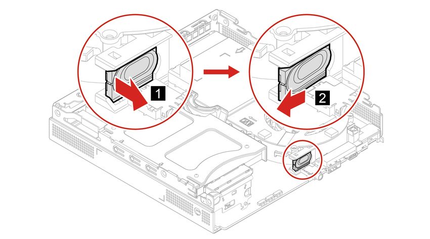
ii M70q Hardware Maintenance Manual
About this manual
This manual provides service and reference information for ThinkCentre® computers listed on the front cover.

Illustrations in this manual might look different from your product.

Use this manual along with the advanced diagnostic tests to troubleshoot problems.

Important: This manual is intended only for trained service technicians who are familiar with ThinkCentre
computers. Use this manual along with the advanced diagnostic tests to troubleshoot problems effectively.
Before servicing a ThinkCentre computer, be sure to read and understand Chapter 1 “Important safety
information” on page 1.

© Copyright Lenovo 2021                                                                                     iii
iv M70q Hardware Maintenance Manual
Chapter 1. Important safety information

General safety
Follow these rules to ensure general safety:
• Observe good housekeeping in the area of the machines during and after maintenance.
• When lifting any heavy object:
    1. Ensure you can stand safely without slipping.
    2. Distribute the weight of the object equally between your feet.
    3. Use a slow lifting force. Never move suddenly or twist when you attempt to lift.
    4. Lift by standing or by pushing up with your leg muscles; this action removes the strain from the
       muscles in your back.

        Attention: Do not attempt to lift any objects that weigh more than 16 kg (35 lb) or objects that you
        think are too heavy for you.
• Do not perform any action that causes hazards to the customer, or that makes the equipment unsafe.
• Before you start the machine, ensure that other service representatives and the customer's personnel are
  not in a hazardous position.
• Place removed covers and other parts in a safe place, away from all personnel, while you are servicing the
  machine.
• Keep your tool case away from walk areas so that other people will not trip over it.
• Do not wear loose clothing that can be trapped in the moving parts of a machine. Ensure that your sleeves
  are fastened or rolled up above your elbows. If your hair is long, fasten it.
• Insert the ends of your necktie or scarf inside clothing or fasten it with a nonconductive clip, approximately
  8 centimeters (3 inches) from the end.
• Do not wear jewelry, chains, metal-frame eyeglasses, or metal fasteners for your clothing.
   Remember: Metal objects are good electrical conductors.
• Wear safety glasses when you are: hammering, drilling, soldering, cutting wire, attaching springs, using
  solvents, or working in any other conditions that might be hazardous to your eyes.
• After service, reinstall all safety shields, guards, labels, and ground wires. Replace any safety device that
  is worn or defective.
• Reinstall all covers correctly before returning the machine to the customer.

CAUTION:

Keep fingers and other parts of your body away from hazardous, moving parts. If you suffer an injury,
seek medical care immediately.

CAUTION:

Avoid contact with hot components inside the computer. During operation, some components
become hot enough to burn the skin. Before you open the computer cover, turn off the computer,
disconnect power, and wait approximately 10 minutes for the components to cool.

© Copyright Lenovo 2021                                                                                           1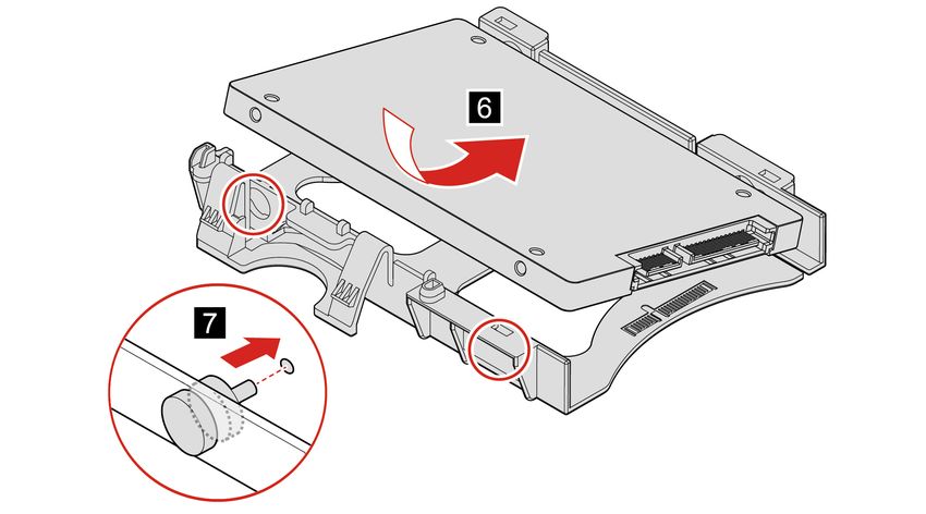
Electrical safety

CAUTION:
Electrical current from power, telephone, and communication cables can be hazardous. To avoid
personal injury or equipment damage, disconnect the attached power cords, telecommunication
systems, networks, and modems before you open the computer covers, unless instructed otherwise
in the installation and configuration procedures.

Observe the following rules when working on electrical equipment.

Important: Use only approved tools and test equipment. Some hand tools have handles covered with a soft
material that does not insulate you when working with live electrical currents. Many customers have, near
their equipment, rubber floor mats that contain small conductive fibers to decrease electrostatic discharges.
Do not use this type of mat to protect yourself from electrical shock.
• Find the room emergency power-off (EPO) switch, disconnecting switch, or electrical outlet. If an electrical
  accident occurs, you can then operate the switch or unplug the power cord quickly.
• Do not work alone under hazardous conditions or near equipment that has hazardous voltages.
• Disconnect all power before:
    – Performing a mechanical inspection
    – Working near power supplies
    – Removing or installing Field Replaceable Units (FRUs)
• Before you start to work on the machine, unplug the power cord. If you cannot unplug it, ask the customer
  to power-off the wall box that supplies power to the machine and to lock the wall box in the off position.
• If you need to work on a machine that has exposed electrical circuits, observe the following precautions:
    – Ensure that another person, familiar with the power-off controls, is near you.
      Remember: Another person must be there to switch off the power, if necessary.
    – Use only one hand when working with powered-on electrical equipment; keep the other hand in your
      pocket or behind your back.
      Remember: There must be a complete circuit to cause electrical shock. By observing the above rule,
      you may prevent a current from passing through your body.
    – When using a tester, set the controls correctly and use the approved probe leads and accessories for
      that tester.
    – Stand on suitable rubber mats (obtained locally, if necessary) to insulate you from grounds such as
      metal floor strips and machine frames.
    Observe the special safety precautions when you work with very high voltages; these instructions are in
    the safety sections of maintenance information. Use extreme care when measuring high voltages.
• Regularly inspect and maintain your electrical hand tools for safe operational condition.
• Do not use worn or broken tools and testers.
• Never assume that power has been disconnected from a circuit. First, check that it has been powered-off.
• Always look carefully for possible hazards in your work area. Examples of these hazards are moist floors,
  nongrounded power extension cables, power surges, and missing safety grounds.
• Do not touch live electrical circuits with the reflective surface of a plastic dental mirror. The surface is
  conductive; such touching can cause personal injury and machine damage.

2    M70q Hardware Maintenance Manual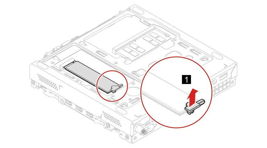
• Do not service the following parts with the power on when they are removed from their normal operating
  places in a machine:
  – Power supply units
  – Pumps
  – Blowers and fans
  – Motor generators
  and similar units. (This practice ensures correct grounding of the units.)
• If an electrical accident occurs:
  – Use caution; do not become a victim yourself.
  – Switch off power.
  – Send another person to get medical aid.

Safety inspection guide
The intent of this inspection guide is to assist you in identifying potentially unsafe conditions on these
products. Each machine, as it was designed and built, had required safety items installed to protect users
and service personnel from injury. This guide addresses only those items. However, good judgment should
be used to identify potential safety hazards due to attachment of features or options not covered by this
inspection guide.

If any unsafe conditions are present, you must determine how serious the apparent hazard could be and
whether you can continue without first correcting the problem.

Consider these conditions and the safety hazards they present:
• Electrical hazards, especially primary power (primary voltage on the frame can cause serious or fatal
  electrical shock).
• Explosive hazards, such as a damaged CRT face or bulging capacitor
• Mechanical hazards, such as loose or missing hardware

The guide consists of a series of steps presented in a checklist. Begin the checks with the power off, and the
power cord disconnected.

Checklist:
 1. Check exterior covers for damage (loose, broken, or sharp edges).
 2. Power-off the computer. Disconnect the power cord.
 3. Check the power cord for:
    a. A third-wire ground connector in good condition. Use a meter to measure third-wire ground
       continuity for 0.1 ohm or less between the external ground pin and frame ground.
    b. The power cord should be the appropriate type as specified in the parts listings.
    c. Insulation must not be frayed or worn.
 4. Remove the cover.
 5. Check for any obvious alterations. Use good judgment as to the safety of any alterations.
 6. Check inside the unit for any obvious unsafe conditions, such as metal filings, contamination, water or
    other liquids, or signs of fire or smoke damage.
 7. Check for worn, frayed, or pinched cables.

                                                                           Chapter 1. Important safety information   3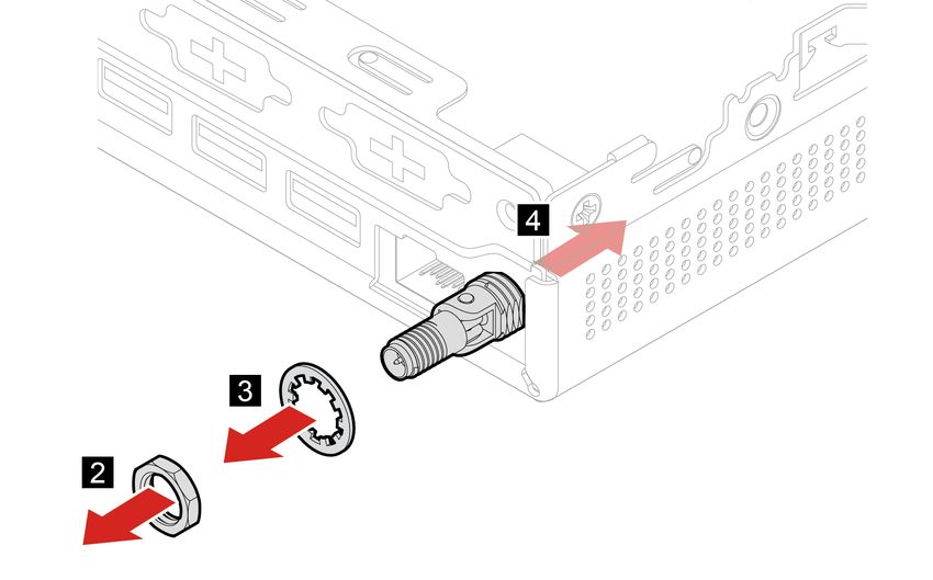
8. Check that the power-supply cover fasteners (screws or rivets) have not been removed or tampered
       with.

Handling electrostatic discharge-sensitive devices
Any computer part containing transistors or integrated circuits (ICs) should be considered sensitive to
electrostatic discharge (ESD). ESD damage can occur when there is a difference in charge between objects.
Protect against ESD damage by equalizing the charge so that the machine, the part, the work mat, and the
person handling the part are all at the same charge.

Notes:
    1. Use product-specific ESD procedures when they exceed the requirements noted here.
    2. Make sure that the ESD protective devices you use have been certified (ISO 9000) as fully effective.

When handling ESD-sensitive parts:
• Keep the parts in protective packages until they are inserted into the product.
• Avoid contact with other people while handling the part.
• Wear a grounded wrist strap against your skin to eliminate static on your body.
• Prevent the part from touching your clothing. Most clothing is insulative and retains a charge even when
  you are wearing a wrist strap.
• Use the black side of a grounded work mat to provide a static-free work surface. The mat is especially
  useful when handling ESD-sensitive devices.
• Select a grounding system, such as those listed below, to provide protection that meets the specific
  service requirement.

     Note: The use of a grounding system is desirable but not required to protect against ESD damage.
     – Attach the ESD ground clip to any frame ground, ground braid, or green-wire ground.
     – Use an ESD common ground or reference point when working on a double-insulated or battery-
       operated system. You can use coax or connector-outside shells on these systems.
     – Use the round ground-prong of the ac plug on ac-operated computers.

Grounding requirements
Electrical grounding of the computer is required for operator safety and correct system function. Proper
grounding of the electrical outlet can be verified by a certified electrician.

Safety notices (multi-lingual translations)
The caution and danger safety notices in this section are provided in the following languages:
• English
• Arabic
• Brazilian/Portuguese
• Chinese (simplified)
• Chinese (traditional)
• French
• German
• Hebrew

4     M70q Hardware Maintenance Manual
• Italian
• Korean
• Spanish
DANGER
Electrical current from power, telephone and communication cables is hazardous.
To avoid a shock hazard:
• Do not connect or disconnect any cables or perform installation, maintenance, or reconfiguration
of this product during an electrical storm.
• Connect all power cords to a properly wired and grounded electrical outlet.
• Connect to properly wired outlets any equipment that will be attached to this product.
• When possible, use one hand only to connect or disconnect signal cables.
• Never turn on any equipment when there is evidence of fire, water, or structural damage.
• Disconnect the attached power cords, telecommunications systems, networks, and modems
before you open the device covers, unless instructed otherwise in the installation and configuration
procedures.
• Connect and disconnect cables as described in the following tables when installing, moving, or
opening covers on this product or attached devices.
To Connect To Disconnect
1. Turn everything OFF. 1. Turn everything OFF.
2. First, attach all cables to devices. 2. First, remove power cords from outlet.
3. Attach signal cables to connectors. 3. Remove signal cables from connectors.
4. Attach power cords to outlet. 4. Remove all cables from devices.
5. Turn device ON.
CAUTION:
When replacing the lithium battery, use only Part Number 45C1566 or an equivalent type battery
recommended by the manufacturer. If your system has a module containing a lithium battery, replace
it only with the same module type made by the same manufacturer. The battery contains lithium and
can explode if not properly used, handled, or disposed of. Do not:
• Throw or immerse into water
• Heat to more than 100°C (212°F)
• Repair or disassemble
Dispose of the battery as required by local ordinances or regulations.
Chapter 1. Important safety information 5CAUTION:
When laser products (such as CD-ROMs, DVD-ROM drives, fiber optic devices, or transmitters) are
installed, note the following:
• Do not remove the covers. Removing the covers of the laser product could result in exposure to
hazardous laser radiation. There are no serviceable parts inside the device.
• Use of controls or adjustments or performance of procedures other than those specified herein
might result in hazardous radiation exposure.
DANGER
Some laser products contain an embedded Class 3A or Class 3B laser diode. Note the following:
Laser radiation when open. Do not stare into the beam, do not view directly with optical
instruments, and avoid direct exposure to the beam.
≥18 kg (37 lb) ≥32 kg (70.5 lb) ≥55 kg (121.2 lb)
CAUTION:
Use safe practices when lifting.
CAUTION:
The power control button on the device and the power switch on the power supply do not turn off the
electrical current supplied to the device. The device also might have more than one power cord. To
remove all electrical current from the device, ensure that all power cords are disconnected from the
power source.
2
1
6 M70q Hardware Maintenance ManualChapter 1. Important safety information 7
≥18 kg (37 lb)              ≥32 kg (70.5 lb)   ≥55 kg (121.2 lb)

                                                                   2
                                                                   1

8   M70q Hardware Maintenance Manual
PERIGO
A corrente elétrica proveniente de cabos de alimentação, de telefone e de comunicações é perigosa.
Para evitar risco de choque elétrico:
• Não conecte nem desconecte nenhum cabo ou execute instalação, manutenção ou reconfiguração deste
produto durante uma tempestade com raios.
• Conecte todos os cabos de alimentação a tomadas elétricas corretamente instaladas e aterradas.
• Todo equipamento que for conectado a este produto deve ser conectado a tomadas corretamente
instaladas.
• Quando possível, utilize apenas uma das mãos para conectar ou desconectar cabos de sinal.
• Nunca ligue nenhum equipamento quando houver evidência de fogo, água ou danos estruturais.
• Antes de abrir tampas de dispositivos, desconecte cabos de alimentação, sistemas de telecomunicação,
redes e modems conectados, a menos que especificado de maneira diferente nos procedimentos de
instalação e configuração.
• Conecte e desconecte os cabos conforme descrito na tabela apresentada a seguir ao instalar, mover ou
abrir tampas deste produto ou de dispositivos conectados.
Para Conectar: Para Desconectar:
1. DESLIGUE Tudo. 1. DESLIGUE Tudo.
2. Primeiramente, conecte todos os cabos aos 2. Primeiramente, remova os cabos de alimentação das
dispositivos. tomadas.
3. Conecte os cabos de sinal aos conectores. 3. Remova os cabos de sinal dos conectores.
4. Conecte os cabos de alimentação às tomadas. 4. Remova todos os cabos dos dispositivos.
5. LIGUE os dispositivos.
CUIDADO:
Ao substituir a bateria de lítio, utilize apenas uma bateria com Número de Peça 45C1566 ou um tipo de
bateria equivalente recomendado pelo Se o seu sistema possui um módulo com uma bateria de lítio,
substitua-o apenas por um módulo do mesmo tipo e do mesmo fabricante. A bateria contém lítio e
pode explodir se não for utilizada, manuseada ou descartada de maneira correta.
Não:
• Jogue ou coloque na água
• Aqueça a mais de 100°C (212°F)
• Conserte nem desmonte
Descarte a bateria conforme requerido pelas leis ou regulamentos locais.
PRECAUCIÓN:
Chapter 1. Important safety information 9Quando produtos a laser (como unidades de CD-ROMs, unidades de DVD-ROM, dispositivos de fibra ótica
ou transmissores) estiverem instalados, observe o seguinte:
• Não remova as tampas. A remoção das tampas de um produto a laser pode resultar em exposição
prejudicial à radiação de laser. Não existem peças que podem ser consertadas no interior do dispositivo.
• A utilização de controles ou ajustes ou a execução de procedimentos diferentes dos especificados aqui
pode resultar em exposição prejudicial à radiação.
PERIGO
Alguns produtos a laser contêm diodo de laser integrado da Classe 3A ou da Classe 3B. Observe o seguinte:
Radiação a laser quando aberto. Não olhe diretamente para o feixe a olho nu ou com instrumentos ópticos e
evite exposição direta ao feixe.
≥18 kg (37 lb) ≥32 kg (70.5 lb) ≥55 kg (121.2 lb)
CUIDADO:
Utilize procedimentos de segurança para levantar equipamentos.
CUIDADO:
O botão de controle de alimentação do dispositivo e o botão para ligar/desligar da fonte de alimentação não
desligam a corrente elétrica fornecida ao dispositivo. O dispositivo também pode ter mais de um cabo de
alimentação. Para remover toda a corrente elétrica do dispositivo, assegure que todos os cabos de
alimentação estejam desconectados da fonte de alimentação.
2
1
10 M70q Hardware Maintenance ManualChapter 1. Important safety information 11
2
1

12   M70q Hardware Maintenance Manual
Chapter 1. Important safety information 13
2
1

DANGER

Le courant électrique provenant de l'alimentation, du téléphone et des câbles de transmission peut présenter
un danger.

Pour éviter tout risque de choc électrique :
• Ne manipulez aucun câble et n'effectuez aucune opération d'installation, d'entretien ou de reconfiguration
  de ce produit au cours d'un orage.
• Branchez tous les cordons d'alimentation sur un socle de prise de courant correctement câblé et mis à la
  terre.
• Branchez sur des socles de prise de courant correctement câblés tout équipement connecté à ce produit.
• Lorsque cela est possible, n'utilisez qu'une seule main pour connecter ou déconnecter les câbles
  d'interface.
• Ne mettez jamais un équipement sous tension en cas d'incendie ou d'inondation, ou en présence de
  dommages matériels.
• Avant de retirer les carters de l'unité, mettez celle-ci hors tension et déconnectez ses cordons
  d'alimentation, ainsi que les câbles qui la relient aux réseaux, aux systèmes de télécommunication et aux
  modems (sauf instruction contraire mentionnée dans les procédures d'installation et de configuration).
• Lorsque vous installez, que vous déplacez, ou que vous manipulez le présent produit ou des
  périphériques qui lui sont raccordés, reportez-vous aux instructions ci-dessous pour connecter et
  déconnecter les différents cordons.

14   M70q Hardware Maintenance Manual
Connexion                                                 Déconnexion

  1. Mettez les unités HORS TENSION.                        1. Mettez les unités HORS TENSION.
  2. Commencez par brancher tous les cordons sur les        2. Débranchez les cordons d'alimentation des prises.
     unités.                                                3. Débranchez les câbles d'interface des connecteurs.
  3. Branchez les câbles d'interface sur des                4. Débranchez tous les câbles des unités.
     connecteurs.
  4. Branchez les cordons d'alimentation sur des prises.
  5. Mettez les unités SOUS TENSION.

ATTENTION:

Remplacer la pile au lithium usagée par une pile de référence identique exclusivement, (référence
45C1566), ou suivre les instructions du fabricant qui en définit les équivalences. Si votre système est
doté d'un module contenant une pile au lithium, vous devez le remplacer uniquement par un module
identique, produit par le même fabricant. La pile contient du lithium et peut exploser en cas de
mauvaise utilisation, de mauvaise manipulation ou de mise au rebut inappropriée.

Ne pas :

• la jeter à l'eau,
• l'exposer à des températures supérieures à 100°C,
• chercher à la réparer ou à la démonter.

Ne pas mettre la pile à la poubelle. Pour la mise au rebut, se reporter à la réglementation en vigueur.

ATTENTION:

Si des produits à laser (tels que des unités de CD-ROM, de DVD-ROM, des unités à fibres optiques, ou
des émetteurs) sont installés, prenez connaissance des informations suivantes :
• Ne retirez pas le carter. En ouvrant l'unité de CD-ROM ou de DVD-ROM, vous vous exposez au
  rayonnement dangereux du laser. Aucune pièce de l'unité n'est réparable.
• Pour éviter tout risque d'exposition au rayon laser, respectez les consignes de réglage et
  d'utilisation des commandes, ainsi que les procédures décrites dans le présent manuel.

DANGER

Certains produits à laser contiennent une diode à laser intégrée de classe 3A ou 3B. Prenez
connaissance des informations suivantes:

Rayonnement laser lorsque le carter est ouvert. Evitez toute expositiondirecte au rayon laser. Evitez
de regarder fixement le faisceau ou del'observer à l'aide d'instruments optiques.

                                                                             Chapter 1. Important safety information   15
≥18 kg (37 lb) ≥32 kg (70.5 lb) ≥55 kg (121.2 lb) ATTENTION: Soulevez la machine avec précaution. ATTENTION: L'interrupteur de contrôle d'alimentation de l'unité et l'interrupteur dubloc d'alimentation ne coupent pas le courant électrique alimentantl'unité. En outre, le système peut être équipé de plusieurs cordonsd'alimentation. Pour mettre l'unité hors tension, vous devez déconnectertous les cordons de la source d'alimentation. 2 1 VORSICHT An Netz-, Telefon- und Datenleitungen können gefährliche Spannungen anliegen. Aus Sicherheitsgründen: • Bei Gewitter an diesem Gerät keine Kabel anschließen oder lösen. Ferner keine Installations-, Wartungs- oder Rekonfigurationsarbeiten durchführen. • Gerät nur an eine Schutzkontaktsteckdose mit ordnungsgemäß geerdetem Schutzkontakt anschließen. • Alle angeschlossenen Geräte ebenfalls an Schutzkontaktsteckdosen mit ordnungsgemäß geerdetem Schutzkontakt anschließen. • Die Signalkabel nach Möglichkeit einhändig anschließen oder lösen, um einen Stromschlag durch Berühren von Oberflächen mit unterschiedlichem elektrischem Potenzial zu vermeiden. • Geräte niemals einschalten, wenn Hinweise auf Feuer, Wasser oder Gebäudeschäden vorliegen. 16 M70q Hardware Maintenance Manual
• Die Verbindung zu den angeschlossenen Netzkabeln, Telekommunikationssystemen, Netzwerken
  und Modems ist vor dem Öffnen des Gehäuses zu unterbrechen, sofern in den Installations- und
  Konfigurationsprozeduren keine anders lautenden Anweisungen enthalten sind.
• Zum Installieren, Transportieren und Öffnen der Abdeckungen des Computers oder der
  angeschlossenen Einheiten die Kabel gemäß der folgenden Tabelle anschließen und abziehen.

 Zum Anschließen der Kabel gehen Sie wie folgt vor        Zum Abziehen der Kabel gehen Sie wie folgt vor

  1. Schalten Sie alle Einheiten AUS.                      1. Schalten Sie alle Einheiten AUS.
  2. Schließen Sie erst alle Kabel an die Einheiten an.    2. Ziehen Sie zuerst alle Netzkabel aus den
  3. Schließen Sie die Signalkabel an die Buchsen an.         Netzsteckdosen.

  4. Schließen Sie die Netzkabel an die Steckdose an.      3. Ziehen Sie die Signalkabel aus den Buchsen.

  5. Schalten Sie die Einheit EIN.                         4. Ziehen Sie alle Kabel von den Einheiten ab.

CAUTION:

Eine verbrauchte Lithiumbatterie nur durch eine Batterie mit der Teilenummer 45C1566 oder eine
gleichwertige, vom Hersteller empfohlene Batterie ersetzen. Enthält das System ein Modul mit einer
Lithiumbatterie, dieses nur durch ein Modul desselben Typs und von demselben Hersteller ersetzen. Die
Batterie enthält Lithium und kann bei unsachgemäßer Verwendung, Handhabung oder Entsorgung
explodieren.

Die Batterie nicht:
• mit Wasser in Berührung bringen.
• über 100 C erhitzen.
• reparieren oder zerlegen.

Die örtlichen Bestimmungen für die Entsorgung von Sondermüll beachten.

ACHTUNG:

Bei der Installation von Lasergeräten (wie CD-ROM-Laufwerken, DVD- aufwerken, Einheiten mit
Lichtwellenleitertechnik oder Sendern) Folgendes beachten:
• Die Abdeckungen nicht entfernen. Durch Entfernen der Abdeckungen des Lasergeräts können
  gefährliche Laserstrahlungen freigesetzt werden. Das Gerät enthält keine zu wartenden Teile.
• Werden Steuerelemente, Einstellungen oder Durchführungen von Prozeduren anders als hier
  angegeben verwendet, kann gefährliche Laserstrahlung auftreten.

VORSICHT

Einige Lasergeräte enthalten eine Laserdiode der Klasse 3A oder 3B. Beachten Sie Folgendes:

                                                                            Chapter 1. Important safety information   17
Laserstrahlung bei geöffneter Verkleidung. Nicht in den Strahl blicken. Keine Lupen oder Spiegel
verwenden. Strahlungsbereich meiden.
≥18 kg ≥32 kg ≥55 kg
ACHTUNG:
Arbeitsschutzrichtlinien beim Anheben der Maschine beachten.
ACHTUNG:
Mit dem Netzschalter an der Einheit und am Netzteil wird die Stromversorgung für die Einheit nicht
unterbrochen. Die Einheit kann auch mit mehreren Netzkabeln ausgestattet sein. Um die
Stromversorgung für die Einheit vollständig zu unterbrechen, müssen alle zum Gerät führenden
Netzkabel vom Netz getrennt werden.
2
1
18 M70q Hardware Maintenance ManualChapter 1. Important safety information 19
2
                                                                                          1

PERICOLO

La corrente elettrica proveniente dai cavi di alimentazione, del telefono e di comunicazione può essere
pericolosa.

Per evitare il rischio di scosse elettriche:

20   M70q Hardware Maintenance Manual
• Non collegare o scollegare qualsiasi cavo oppure effettuare l'installazione, la manutenzione o la
riconfigurazione del prodotto durante un temporale.
• Collegare tutti i fili elettrici a una presa di alimentazione correttamente cablata e dotata di messa a
terra.
• Collegare alle prese elettriche appropriate tutte le apparecchiature che verranno utilizzate per
questo prodotto.
• Se possibile, utilizzare solo una mano per collegare o scollegare i cavi di segnale.
• Non accendere assolutamente apparecchiature in presenza di incendi, perdite d'acqua o danno
strutturale.
• Scollegare i cavi di alimentazione, i sistemi di telecomunicazione, le reti e il modem prima di aprire i
coperchi del dispositivo, salvo istruzioni contrarie relative alle procedure di installazione e
configurazione.
• Collegare e scollegare i cavi come descritto nella seguente tabella quando vengono effettuate
operazioni di installazione, spostamento o apertura dei coperchi di questo prodotto o delle unità
collegate.
Per collegarsi Per scollegarsi
1. SPEGNERE le apparecchiature. 1. SPEGNERE le apparecchiature.
2. Innanzitutto, collegare tutti i cavi alle unità. 2. Innanzitutto, rimuovere i cavi di alimentazione dalla
3. Collegare i cavi di segnale ai connettori. presa.
4. Collegare i cavi di alimentazione alla presa. 3. Rimuovere i cavi di segnale dai connettori.
5. Accendere l'unità. 4. Rimuovere tutti i cavi dalle unità.
ATTENZIONE:
Quando si sostituisce la batteria al litio, utilizzare solo il Numero parte 45C1566 o un tipo di batteria
equivalente consigliato dal produttore. Se sul sistema è presente un modulo che contiene una batteria
al litio, sostituirlo solo con un tipo di modulo dello stesso tipo della stessa casa di produzione. La
batteria contiene litio e può esplodere se usata, maneggiata o smaltita in modo non corretto.
Non:
• Gettare o immergere la batteria nell'acqua
• Riscaldarla ad una temperatura superiore ai 100 gradi C (212 gradi F)
• Smontarla, ricaricarla o tentare di ripararla
Le batterie usate vanno smaltite in accordo alla normativa in vigore (DPR 915/82 e successive
disposizioni e disposizioni locali).
ATTENZIONE:
Quando vengono installati prodotti laser (quali CD-ROM, unità DVD-ROM, unità a fibre ottiche o
trasmittenti), tener presente quanto segue:
Chapter 1. Important safety information 21• Non rimuovere gli sportelli. L'apertura di un'unità laser può determinare l'esposizione a radiazioni
laser pericolose. All'interno dell'unità non vi sono parti su cui effettuare l'assistenza tecnica.
• L'utilizzo di controlli, regolazioni o l'esecuzione di procedure non descritti nel presente manuale
possono provocare l'esposizione a radiazioni pericolose.
PERICOLO
Alcune unità laser contengono un diodo laser di Classe 3A o Classe 3B. Tener presente quanto segue:
Aprendo l'unità vengono emesse radiazioni laser. Non fissare il fascio, non guardarlo direttamente
con strumenti ottici ed evitare l'esposizione al fascio.
≥18 kg ≥32 kg ≥55 kg
ATTENZIONE:
Prestare attenzione nel sollevare l'apparecchiatura.
ATTENZIONE:
Il pulsante di controllo dell'alimentazione presente sull'unità e l'interruttore dell'alimentatore non
disattivano l'alimentazione corrente fornita all'unità. E' possibile che l'unità disponga di più cavi di
alimentazione. Per disattivare l'alimentazione dall'unità, accertarsi che tutti i cavi di alimentazione
siano scollegati dalla fonte di alimentazione.
2
1
22 M70q Hardware Maintenance ManualChapter 1. Important safety information 23
2
1

PELIGRO

La corriente eléctrica procedente de cables de alimentación, teléfonos y cables de comunicación puede ser
peligrosa.

Para evitar el riesgo de descarga eléctrica:
• No conecte ni desconecte los cables ni realice ninguna tarea de instalación, mantenimiento o
  reconfiguración de este producto durante una tormenta eléctrica.
• Conecte todos los cables de alimentación a tomas de corriente debidamente cableadas y
  conectadas a tierra.
• Cualquier equipo que se conecte a este producto también debe conectarse a tomas de corriente
  debidamente cableadas.
• Siempre que sea posible, utilice una sola mano para conectar o desconectar los cables de señal.

24   M70q Hardware Maintenance Manual
• No encienda nunca un equipo cuando hay señales de fuego, agua o daños estructurales.
• Desconecte los cables de alimentación, los sistemas de telecomunicaciones, las redes y los
  módems conectados antes de abrir las cubiertas de los dispositivos, a menos que se indique lo
  contrario en los procedimientos de instalación y configuración.
• Conecte y desconecte los cables, como se describe en la tabla siguiente, cuando instale, mueva o
  abra las cubiertas de este producto o de los dispositivos conectados.

 Para conectar                                           Para desconectar

  1. APÁGUELO todo.                                       1. APÁGUELO todo.
  2. En primer lugar, conecte todos los cables a los      2. En primer lugar, desenchufe los cables de
     dispositivos.                                           alimentación de las tomas de corriente.
  3. Conecte los cables de señal a los conectores.        3. Desconecte los cables de señal de los conectores.
  4. Enchufe los cables de alimentación a las tomas de    4. Desconecte todos los cables de los dispositivos.
     corriente.
  5. Encienda el dispositivo.

PRECAUCIÓN:

Cuando sustituya una batería de litio, utilice solamente una batería número de pieza 45C1566 u otra
de tipo equivalente recomendada por el fabricante. Si su sistema dispone de un módulo que contiene
una batería de litio, reemplácelo sólo con el mismo tipo de módulo, del mismo fabricante. La batería
contiene litio y puede explotar si no se utiliza, manipula o desecha correctamente.

No debe:
• Arrojarla al agua o sumergirla en ella
• Exponerla a temperaturas superiores a 100°C (212°F)
• Repararla o desmontarla

Deshágase de la batería según especifiquen las leyes o normas locales.

PRECAUCIÓN:

Cuando haya productos láser (como unidades de CD-ROM, unidades de DVD, dispositivos de fibra
óptica o transmisores) instalados, tenga en cuenta lo siguiente:
• No quite las cubiertas. Si quita las cubiertas del producto láser, podría quedar expuesto a radiación
  láser peligrosa. Dentro del dispositivo no existe ninguna pieza que requiera servicio técnico.
• Si usa controles o ajustes o realiza procedimientos que no sean los especificados aquí, podría
  exponerse a radiaciones peligrosas.

PELIGRO

                                                                           Chapter 1. Important safety information   25
Algunos productos láser tienen incorporado un diodo láser de clase 3A o clase 3B. Tenga en cuenta lo
siguiente:
Cuando se abre, queda expuesto a radiación láser. No mire directamente al rayo láser, ni siquiera con
instrumentos ópticos, y evite exponerse directamente al rayo láser.
≥18 kg ≥32 kg ≥55 kg
PRECAUCIÓN:
Adopte procedimientos seguros al levantar el equipo.
PRECAUCIÓN:
El botón de control de alimentación del dispositivo y el interruptor de alimentación de la fuente de
alimentación no desconectan la corriente eléctrica suministrada al dispositivo. Además, el dispositivo
podría tener más de un cable de alimentación. Para suprimir toda la corriente eléctrica del dispositivo,
asegúrese de que todos los cables de alimentación estén desconectados de la toma de corriente.
2
1
26 M70q Hardware Maintenance ManualChapter 2. Product overview Front 1. ThinkCentre® LED 2. Power button 3. Storage drive activity indicator 4. USB-C® (3.2 Gen 1) connector 5. Always On USB 3.2 connector Gen 2 6. Headset connector © Copyright Lenovo 2021 27
Rear

 1. Optional connectors*                2. Security-lock slot

 3. Wi-Fi® antenna slot*                4. Ethernet connector
 5. USB 3.2 connector Gen 2             6. USB 3.2 connector Gen 1
 7. USB 3.2 connector Gen 1             8. HDMITM 1.4 out connector
 9. USB 3.2 connector Gen 1             10. DisplayPort® 1.4 out connector

 11. Power adapter connector

* for selected models

28   M70q Hardware Maintenance Manual
Chapter 3. Call Amazon Helpdesk
If you have tried to correct the problem yourself and still need help, you can call Amazon Helpdesk.

Before you contact service
Prepare the following before you contact Amazon Helpdesk:
    1. Record the problem symptoms and details:
      • What is the problem? Is it continuous or intermittent?
      • Any error message or error code?
      • What operating system are you using? Which version?
      • Which software applications were running at the time of the problem?
      • Can the problem be reproduced? If so, how?
    2. Record the system information:
      • Product name
      • Machine type and serial number
         The following illustration shows where to find the machine type and serial number of your computer.

Amazon Helpdesk
You can get help and information from Amazon Helpdesk.

Services not covered
•    Replacement or use of parts not manufactured for or by Lenovo or nonwarranted parts
•    Identification of software problem sources
•    Changes, modifications, or upgrades to device drivers
•    Installation and maintenance of network operating systems (NOS)
•    Installation and maintenance of programs

© Copyright Lenovo 2021                                                                                    29
30 M70q Hardware Maintenance Manual
Chapter 4. Hardware removal and installation
This chapter provides instructions on how to remove and install hardware for your computer.

Handling static-sensitive devices
Do not open the static-protective package containing the new part until the defective part has been removed
and you are ready to install the new part. Static electricity, although harmless to you, can seriously damage
computer components and options.

When you handle options and other computer components, take these precautions to avoid static-electricity
damage:
• Limit your movement. Movement can cause static electricity to build up around you.
• Always handle options and other computer components carefully. Handle PCI/PCIe cards, memory
  modules, system boards, and microprocessors by the edges. Never touch any exposed circuitry.
• Prevent others from touching the options and other computer components.
• Touch the static-protective package containing the part to a metal expansion-slot cover or other
  unpainted metal surface on the computer for at least two seconds. This reduces static electricity from the
  package and your body before you install or replace a new part.
• When possible, remove the new part from the static-protective package, and install it directly in the
  computer without setting the part down. When this is not possible, place the static-protective package on
  a smooth, level surface and place the part on the package.
• Do not place the part on the computer cover or other metal surface.

Service tool kit
Ensure that the following common service tool kit is prepared before you service the computer.

 No.      Tool name                                         Tool type

 1        Phillips-head screwdriver                         Common tool
 2        Torx-head screwdriver (for new Intel Xeon CPUs)   Common tool

 3        Pry tools                                         Common tool

 4        Conductive tweezers                               Common tool
 5        Isolated tweezers                                 Common tool
 6        Hexagonal socket                                  Common tool

 7        Silicone grease                                   Consumable tool

 8        Polyamide tape                                    Consumable tool

 9        Mylar tape                                        Consumable tool

 10       Eraser                                            Consumable tool
 11       Electrical tape                                   Consumable tool

 12       Double-sided tape                                 Consumable tool

 13       Conductive tape                                   Consumable tool

© Copyright Lenovo 2021                                                                                    31
Note: The silicone grease can be applied to the surfaces of the microprocessor and heat sink to eliminate air
gaps. The hexagonal socket is used to pick up the antenna connectors.

Major hardware
Your computer contains the following major hardware:

32   M70q Hardware Maintenance Manual
Number                                Description
  1      Computer cover
  2      Heat sink
  3      System fan
  4      Coin-cell battery
  5      Internal speaker
  6      Antenna bracket
  7      Wi-Fi card
  8      Wi-Fi card shield
  9      Memory module

  10     Chassis
  11     M.2 solid-state drive
  12     Bottom cover
  13     Wi-Fi antenna cables
  14     Rear Wi-Fi antenna
  15     Storage drive cable

  16     Storage drive

  17     Storage drive bracket

  18     System board

  19     Microprocessor
  20     Dust shield
  21     Thumb screw
  a      Power adapter

  b      Power adapter bracket
  c      Kensington cable lock

  d      Power cord
  e      Vertical stand
  f      Keyboard
  g      Mouse
  h      External optical drive box

  i      VESA® mount bracket
  j      External optical drive

                                          Chapter 4. Hardware removal and installation   33
System board 1 Microprocessor socket 2 Coin-cell battery 3 System fan connector 4 Internal speaker connector 5 Cover presence switch connector (intrusion switch 6 SATA connector (connecting to the storage drive) connector) 7 M.2 Wi-Fi card slot 8 Serial (COM1) connector 34 M70q Hardware Maintenance Manual
9 Clear CMOS /Recovery jumper                          10 M.2 solid-state drive slot

 11 Memory slot (DIMM 2)                                12 Memory slot (DIMM 1)

Removing and installing hardware
This section provides instructions on how to remove and install hardware for your computer. You can expand
the capabilities of your computer and maintain your computer by removing or installing hardware. To replace
any hardware, contact Amazon Helpdesk.

Attention:
• Do not open the computer cover unless you are a trained service technician. Otherwise, a chassis
  intrusion detection switch will be triggered, rendering the device untrusted and potentially unusable.
• Do not open your computer or attempt any repair before reading and understanding the Chapter 1
  “Important safety information” on page 1.

External options
You can connect external options to your computer, such as external speakers, a printer, or a scanner. For
some external options, you must install additional software in addition to making the physical connection.
When installing an external option, see Chapter 2 “Product overview” on page 27 to identify the required
connector. Then, use the instructions that come with the option to help you make the connection and install
any required software or device drivers.

Power cord and power adapter

Prerequisite
Before you start, read Chapter 1 “Important safety information” on page 1 and print the following
instructions.

Replacement procedure
 1. Remove any media from the drives and turn off all connected devices and the computer.
 2. Disconnect the power cord from the electrical outlet and disconnect all cables from the computer.
 3. Replace the power adapter.

                                                                    Chapter 4. Hardware removal and installation   35
36 M70q Hardware Maintenance Manual
4. Reconnect the external cables and power adapter to the corresponding connectors on the computer.

Power adapter bracket

Prerequisite
Before you start, read Chapter 1 “Important safety information” on page 1 and print the following
instructions.

Replacement procedure
 1. Remove any media from the drives and turn off all connected devices and the computer.
 2. Disconnect all power cords from electrical outlets and disconnect all cables from the computer.
 3. Remove the power adapter from the bracket.

                                                                   Chapter 4. Hardware removal and installation   37
4. Replace the power adapter bracket. 5. Install the power adapter into the bracket. 6. Reconnect the external cables and power adapter to the corresponding connectors on the computer. Vertical stand Prerequisite Before you start, read Chapter 1 “Important safety information” on page 1 and print the following instructions. Replacement procedure 1. Remove any media from the drives and turn off all connected devices and the computer. 2. Disconnect all power cords from electrical outlets and disconnect all cables from the computer. 3. Replace the vertical stand. 38 M70q Hardware Maintenance Manual
4. Reconnect the external cables and power adapter to the corresponding connectors on the computer.

                                                              Chapter 4. Hardware removal and installation   39
External optical drive Prerequisite Before you start, read Chapter 1 “Important safety information” on page 1 and print the following instructions. Replacement procedure 1. Remove any media from the drives and turn off all connected devices and the computer. 2. Disconnect all power cords from electrical outlets and disconnect all cables from the computer. 3. Replace the external optical drive. 40 M70q Hardware Maintenance Manual
4. Reconnect the external cables and power adapter to the corresponding connectors on the computer.

VESA mount bracket

Prerequisite
Before you start, read Chapter 1 “Important safety information” on page 1 and print the following
instructions.

Replacement procedure
 1. Remove any media from the drives and turn off all connected devices and the computer.
 2. Disconnect all power cords from electrical outlets and disconnect all cables from the computer.
 3. Replace the VESA mount bracket.

                                                                   Chapter 4. Hardware removal and installation   41
4. Reconnect the external cables and power adapter to the corresponding connectors on the computer. Dust shield Prerequisite Before you start, read Chapter 1 “Important safety information” on page 1 and print the following instructions. Replacement procedure 1. Remove any media from the drives and turn off all connected devices and the computer. 2. Disconnect all power cords from electrical outlets and disconnect all cables from the computer. 3. Replace the dust shield. 42 M70q Hardware Maintenance Manual
4. Reconnect the external cables and power adapter to the corresponding connectors on the computer.
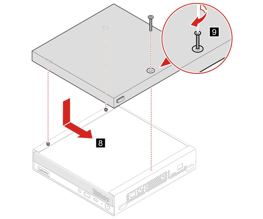
Chapter 4. Hardware removal and installation 43Computer cover Prerequisite Before you start, read Chapter 1 “Important safety information” on page 1 and print the following instructions. Before you open the computer cover, turn off the computer and wait several minutes until the computer is cool. Replacement procedure 1. Remove any media from the drives and turn off all connected devices and the computer. 2. Disconnect all power cords from electrical outlets and disconnect all cables from the computer. 3. Unlock any locking device that secures the computer cover. 4. Remove the vertical stand. See “Vertical stand” on page 38. 5. Remove the dust shield. See “Dust shield” on page 42. 6. Hold the sides of the computer and gently lay it down so that the computer cover is facing up. 7. Replace the computer cover. 44 M70q Hardware Maintenance Manual
8. Place the computer in an upright position.
9. Reinstall the removed parts. Then, reconnect the power adapter and all disconnected cables to the
computer.
Note: If a locking device is available, use it to lock the computer.
Rear Wi-Fi antenna
Prerequisite
Before you start, read Chapter 1 “Important safety information” on page 1 and print the following
instructions.
Replacement procedure
1. Remove any media from the drives and turn off all connected devices and the computer.
2. Disconnect all power cords from electrical outlets and disconnect all cables from the computer.
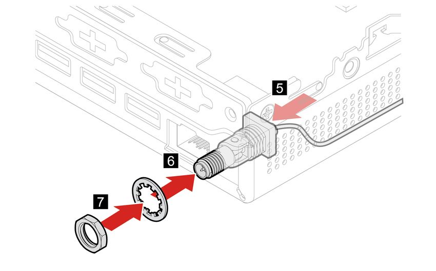
3. Replace the rear Wi-Fi antenna.
Chapter 4. Hardware removal and installation 454. Reconnect the external cables and power adapter to the corresponding connectors on the computer. Internal speaker Prerequisite Before you start, read Chapter 1 “Important safety information” on page 1 and print the following instructions. Replacement procedure 1. Remove the computer cover. See “Computer cover” on page 44. 2. Disconnect the internal-speaker cable from the internal-speaker connector on the system board. 46 M70q Hardware Maintenance Manual
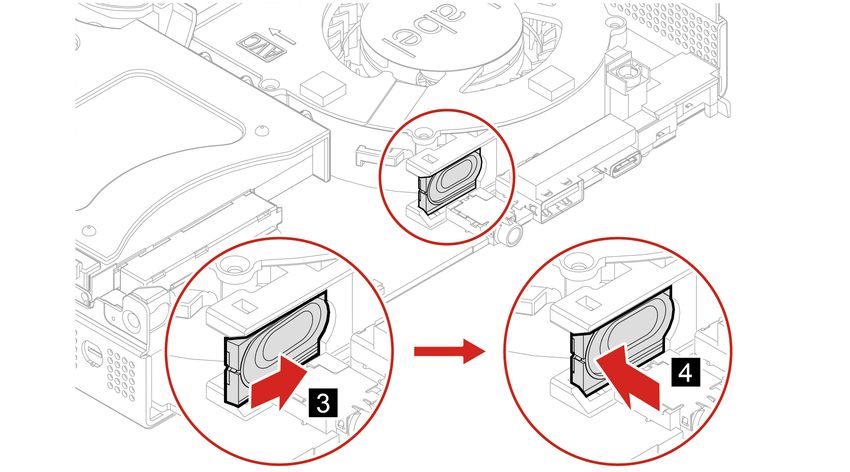
3. Replace the internal speaker.
4. Connect the internal-speaker cable to the internal-speaker connector on the system board.
5. Reinstall the removed parts. Then, reconnect the power adapter and all disconnected cables to the
computer.
System fan
Prerequisite
Before you start, read Chapter 1 “Important safety information” on page 1 and print the following
instructions.
Replacement procedure
1. Remove the computer cover. See “Computer cover” on page 44.
2. Remove the internal speaker. See “Internal speaker” on page 46.
3. Disconnect the system fan cable from the system fan connector on the system board.
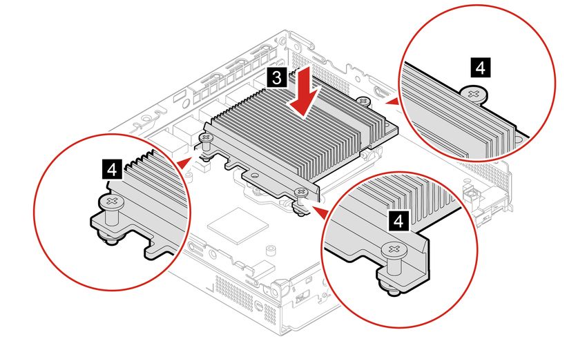
4. Replace the system fan.
Chapter 4. Hardware removal and installation 475. Connect the system fan cable to the system fan connector on the system board.
6. Reinstall the removed parts. Then, reconnect the power adapter and all disconnected cables to the
computer.
Coin-cell battery
Prerequisite
Before you start, read Chapter 1 “Important safety information” on page 1 and print the following
instructions.
Your computer has a special type of memory that maintains the date, time, and settings for built-in features,
such as parallel connector assignments (configurations). A coin-cell battery keeps this information active
when you turn off the computer.
The coin-cell battery normally requires no charging or maintenance throughout its life; however, no coin-cell
battery lasts forever. If the coin-cell battery fails, the date and time information is lost. An error message is
displayed when you turn on the computer.
Replacement procedure
1. Remove the computer cover. See “Computer cover” on page 44.
48 M70q Hardware Maintenance Manual2. Remove the system fan. See “System fan” on page 47.
3. Replace the coin-cell battery.
Chapter 4. Hardware removal and installation 494. Reinstall the removed parts. Then, reconnect the power adapter and all disconnected cables to the
computer.
5. Turn on the computer and all attached devices.
Note: When the computer is turned on for the first time after the coin-cell battery is replaced, an error
message might be displayed. This is normal after the coin-cell battery is replaced.
To dispose of the coin-cell battery, refer to the “Lithium coin-cell battery notice” in the Safety and Warranty
Guide.
Storage drive
Prerequisite
Before you start, read Chapter 1 “Important safety information” on page 1 and print the following
instructions.
Attention:
• The internal storage drive is sensitive. Inappropriate handling might cause damage and permanent loss of
data.
• When handling the internal storage drive, observe the following guidelines:
– Replace the internal storage drive only for upgrade or repair. The internal storage drive is not designed
for frequent changes or replacement.
– Before replacing the internal storage drive, make a backup copy of all the data that you want to keep.
– Do not touch the contact edge of the internal storage drive. Otherwise, the internal storage drive might
get damaged.
– Do not apply pressure to the internal storage drive.
– Do not make the internal storage drive subject to physical shocks or vibration. Put the internal storage
drive on a soft material, such as cloth, to absorb physical shocks.
Replacement procedure
1. Remove the computer cover. See “Computer cover” on page 44.
2. Replace the storage drive.
50 M70q Hardware Maintenance ManualChapter 4. Hardware removal and installation 51
3. Reinstall the removed parts. Then, reconnect the power adapter and all disconnected cables to the
    computer.

Wi-Fi card

Prerequisite
Before you start, read Chapter 1 “Important safety information” on page 1 and print the following
instructions.

Replacement procedure
 1. Remove the computer cover. See “Computer cover” on page 44.
 2. Remove the storage drive. See “Storage drive” on page 50.
 3. Replace the Wi-Fi card.

52   M70q Hardware Maintenance Manual
Chapter 4. Hardware removal and installation 53
4. Reinstall the removed parts. Then, reconnect the power adapter and all disconnected cables to the
    computer.

Bottom cover

Prerequisite
Before you start, read Chapter 1 “Important safety information” on page 1 and print the following
instructions.

Replacement procedure
 1. Remove the computer cover. See “Computer cover” on page 44.
 2. Turn over the computer so that the bottom cover is facing up.
 3. Replace the bottom cover.

54   M70q Hardware Maintenance Manual
4. Turn over the computer so that the bottom cover is facing down.
5. Reinstall the removed parts. Then, reconnect the power adapter and all disconnected cables to the
computer.
Memory module
Prerequisite
Before you start, read Chapter 1 “Important safety information” on page 1 and print the following
instructions.
Replacement procedure
1. Remove the computer cover. See “Computer cover” on page 44.
2. Remove the bottom cover. See “Bottom cover” on page 54.
3. Replace the memory module.
Chapter 4. Hardware removal and installation 554. Reinstall the removed parts. Then, reconnect the power adapter and all disconnected cables to the
computer.
M.2 solid-state drive
Prerequisite
Before you start, read Chapter 1 “Important safety information” on page 1 and print the following
instructions.
Attention:
• The M.2 solid-state drive is sensitive. Inappropriate handling might cause damage and permanent loss of
data.
• When handling the M.2 solid-state drive, observe the following guidelines:
– Replace the M.2 solid-state drive only for upgrade or repair. The M.2 solid-state drive is not designed
for frequent changes or replacement.
– Before replacing the M.2 solid-state drive, make a backup copy of all the data that you want to keep.
– Do not touch the contact edge of the M.2 solid-state drive. Otherwise, the M.2 solid-state drive might
get damaged.
– Do not apply pressure to the M.2 solid-state drive.
56 M70q Hardware Maintenance Manual– Do not make the M.2 solid-state drive subject to physical shocks or vibration. Put the M.2 solid-state
drive on a soft material, such as cloth, to absorb physical shocks.
Replacement procedure
1. Remove the computer cover. See “Computer cover” on page 44.
2. Remove the bottom cover. See “Bottom cover” on page 54.
3. Replace the M.2 solid-state drive.
Chapter 4. Hardware removal and installation 57You can also read