WHITE PAPER - Cannondale Bicycles
←
→
Page content transcription
If your browser does not render page correctly, please read the page content below
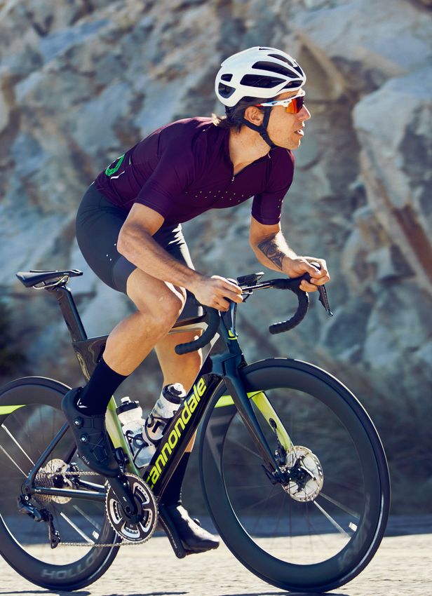
WHITE
PAPER
SYSTEMSIX

Table of Contents                                        Executive Summary
                                                         The all-new SystemSix is here. So are the test results. And we’re proud to
3     Executive Summary                                  say that this race-bred speed machine is absolutely the lowest-drag, most
                                                         efficient, all-around fastest UCI-legal road bike on the market today. Not only
4     Overview
                                                         the fastest in the wind tunnel. Not only the fastest for a select few riders in
5     Cycling Performance                                a select few scenarios, but the fastest for anyone interested in going faster,
                                                         just about everywhere you’d want to go faster. Call it drag reduction. Call it
14    Aerodynamics                                       aerodynamic advantage. We call it free speed, and it is the culmination of a
                                                         multi-year, systemwide approach to efficiency and real-world performance.
18    On Road Performance                                Proving just what can be accomplished when the entire machine - not just the
                                                         frame and fork - is optimized for fast. Delivering real speed for real riders.
27    Weight

28    Handling & Ride Character

30    Comfort & Ride Detail

32    SystemSix Details: Frame & Fork, Cockpit, Wheels

42    References

43    Glossary

Contributors:
Damon Rinard, Engineering Manager, Road Bikes
David Guzik, Vice President of Engineering
Denis Kuerner, Design Engineer, Components
Ian Hamilton, Managing Industrial Designer
Jonathan Schottler, Lead Design Engineer
Nathan Barry, Design Engineer, Aerodynamics

Prepared June 25, 2018                                                                                                                     3
Cycling Performance
                                                                             How do we determine cycling performance?
                                                                             Cycling performance can be described by a balance of
                                                                             input power against resistive forces. There are six resistive
                                                                             loads acting on a bicycle and rider system. These are:

                                                                                 •    Rolling resistance
                                                                                 •    Wheel bearing friction
                                                                                 •    Drivetrain friction
                                                                                 •    Aerodynamic drag
                                                                                 •    Potential energy – the energy you expend to climb
                                                                                 •    Kinetic energy – the energy you expend to accelerate

                                                                             These six terms are related by the cycling power equation.
                                                                             This is a scientifically validated equation derived by Martin
                                                                             et al. (1998) that describes the resistive power terms:

                                                                                  η . PAthlete = PNET = PAero + PRR + PWB + PPE + PKE

                                                                             Where;
                                                                                Aerodynamic Resistance:		                PAero = CD A 12 ρVA 2VR
    Overview                                                                    Rolling Resistance:			                   PRR = μ (mB + mR)g.cos (tan-1(G)) VR

    SystemSix was designed to be the fastest road bike on the planet.           Wheel Bearing Resistance:		              PWB = (91+ 8.7VG ).10 -3. VR
    This is a bike designed to deliver more speed, more of the time. This
                                                                                Resistance Due to Altitude Gain:         PPE = (mB+ mR)g.sin (tan-1(G)) VR
    is not just a bike for racers, but anyone who likes to go fast.
                                                                                                                                                         (VR 2 2 - VR 12)
                                                                                Resistance Due to Acceleration:          PKE =   1
                                                                                                                                     (mB + mR + 1r 2 )
    SystemSix is a complete bicycle system with each component                                                                   2                          (t2 - t1)

    optimized in pursuit of speed, without sacrificing any of that classic      Drivetrain Efficiency: 			               η
    race bike feel. SystemSix comprises six unique elements:
       •   Frame
       •   Fork
       •   Seatpost                                                          Using this equation, we can take a detailed look at the
                                                                             interaction between resistive loads in cycling. This gives us
       •   Stem
                                                                             a better understanding of how each element affects cycling
       •   Handlebar
                                                                             performance so we can work to minimize those that have
       •   Wheels
                                                                             the greatest influence. Note that the drivetrain efficiency
    When setting out to design a bike with the ultimate pursuit of           is represented by a single scaling factor, η, not a separate
    speed it is first important to understand what it is that makes a        term. This is because drivetrain efficiency is most commonly
    bike and rider fast. This all begins with the six elements of cycling    represented as a percentage of the input power.
    resistance – these are the resistive components that work against
    you as a rider. Minimizing these will make you faster for the same
4   effort, or allow you to maintain the same speed with less effort.                                                                                                       5
Speed and Power When shown as a percentage of total it is seen that
aerodynamic resistance is more than 50% of total
power at speeds above 15 km/h (~9 mph). This
Aerodynamic power is a cubic function of velocity (this
means that aerodynamic drag has a large impact
can be seen in the power equation on previous page).
on cycling performance at all levels. Remember
This means that aerodynamic power increases much
that 15 km/h is the cross over point. Below this,
more rapidly than the other resistive terms. This fact is
aerodynamic drag is still providing resistance on
now generally understood by the cycling community.
the bicycle and rider. Since aerodynamics is a
However, it is also the origin of a common misconception
function of velocity, as soon as you start moving,
that aerodynamics is only important at high speed.
aerodynamic drag is working against you.
As can be seen in Figure 1, aerodynamic resistance
increases its proportion of total resistance as your speed
This data is calculated using typical road cycling values
increases. But this is not to say that it is only important at
in the cycling power equation. In these examples we
some arbitrary high speed. A more useful approach is
are considering a flat road, so the Potential Energy
to consider aerodynamic resistance as a percentage of
(PE) term is zero. We are also considering steady
your total power as a rider. This is shown in Figure 2.
state riding (no acceleration) which means the
Kinetic Energy (KE) term is also zero. This is a general
assumption to look at the influence of other factors
but is a reasonable model for many cycling scenarios.
Input parameters for the equation are typical values
for a road rider and are listed in Appendix A.
It is worth making one more point on the influence of
aerodynamics on riders of differing speeds. It is still
sometimes quoted that aerodynamics only matters
above a certain speed and therefore aerodynamic
performance is only relevant to elite athletes. Consider
the power equation, the aerodynamic power term is a
Figure 1 – Cycling power breakdown with velocity. Figure 3a – Time saving for athletes of varying power cubic function of velocity. This means that for a given
levels over a 40km time trial given a drag reduction aerodynamic saving, a faster rider will have a larger
of 0.015m2. power saving. However, the opposite is true for time
savings. Because a slower athlete spends more time
on course, the equivalent drag saving actually results
in a larger time saving than for the faster athlete. For
example, consider a saving of 0.015 m2 and riders
completing a 40 km time trial. The power saving and
time saving over that event are plotted in Figures 3a
and 3b, using some typical input parameters for the
power equation. The data shows that while the less
powerful rider is slower, they save more time over a
fixed distance event. This further highlights how all
road riders can benefit from aerodynamic savings.
Figure 2 – Resistive elements proportion of total power with Figure 3b – Power saving for riders at different
increasing velocity. speeds given a drag reduction of 0.015 m2.
6 7The Influence of Gradient So far, we have looked at data for riding on a flat road with increasing velocity. The obvious question then is: what happens when we start climbing? Figure 4 applies the same approach as used earlier, and calculates power distribution for increasingly steep gradients. Each column in the graph represents the distribution of power at a given gradient. In this case we are considering a rider with a steady 300 watt output. It is intuitive to see that as gradient increases more of your power is spent overcoming the gradient (potential energy term). It also follows that your speed will drop as gradient increases. Since aerodynamic drag is a function of velocity (and not mass or gradient) this means that the aerodynamic power term also decreases. Looking closely you will also note that rolling resistance decreases, because power consumed by rolling resistance is a function of velocity: as speed drops on the climb, so does the corresponding power term. Figure 4 – Distribution of power across each resistive term with increasing gradient. The power equation shows us that the primary input in the potential energy term is mass. Gradient and speed are clearly important, but are a function of the road, not the part we have control over. So, the big questions is, which has the largest benefit in terms of performance; aerodynamics or mass? The equation shows us that, all things being equal, lower mass will always be preferable. But what about when things aren’t equal? Very rarely in design can you achieve the lightest weight without sacrificing some other area of performance. Similarly, typically optimizing for aerodynamics requires increased surface area as sections are shaped to better move through the air. This greater surface area usually means an increase in weight. It is, therefore, important to consider how weight and aerodynamic savings interplay on overall performance and ultimately speed. 9
The Tipping Point                                                    despite a higher weight, is in fact, faster up hill. This is a
                                                                          new concept for a lot of cyclists. It is also one of the key
                                                                          reasons SystemSix offers more speed more of the time.
     One of the most useful tools for assessing the interplay
     between weight and aerodynamic optimization is to look
                                                                          It is worth noting that 6% is quite a significant grade.
     at two possible configurations and determine the gradient
                                                                          Many of the grandest climbs in the European alps
     at which the weight saving become more beneficial to
                                                                          average a 7% grade. So when we consider SystemSix
     performance that the aerodynamic saving. On flat roads
                                                                          being faster on slopes up to 6%, it encompasses a very
     mass has very little impact and so aerodynamic savings
                                                                          large chunk of the terrain covered by most riders.
     will always have a greater impact on performance. As
     gradient increases we will reach a break even point
                                                                          This tipping point is affected by the mass and power of a
     at which the aerodynamic saving and weight saving
                                                                          rider. Higher power-to-weight ratio (for a stronger rider)
     provide equal performance. Only above this gradient is
                                                                          shifts the tipping point to a higher gradient. This is because
     a weight saving benefiting performance. Figure 5 below
                                                                          more power results in higher climbing speed and thus the
     compares SystemSix against a traditional lightweight
                                                                          influence of aerodynamics is more pronounced. For our
     race bike like the SuperSix EVO. For consistency this is
                                                                          professional riders that are climbing at and above 5 W/
     assuming the same wheels on both bikes. The difference
                                                                          kg the tipping point is closer to 7%. This effect is shown in
     is in weight and aerodynamics; SuperSix EVO is 1 kg
                                                                          Figure 6 below plotting tipping point against power-to-
     lighter* than SystemSix but suffers from 0.034 m2 greater
                                                                          weight ratio. The key takeaway from this is the fact that it
     aerodynamic drag. *1 kg weight difference is for a rim brake
                                                                          is actually possible to climb faster on a heavier bike than
     SuperSix EVO as ridden by our professional athletes.
                                                                          a light bike given sufficient aerodynamic improvement.

     Figure 5 – The tipping point between a modern lightweight bike       Figure 6 – Variation of tipping point with power-to-weight ratio.
     and SystemSix. Positive indicates time saved on SystemSix in s/km.

     Figure 5 shows a time saving, in seconds per kilometer,              This result is interesting when you consider the power
     for the SystemSix vs SuperSix EVO. The positive region               distribution shown in Figure 4 (page 8). You can see that
     indicates that SystemSix is faster than the modern                   at a gradient of 6%, the climbing power (PE term) is an
     lightweight race bike. The negative region is the reverse;           order of magnitude bigger than the aerodynamic power.
     the lighter bike has the upper hand. For example, at 0%              And yet, at 6% the performance is equal. The reason for
     gradient, SystemSix saves 3 s/km over SuperSix EVO, for              this is because climbing power is a function of total mass.
     this rider (4 W/kg). The horizontal intercept is the gradient        And for a bicycle, the rider has much greater mass than
     at which the two bikes are equal in performance. In Figure           the bike. Even a very large mass saving on the bicycle is
     5, the break-even point occurs at 6%, This means that on             relatively small overall. By contrast, aerodynamic savings,
     a 6% slope, you would be equally fast on either bike. Only           even on just the bike, excluding rider contributions,
     above 6% is there an advantage to riding the lighter weight          can be a much larger portion of the total system and
10   bike. This means that on slopes less than 6% SystemSix,              thus have a larger overall impact on performance.           11
The Place for Light Weight For most riders, the majority of ride time will be spent on roads with gradients less than this 6% tipping point. And for those more limited times when the gradient exceeds 6% it is worth considering what you sacrifice you are really making. Consider our rider at 4 W/kg on a 10% grade. At that power they are travelling at a little more than 12 km/h. At this speed the heavier SystemSix requires 2.7 watts more power to match speed with the lighter bike. It is worth asking, will that extra power make enough difference on the steep climb or is there more to gain on the rest of the ride with the huge savings at lower gradients and higher speeds? However, for some riders, like our GC contenders and climbers of EF Drapac p/b Cannondale, those >7% sections of big climbs might be the most important moment of the whole stage. When we work with these riders we look at their critical moment in the race. That point where they know they will be at and beyond their limit. This is where we need to optimize performance. For a big mountain stage with extended stretches above 7%, the lighter weight SuperSix EVO is an important weapon because those riders can’t afford to give away anything. But for the rest of us not tackling HC passes on a daily basis, the gains of the SystemSix up to 6% offer a big boost in performance, more of the time. 12 13
Aerodynamics
                                                                                                                                Obviously yaw angles are important, as we ride in varying
                                                                                                                                wind conditions on the road. And as evidenced by
                                                                                                                                Figure 7, aerodynamic performance can vary significantly
                                                                                                                                with yaw. While SystemSix is consistently lower, other
SystemSix Aerodynamic Performance                                                                                               competitors have lines that intersect, making it difficult
Aerodynamics is clearly a critical element in the performance                                                                   to analyze and pinpoint performance differences. To
of road bicycles. SystemSix was designed to have class                                                                          simplify the interpretation of this data and to incorporate
leading aerodynamic performance. A bold claim; one that                                                                         the real-world effects of yaw angle, we at Cannondale
we have proven through benchmarking our competitors.                                                                            use the method of Yaw Weighted Drag (Barry 2018).

Wind tunnel testing remains the most reliable method
for accurately measuring aerodynamic drag. We tested
SystemSix at the San Diego Low Speed Wind Tunnel
(LSWT) against the fastest bikes currently available in the
elite racing segment. Bicycles were tested as sold and
specified by the manufacturer. The drag of each bicycle is
plotted in Figure 7 on next page. Data is plotted as CDA,
normalized from drag measurements taken at 30 mph.
Error bars have been omitted from the graph for clarity.
Uncertainty in CDA is approximately ±0.0005m2. Full
details of bicycle builds can be found in Appendix F.

For a brief introduction to the fundamentals of
aerodynamic drag, units and CDA refer to Appendix B.

It is apparent from the figure that SystemSix has consistently
                                                                             0.12                                                                                              Classic Road BIke
lower drag compared to existing class leading road
racing bikes. The closest competitor on sale today to                                                                                                                          Scott Foil
                                                                             0.11
SystemSix in this test was the Trek Madone. Compared to
                                                                                                                                                                               Pinarell o Dogma
the Madone, SystemSix has an almost consistent offset
                                                                             0.10                                                                                              F10
in drag across the yaw range. The one exception to this                                                                                                                        Canyon Aeroad
trend is the Cervelo S5 which has the lowest drag in
                                                                             0.09
test at 20 yaw angle. Only at this single point does any                                                                                                                       Giant Propel
competitor present significantly lower drag than SystemSix.

                                                                 CDA (m2 )
                                                                             0.08                                                                                              Specialized Venge
We will discuss in the following section how this impacts                                                                                                                      Vias
overall performance and the significance of yaw angle.                                                                                                                         Cervelo S5
                                                                             0.07
                                                                                                                                                                               Felt AR
For comparison, Figure 7 also includes a classic road
                                                                             0.06
bike, modeled here by our SuperSix EVO with the same                                                                                                                           Trek Madone
matched wheelset. Differences would be far greater with
                                                                             0.05                                                                                              SystemSix
a traditional shallow wheelset. This shows a big difference                         -20      -15       -10       -5        0         5        10        15        20
between bikes that have been optimized for aerodynamic
performance, compared to modern lightweight designs                                                                    Yaw (deg)
with round tube sections. Even with an increased scale,
                                                                                    Figure 7 – Normalized drag (CDA) vs yaw angle of competitor bikes compared to SystemSix.
SystemSix can be seen to have significantly lower drag
than the current generation of low drag road bikes.

14                                                                                                                                                                                                 15
Yaw Weighted Drag Using yaw weighted drag, the comparison of aerodynamic
performance can be greatly simplified. It is now obvious that
SystemSix has the lowest drag of these high-performance
The variation of drag with yaw angle makes it a difficult
race bikes. As a unit of CDA* it is not immediately apparent
process to clearly state differences in aerodynamic drag,
what this means in terms of on road performance; this will
as seen in Figure 7. SystemSix consistently shows lower
be addressed in more detail in the following sections. As a
drag than competitors across the yaw range, but other
simple case we can look at the power required to overcome
curves intersect as drag varies with yaw angle. In assessing
air resistance. Figure 9 below shows the additional power
aerodynamic performance, we also need to consider that
required at 30 mph for each competitor bike compared to
all yaw angles are not equal when riding on the road.
SystemSix. Where SystemSix is the reference; positive values
indicate additional power required by that of the competitor.
Yaw angles seen by a rider or vehicle on the road have been
A modern road bike (SuperSix EVO) is included for reference.
measured and discussed by various sources including:
Cooper et al. 2003, Mavic, Trek, SwissSide, FLO Cycling.
From this we know that low yaw angles are significantly
more likely than high yaw angles with the distribution
Testing With and Without a Rider
following a general Gaussian or bell curve. However,
Wind tunnel data in this report is presented for bicycles
objectively combining the variation of drag with yaw angle
tested in isolation. This is the most controllable condition
with the probability of yaw angles is not agreed upon or
for testing of bicycles as it eliminates the instabilities
widely communicated in cycling. At Cannondale, we use
introduced by a rider, even a mannequin. It does have
a method called Yaw Weighted Drag (Barry 2018). This
its limitations, however, as testing without a rider does
methodology provides a statistical weighting function
not capture the true flow field around a bicycle. It will be
for yaw angle distribution that is used to weight drag
discussed later how SystemSix was developed and studied
measured in the wind tunnel. Taking the normalized
in simulations using a rider. However, it was not possible to
integral of this weighted curve provides a single value
replicate these conditions in the wind tunnel. This does not
called Yaw Weighted Drag and is denoted CDA*. Yaw
discount the wind tunnel results. Comparisons of testing
Weighted Drag condenses all the information contained in
and simulations show that the differences in drag from tests
Figure 7 (on previous page) combined with the statistical
with and without a rider tend to be of similar magnitude.
likelihood of yaw angles on the road. This makes analysis
Sample tests were conducted with SystemSix against
of aerodynamics much simpler as we can now plot CDA*
key competitors from above using a rider. While there is
as a column chart (see Figure 8). A deeper discussion
significant uncertainty in these results, they did confirm the
of Yaw Weighted Drag can be found in Appendix D.
trend seen in isolated bicycle testing as shown above and
show that SystemSix has lower drag than its competitors.
Figure 8 – Yaw weighted drag at 3.13 m/s Figure 9 – Difference in yaw weighted air power at 30 mph
wind speed, 40 km/h road speed. relative to SystemSix. Positive values indicate additional power
required above SystemSix from yaw weighted drag.On Road Performance Breakaways
There are many different scenarios that we could
While we can look at different individual metrics, the real
consider when looking at a breakaway. The first is
measure of performance is what these elements add up to as
sitting in the wind, either breaking away solo or pulling
a system on the road. This is how SystemSix was designed;
on the front of the group. On a flat road at 45 km/h
to maximize speed on the road. We model this by taking the
SystemSix saves over 40W compared to a modern race
various performance elements and feeding them back into
bike like SuperSix EVO. That is with the same deep race
the power equation and simulate various riding scenarios.
wheels on both bikes. That is a lot of energy if you are
The three key performance metrics for a bike are: CDA
planning on going off the front for any length of time.
– aerodynamic performance, CRR – tire rolling resistance
and mass. We then add in the gradient of a given road.
But what about drafting? This is an area of performance that
is often ignored because in the peloton riders are typically
From this point we can assess performance in two ways;
riding well below their limit. But if you consider any racing
either a power saving or a speed change. If we consider a
condition, riders in the peloton want to conserve as much
fixed velocity, you can evaluate the difference in power with
energy as possible, whether it is a breakaway where riders
a change in setup or equipment. Or we can flip that around
need to recover for their next turn at the front, a GC rider in
and use a fixed input power and look at how a rider’s speed
a stage race conserving energy for key stages or a sprinter
would change. From this you can then calculate a time saving
biding their time for the finale. Scientific literature has
over a given distance. This modeling process is where yaw
confirmed what we know from experience; drafting greatly
weighted drag becomes critical because it provides a single
reduces aerodynamic resistance. Riding in second position,
value that can be used as the aerodynamic component in
this drag reduction is of the order of 40% (Zdravkovich
the power equation. We will now look at some typical riding
et al. 1996, Barry et al. 2014) and potentially even greater
scenarios that highlight the performance of SystemSix
when in a large group. This scaling also applies to any
compared to a modern lightweight bike like SuperSix EVO.
aerodynamic savings. That means a saving of 24W @ 45 km/h
for SystemSix compared to a modern lightweight bike, even
Sprints when drafting. That is a lot of energy to save over the course
of a long day in the break, or even your local group ride.
Sprints are an obvious scenario where aerodynamic
optimization can have a big impact on performance. For a race scenario it is also important to consider what
The high speeds of a finale mean that aerodynamic drag this performance can mean in terms of time saving. At
strongly dominates over other resistive forces. But just how race speeds SystemSix saves 3 s/km over the modern
much difference can aerodynamic savings makes during race bike. This savings adds up significantly over the
a final kick from the bunch? Let’s compare SystemSix and course of a long breakaway. And it is really important
SuperSix EVO – the two primary weapons of EF Education when you consider the run in to the finish. Over the final
First Drapac p/b Cannondale. Consider the final kick with 10km of a stage that time saving means SystemSix would
the final 200m covered at an average speed of 60 km/h. get to the line 30 sec ahead of the modern lightweight
For a typical rider that 12s effort would require an average race bike. For a rider off the front trying to fend off the
of 1000W. Over this final kick the SystemSix would achieve charging peloton this could be the difference between
a 2.1 km/h top speed and reach the line 0.4 sec ahead of winning and being swallowed up in the final kilometer.
the modern race bike. That doesn’t sound like a big margin,
but at 60km/h that equates to 7.2m, or four bike lengths.
That is a huge difference over just the final 200m of a race.
Add to this the fact that SystemSix requires far less power
on the high speed run in to the finish, even when drafting.
18 19Descending Climbing
Descending can be an equally important part of cycling. The tipping point, as discussed previously, is the
The high speeds mean that a lot of distance can be gradient at which mass becomes more important than
gained, or lost. We generally can consider descending aerodynamics. This is a useful way to interpret climbing
performance under two conditions; rolling and pedaling. performance between two different setups, or bicycles.
This gradient is then easily applied to any given road
First, consider a rolling descent. Aerodynamic drag segment to assess time gain or loss. This was previously
is the key component in defining terminal velocity. A presented in "The Tipping Point" on page 10.
rider rolling down a 6% grade on SystemSix achieves a
terminal velocity of 63.6 km/h (~40 mph). A rider on a It is also worth putting numbers to how much power it
modern lightweight bike requires nearly an additional requires to carry any additional weight on a climb. Consider
130W power output just to keep up. Now let’s take a the same rider used in the Tipping Point example riding
steeper descent where riders are completely spun out either a SystemSix or a modern road bike like a SuperSix
and just rolling. For an 8% non-technical descent with no EVO. For a fixed 300W we can calculate the riders speed on
braking, SystemSix tops out at 74 km/h. The rider on the the modern road bike. If we consider that same rider, riding
modern lightweight bike is 5.4 km/h slower in this case. the same speed on SystemSix, how much power do they
Over a 1 km section of decent this is a time difference of save or lose depending on the gradient? We can answer
nearly 4 seconds or almost an 80m gap on the road. this in Figure 10 below. You can see that at low gradient and
high speed that the savings from SystemSix is signifcant.
Now let’s consider a racing scenario with a pedaling Nearly 30W at 0% and 40 km/h. As gradient increases,
descent. On a 5% grade at 200W, the rider on SystemSix approaching the tipping point, the savings reduce and
achieves 61 km/h. To match that speed on a lightweight then flip. Above the 6% tipping point the lighter bike has
climbing bike the same rider would require 310W. the advantage. But, as you can see, the savings are small.
This can be the difference between recovering on a Even at 10% grade, the 1kg lighter bike saves less than 3W,
descent versus pushing at the limit, just to keep pace. compared to the 29W saving of SystemSix on a flat road.
Figure 10 – Power saved riding SystemSix compared
to a modern lightweight road bike. Speed calculated
from typical rider values on the lightweight bike.
20 21Not Just For Racing
Racing provides some clear examples of the performance
benefits of SystemSix compared to a modern race bike
over a range of different scenarios. But SystemSix is
not just for elite racers and offers serious benefits to
riders of all levels. Take a cruising speed of 30 km/h (~18
mph) on a flat road; a comfortable cruising speed for
most road cyclists. Compared to a modern road bike
with low profile wheels, SystemSix would save that rider
approximately 17W just in aerodynamic resistance. This
pace equates to a savings of about 10% of your total
power. That is not an insignificant amount when you
consider a training ride of several hours. And as you ramp
this speed up for more spirited riding the savings only
increases. At 32 km/h it’s 20W. At 35 km/h it’s 26W.
22 23Acceleration Acceleration, much like climbing, is a function of
the total system mass. Thus, most of your energy is
expended to accelerate your body mass, with the
The analysis presented thus far has focused on steady
bicycle being secondary. A bicycle that weighs an
state conditions; no acceleration. While many scenarios in
extra 1 kg requires only an additional 3.5W additional
cycling, both racing and training, can be well considered
power to perform that 2 m/s2 acceleration. This is 1.3%
with negligible acceleration, this is not universally the case.
increase in power. For a 75 kg rider and a 7 kg bike, a 1
kg mass increase is a little over 1% of the total system
One of the key questions we get from those concerned
mass which is in proportion to the additional power.
with weight, is the effect on acceleration. This is a
common criticism of deeper section wheels posed by
When you consider the difference in mass for a wheelset,
climbers. If we consider the cycling power equation
it becomes clear that it has little impact on acceleration.
again we note that there is a term that accounts for
For a 100g increase in wheelset mass, at worst, only 0.7W
acceleration in the form of changing kinetic energy.
additional power would be required for this acceleration.
This accounts for both translational and rotational
(VR 2 2 - VR 12)
PKE = 1
(mB + mR + 1 2 ) acceleration, and assumes all rotational mass is concentrated
2 r (t2 - t1)
at the tire outer radius. Remember too that as you accelerate,
your aerodynamic resistance climbs rapidly. From 20
km/h to 25 km/h your aerodynamic power doubles. So
Consider accelerating from 20 km/h to 25 km/h in 2.5
even for an acceleration on a climb, as modeled here,
s – a powerful acceleration of 2 m/s2. This acceleration
there is little to no advantage of a lightweight wheelset.
would require 280W for our reference rider. Note that
this is independent of gradient. The gradient affects
Deeper wheels do have some differing handling
the potential energy term and so power required to
characteristics compared to their lighter, low profile
overcome the gradient will increase with velocity;
siblings. Out of plane torque, both additional rim mass
but that is independent of the acceleration itself. For
and aerodynamic resistance affects the roll of the bike;
example, on a 7% grade climb, riding at 25 km/h requires
how the bike feels as you lean it over. Whilst this can feel
an additional 74W compared to riding at 20 km/h.
different on a deeper wheel, this feeling is in the lateral
plane of the bike. This has little to no effect on the forward
motion of the bike, which is what dictates speed.
24 25Weight
Whilst weight plays a secondary role to aerodynamics in
most riding scenarios, there is no need to lug around more
bike than you need. All things being equal, less weight is
always a good thing. To minimize the weight of SystemSix
without sacrificing stiffness, we used Hi-MOD carbon fiber
as the primary material throughout the frame. This is one
of the highest performing types of carbon fiber available,
and the highest grade of carbon that Cannondale (and
most of the cycling industry) has utilized to date. The use of
such high-performance materials enables us to have larger
surface area on the frame, for minimizing aerodynamic
drag, without a significant weight penalty. Figure 11 shows
the bonded frame weight for SystemSix Hi-MOD. The
bonded weight is the raw manufactured weight before
paint and small parts. Small parts add up to 65g. Paint
adds a further ~70g depending on the paint scheme.
Figure 11 – Frame bonded weight for SystemSix Hi-MOD.
Bonded weight does not include paint or small parts.
26 27Handling and Ride Stiffness
Character The stiffness of a bike is important in the feel and
responsiveness of the frame, both to steering inputs and
putting the power down through the pedals. SystemSix
The responsiveness and handling of a bike are was developed to match the head tube (HT) and bottom
driven by geometry and stiffness. Any race bike from bracket (BB) stiffness benchmark set by our proven SuperSix
Cannondale needs to have that confidence inspiring EVO. Stiffness is optimized per size for ideal handling for
steering response and stiffness that are trademarks all rider sizes. Taller riders, on average, are stronger and
of our SuperSix EVO and other models. heavier than lighter riders, and the longer frame tubes of
larger frames can often mean that larger frames are less
From inception, SystemSix was developed around the race still than small frames. Ideally HT stiffness should increase
proven steering geometry of our elite race platform. Two with frame size. Figure 13 shows the frame stiffness across
different fork offsets (45 and 55mm) are used to provide the size range of SystemSix. You can see that HT stiffness
consistent feel and handling across the range and ensures that generally increases with frame size and sits above the
the ride experience for smaller riders is not compromised. ideal for all sizes. BB stiffness is constant across the size
run, consistently exceeding our ideal target. Both Hi-
Geometry MOD and carbon frames have the same stiffness. They
are also geometrically identical. The only difference is
SystemSix comes with our elite race stack and reach. This the layup, which results in the slight weight increase of
allows riders to adopt an aggressive long and low posture. the carbon frame compared to the Hi-MOD (140g).
However, with adjustable cockpit and spacers, SystemSix
is for every day riders as much as it is for the racer.
B
O
F
Q
N
75mm
A
E
D C
L
J I H
K
G M
47 51 54 56 58 60 62
A SEAT TUBE LENGTH (CM) 38.5 43.3 48.2 53 55.3 57.7 60
B TOP TUBE HORIZONTAL (CM) 51.4 52.9 54.4 56 57.6 59.2 60.9
C HEAD TUBE ANGLE 71.2° * 73.0° * * 72.9° *
D SEAT TUBE ANGLE 75.1° 74.7° 74.3° 73.9° 73.5° 73.1° 72.7°
E STANDOVER (CM) 68 72.3 76.2 79.8 82.1 84.3 86.3
F HEAD TUBE LENGTH (CM) 8.8 11.4 12.8 14.9 17.2 19.3 21.4
G WHEELBASE (CM) 97.4 98.9 97.5 98.7 100 101.2 102.4
H FRONT CENTER (CM) 58.2 59.5 58.1 59.3 60.5 61.7 62.9
I CHAIN STAY LENGTH (CM) 40.5 * * * * * *
J BOTTOM BRACKET DROP (CM) 7.9 7.4 7.2 * 6.9 * *
K BOTTOM BRACKET HEIGHT (CM) 26.1 26.6 26.9 * 27.1 * *
L FORK RAKE (CM) 5.5 * 4.5 * * * *
Figure 13 – Head tube (HT) and bottom bracket (BB)
M TRAIL (CM) 5.8 * 5.7 * * 5.8 *
N STACK (CM) 50 52 54 56 58 60 62 stiffness for all frame sizes of SystemSix.
O REACH (CM) 37.5 38.1 38.6 39.2 39.8 40.3 40.9
Figure 12 – Geometry chart. 29Comfort and Ride Feel
Comfort and ride feel are an important element of
any bicycle. In conceptualizing SystemSix we wanted
to ensure that we could deliver the maximum gains in
speed without sacrificing the feel of our modern race
bikes. When we consider the comfort of a bicycle, we are
really talking about compliance; the vertical stiffness.
The bicycle system is comprised of many components
that connect the rider to the road; tires, wheels, frame,
seat post and saddle. Each of these elements has their
own stiffness that contributes to the overall stiffness of
the bicycle system. Whilst the frame and fork can have
an influence on this, for rigid frames, it is the tire that
typically has the greatest impact on compliance. And
we know that tire stiffness is driven by tire pressure.
Herein lies the advantage of larger tires. Using a larger
volume tire gives you more height which allows you to
run lower pressures without bottoming out the rim.
In conceiving SystemSix this led us to create a bike that
would have world leading aerodynamics with a larger
tire than is traditionally found on race bikes. Many of the
current generation of race bikes are still optimized around
a small volume tire, especially when presenting wind tunnel
data, where small tires outperform larger tires. We have
seen this in our own testing and has also been reported
by FLO Cycling amongst others. SystemSix bucks this
trend by starting with a minimum 26mm measured tire.
By using a larger tire a rider can run lower pressure for a
more supple ride, improved road feel and comfort, without
sacrificing any aerodynamic performance. We will look at
the design details of the wheel in the coming sections.
For a detailed discussion of tire mechanics we recommend
you take a look at the work of Silca; https://silca.cc/blogs/
30 31SystemSix Details
Truncated airfoil sections can be seen throughout the
SystemSix frame, fork, SP, and handlebar. A truncated airfoil
simply refers to an airfoil section that has had a portion
There is little doubt of the important role that aerodynamics of the tail chopped off rather than finishing at a sharp
plays in the performance for all road cyclists, not just trailing edge. However, the point at which the airfoil is
racers. With this knowledge reinforced, we set out to truncated from the initial airfoil shape, means that truncated
minimize the aerodynamic drag on all elements of the airfoils represent a large family of profiles with potentially
bike. By taking a holistic view of the bicycle system very different aerodynamic properties. Each tube on
we came to incorporate the frame, fork, seat post, SystemSix received a unique profile specifically selected
handlebar, stem and wheels. In developing SystemSix for optimum performance in the local flow conditions.
we broke the bike down into 3 aerodynamic zones: Figure 15 – Airfoil with sharp trailing edge (black) and
It is worth noting that for attached airflow, a truncated airfoil
truncated airfoil created from same airfoil (blue).
1. Front wheel, fork, HT, DT, TT will always have higher drag than a complete airfoil with a
2. ST, SP, BB long tail. The low drag of an airfoil stems from minimizing
3. SS, CS, rear wheel the pressure drag that arises from a separated wake and
resulting low pressure region behind the body. On an
Aerodynamics were optimized using both computational airfoil the tail allows the flow over the upper and lower
fluid dynamics (CFD) and wind tunnel testing. These surfaces to recombine with negligible wake. By truncating
two techniques are complimentary and best results will an airfoil, by definition, you remove this characteristic and
always come when combining the two. CFD simulations introduce intended separation and thus a wake. However, by
in zone 2 and 3, and on full bike models, were conducted carefully designing the profile and the amount of truncation
with a rider model on the bike to ensure a realistic it is possible to minimize the increase in pressure drag
flow field. This shows that some areas of the bike are but remove some of the length of the airfoil. When done
heavily influenced by the presence of the rider such as correctly it is possible to introduce a small drag penalty
the seat post. Wind tunnel testing was used to validate but large reduction in perimeter, which saves weight.
the design and to benchmark competitors as this is the
most accurate measure of aerodynamic performance. SystemSix was designed to ensure that flow remained
Figure 16 – (Top) Flow around a truncated airfoil with
attached along the full length of the tubes and to maintain
correct tail gradient with flow attachment along full
length of body. (Bottom) Flow around a profile with too that attachment as late as possible in yaw. It has been shown
steep tail gradient leading to early flow separation. that low yaw angles are always more prevalent than high
yaw angles (Cooper 2003, Mavic, Trek, FLO, SwissSide) with
the distribution generally following a Gaussian or bell curve.
By keeping flow attached with a fixed separation point we
minimize drag at the important low yaw angles, rather than
focussing on high yaw and post stall performance, which
has much less impact on overall performance. The critical
parameter for flow attachment is the curvature of the tube
beyond the point of maximum thickness. If the curvature,
or gradient, of the tail is too sharp, the flow will separate in
the adverse pressure gradient. Separated flow then leads
to a large wake and large pressure drag on the body.
Figure 14 – Computational fluid dynamics
(CFD) simulation of SystemSix with rider
32 33Frame & Fork The chine on the downtube is a unique characteristic of
the SystemSix that serves a specific aerodynamic purpose.
Due to the rake of the fork leg there is a pocket of flow that
The specific tube shapes used on SystemSix are also
runs up the back of the fork leg towards the fork crown.
dictated by the strict rules of the UCI. The critical one being
The chine redirects this flow and channels it downstream,
the collection of 80mm boxes that dictate the maximum
preventing it from continuing upwards and interfering with
depth of the tubes. The UCI rule states that the main tubes
the clean flow over the fork crown and headtube above.
of a bicycle must be no less than 25mm and no deeper
Above the chine there is one continuous airfoil profile that
than 80mm. To understand the implications, consider an
encompasses the fork crown, head tube and down tube.
airfoil which is a slender body. Typically an airfoil has a
This ensures clean flow over the entire fork crown region.
thickness that is < 30% of the length. For a 25mm wide
tube this would make the length 83mm. This means that
any true airfoil will need to be truncated in order to meet
the UCI rules. When you consider larger tubes, like a head
tube that needs to house bearings, then the required width
of the airfoil is larger. This means the full length of that
airfoil also increases dramatically. In order to preserve the
gradient on the tail, you end up with a large truncation for
such tubes, similar to what you see on the SystemSix head
tube. It is this attention to the shape of individual regions
on the SystemSix to ensure flow attachment that leads
to the differences you see between frame elements.
Figure 18– Flow moving up the fork crown is redirected
The unique wide shape of the fork crown, head tube and downstream by the chine.
down tube junction arises from our zoned design approach.
The front of the bike was designed with the frame and fork Creating a bike that could fully conceal brake lines was an
as a single piece. It was only after we were satisfied with the important consideration during the SystemSix development
performance were they separated into two separate pieces. process. We wanted to achieve a fully integrated system
To this end the whole fork crown region utilizes a continuous but with a design that was still easy for dealers and riders
airfoil section across the fork, HT and DT. This ensures clean to service. From the outset we agreed that the brake lines
flow across the front of the bike rather than breaking it up would not pass through the head set bearings and that it
between a disconnected fork and frame. This is also aided by should be possible to adjust stack without disconnecting
the disc only design which removes a rim brake caliper from any cables or hoses. The result is a design that routes
the fork crown that would normally disrupt the clean free cables through an enclosed channel in front of the head
stream flow that hits this part of the bike. Eliminating a rim tube, bypassing headset bearings and the fork steerer. The
brake caliper also allows riders to fit tires up to 30mm wide. head tube incorporates a separate carbon liner sleeve that
protects the cables from contacting the steerer. The trade off
to the ease-of-use design is that the steering angle needs to
be limited so that excess steering angle cannot be applied
and damage the brake hoses. Therefore, the steering on
SystemSix is limited to ± 50°. Through extensive ride testing
we determined that this is a far greater steering angle than
is typically required when riding. In fact, you typically use
less than 30° while riding as most steering is done through
leaning. Only when performing low speed maneuvers or
track standing will you ever feel the limit of the steering,
even if you do notice it when wheeling the bike around.
34 Figure 17 – A cross section of continuous airfoil over the fork crown. 35Cockpit bar tops use an airfoil section with a large
truncation and gradual taper. This is relatively
HollowGram KNØT64 For this reason, many race bikes and wheels
are still tested in wind tunnels with small tires.
The KNØT SystemBar and Stem is a unique
insensitive to pitch angle and ensures flow Wheelset However, it is not widely reported what is
remains attached at all positions. Therefore, sacrificed in performance when replaced with
setup designed specifically for SystemSix. It The HollowGram KNØT64 wheel was the
the drag penalty from personalizing your larger rubber. From the outset, we started with
provides the integration of a one-piece bar starting point for the entire SystemSix project.
bar position is negligible. The bar cross a large tire and designed a rim around a larger
and stem but retains the fit and adjustability Since the front wheel is the leading edge of
section has large radii on the trailing edge profile that could still meet our strict aerodynamic
of a two-piece system. The cockpit, especially the whole bicycle it sees the cleanest airflow.
for better ergonomics, but without sacrificing performance requirements. The result is a unique
the handlebar, has a profound impact on Therefore, it was is an important starting point
aerodynamic performance. If more comfort is rim profile with an outer width of 32mm. This was
the drag of the bicycle system and so it for aerodynamic optimization. The objective
desired then the bar tops can be wrapped with only possible by committing to a disc brake only
is an important element of performance. with the KNØT64 wheel was to design a wheel
a relatively small aerodynamic penalty. Our platform for both the SystemSix and the KNØT64
However, a cockpit is central to fit and that would achieve low drag even when fitted
wind tunnel testing showed that fully wrapping wheel. As well as being wide on the outside, it
rider comfort on the bike. Herein lies the with a minimum 26mm tire. Larger tires have
the bars, like a traditional round bar, only adds is also wide on the inside at 21mm. This means
advantage of an integrated two-piece setup. many benefits for ride feel and comfort, but
0.001 m2 drag; < 1W at 40 km/h (~25 mph). that tires grow to much larger than their named
typically sacrifice aerodynamic performance. size when mounted on this rim. For example, a
The KNØT SystemBar comes in four widths: 38,
The KNØT stem comes in a range of lengths 23C Vittoria Rubino Pro Speed tire measures
40, 42 and 44cm. Every size bar has a 30mm When considering wheel aerodynamics, it is
to allow riders to dial in their fit: 80, 90, 100, ~26mm* on the KNØT64 rim. The 25C version of
flair from the hoods to the end of the drops. important to remember that the wheel and tire
110 and 120mm. The stem is an open c-section the same tire measures ~28mm. That’s a big tire
A size 42cm bar measures 40cm at the hoods are a coupled system. For the leading half of the
design that cradles the handlebar and permits on a race bike. And the shape of the rim means
and widens 30mm at the end of the drops wheel, the tire is the leading edge and thus has a
easy assembly. The lower cover then snaps into that you can run a 28mm tire with minimal increase
(center-to-center). This narrower than standard strong impact on the aerodynamic performance
place once all the cables are in place. This is in drag compared to a smaller 26mm tire.
hood position is designed to further help the of the wheel. As the leading edge, the tire tends
coupled with a split-hinge spacer design that
rider maximise their speed. Narrower hand to control the separation from the leeside of
allows a spacer to be added or removed without To optimize performance of the wheel system
positions reduce frontal area and can help the rim and thus drives the stall characteristics
disconnecting hydraulic hoses or shift housing. (rim + tire) we have licensed technology
reduce drag on the rider, while maintaining of the wheel. This not only affects the wheel from HED to spec the fastest possible
width in the drops for stability when needed. but can be seen in the drag of the entire bike. tire. HED Cycling Products, Inc. Patent
When we consider a tire that is as wide, or wider US8888195 B1 allows a wheel designer to
The bar and stem interface permits 8° of than the rim, the flow tends to separate from predict and design in a particular stall angle
pitch adjustment in the handlebar. The the tire and is not able to reattach to the leeside to a wheel based on the tangent angle
of the rim in yawed flow. This leads to a wide between the rim edge and tire, and having
wake and high pressure drag (see Figure 19). a fast wheel at the desired yaw angle(s).
In contrast, the wide rim profile of the KNØT64
allows the flow from a wider tire to reattach The KNØT64 wheelset also includes a
to the rim cleanly and thus reduce drag. bespoke front hub with a smaller hub shell to
minimize frontal area. At only 23mm diameter
the hub is significantly smaller than many
contemporary disc brake wheelsets.
HollowGram KNØT64 Wheelset
Rim Max Outer Width 32 mm
Rim Bead Width 21 mm
Figure 19 - (Top) Flow profile around the KNØT64 rim with Spoke Count (F/R) 20/24
its extra wide rim profile. Flow remains attached to the Weight (F/R) 765/877 g
leeside of the rim at yaw, even with a wide tire. (Bottom)
Flow around a wheel where rim and tire are of equivalent
width. Flow separates from tire without reattaching *Manufacturing variation means that actual tire size can vary between individual
samples of the same tire model.
to rim leading to wider wake and higher drag.KNØT64 Aerodynamics Wheel Performance Against
Competitors
Effect of Tires on Wheel The HollowGram KNØT64 wheels were tested at the San
Performance Diego Low Speed Wind Tunnel (LSWT) against a selection of
high performance road wheels. As discussed previously, tires
Tires have a profound influence on the drag of a wheel. have a profound impact on the aerodynamic performance
Figure 20 shows the KNØT64 rim tested with a range of a wheel. To normalize the test all wheels were tested
of different tires, all similar width. Drag at low yaw is with Continental Grand Prix 4000S II tires. Tires were
tightly grouped with only small differences between chosen based on measured size, rather than named size,
tires. But at higher yaw angles the effect of tires on stall as variation in rim bead width greatly affects the physical
is pronounced; note the magnitude of difference at 15° size of the tire on the rim. And for a given tire, the width
yaw angle. The stall of the wheel is not only connected is the important variable to normalize, rather than the
with the width of the tire but also the construction method labeled size. The normalized drag (CDA) vs yaw angle are
and tread profile. The fact that the biggest differences plotted in Figure 21. All competitor wheels were rim brake
occur at high yaw angles also highlights the value of yaw configuration. Disc brake wheels are generally considered
weighted drag in evaluating on road performance. to have performance secondary to rim brakes. To avoid
Figure 20 – KNØT64 rim tested with any bias towards the KNØT64 being disc brake only we
Our approach to wheels and tires is consistent with the a range of different tires.
selected competitors high-performance rim brake wheels.
whole SystemSix project; focused on speed. As we identified The Hed Jet was tested with both 23C and 25C tires as it
earlier, performance is not just about aerodynamics. has the same wide 21mm internal width as the KNØT64.
This is especially true for wheels and tires as we must
consider both the aerodynamic performance and the In this form the results are somewhat difficult to interpret
rolling resistance of a tire. A tire that tests well in the wind as the intersecting lines make it unclear which has
tunnel may have high rolling resistance that nullifies any the best aerodynamic performance. Figure 22 below
aerodynamic benefit. Similarly, a low rolling resistance tire shows the yaw weighted drag of each wheel in this test
might be compromised by poor aerodynamics. We analyze to simplify the analysis and eliminate the ambiguity of
performance using the power model taking yaw weighted variation with yaw. Note that the 25C has only marginally
drag from the wind tunnel and combining with the rolling higher drag than the 23C tire. On the KNØT64 this
resistance of each tire to model on road power differences. 25C tire measures 28mm, showing that you can run
From this we can then determine the fastest combination. large tires with minimal sacrifice in performance.
There are several public sources for rolling resistance data
available, including conducting your own testing at home.
Figure 21 – Normalized drag (C DA) of KNØT64
We find bicyclerollingresistance.com a great resource for wheel and competitors.
comparing the performance of a large range of road tires.
SystemSix comes with Vittoria Rubino Pro Speed tires
which were selected due to their balance of low drag
and low rolling resistance. The Corsa G+ is another high-
performance tire from Vittoria but is hand-made, whereas
the Rubino is vulcanised. The two tires are manufactured
from identical compounds which leads to very similar rolling
resistance. However, handmade tires like the Corsa generally
have a significant aerodynamic penalty. Overall performance Figure 22 – Yaw Weighted Drag (C DA*) of KNØT64 wheel and
therefore favors the Rubino Pro Speed. Just another area competitors. Wind speed 3.13 m/s, road speed 25 mph.
where SystemSix delivers more speed to more riders.
39Wheel Testing Seat Post
At this point the more critical reader would ask; how does The SystemSix seat post features a unique cross section
testing a wheel in isolation relate to performance on the matched to its local flow conditions to ensure flow
bike? This is a very good question. On the bike the leading attachment and to minimize drag. This follows the design
half of the rim may see clean flow, but even the back half of the rest of the bike, utilizing an airfoil section with a
of the front wheel is surrounded by fork legs, the down truncated tail. The seat post is an important contributor to
tube and even the rider's feet. The rear wheel is in the the drag of the bike as it is an exposed element, despite
wake of nearly every other element. So does wheel testing being well downstream of the leading edge, and even with
in isolation provide us with useful information? Yes. the presence of a rider. In fact, the legs of a rider accelerate
the flow over the seat post to be greater than the road speed
The data on the previous page shows that drag, in particular of the bike. Higher local velocity means that the drag force
the stall point, is strongly influenced by the tire. This is is also higher; recall the equation of aerodynamic drag
driven by the separation of the flow from the wheel and (see Appendix B). The rider's legs in proximity to the seat
tire. In practice, the wheel and tire are a system and their post create a contraction that accelerates the flow between
performance is closely linked. The wrong tire can ruin the the legs and then over the seat post. In this case, testing
performance of the best wheel; for example, using a tire without a rider reduces the relative contribution of the seat
that is far too big. The leading edge of the wheel, and post as it would see flow at freestream velocity, not faster.
indeed the whole bike, is the tire. The interaction between This can be demonstrated by looking at velocity planes
the wheel and tire dictates whether the flow can reattach in CFD. Figure 23 shows a color contour of velocity on a
to the rim after separating from the tire. This drives the stall horizontal plane through the seat post. White regions are
point observed in the drag plot and correlates strongly freestream velocity – the speed of the air around the bike.
with the stall characteristic of the entire bicycle. Since Yellow regions indicate flow faster than freestream, blue
the leading half of the wheel, where this phenomenon indicates regions where the flow speed is below freestream.
occurs sees such clean flow, wheel performance on a bike
correlates well to the results of isolated wheel testing. The presence of a rider’s legs also introduces local yaw
angles, depending on instantaneous position. This means
that the post can see local yaw angles differing to that of the
bike and rider system. The highly truncated airfoil profile and
very gradual taper ratio ensure that flow remains attached
Rider's left leg
even in the presence of these induced local yaw angles.
Rider's right leg
Figure 23 – Horizontal plane of velocity contour from computational
fluid dynamics showing the accelerated flow between the rider’s
legs and over the seat post. Yellow/orange regions indicate flow
velocity above freestream whereas blue indicates below freestream.
40 41References Glossary
Barry N, Burton D, Sheridan J and Brown, NAT, 2014, The effect of spatial PAthlete Input power from the rider.
position on the aerodynamic interactions between cyclists, Procedia
PNET Net power.
Engineering, 72, p 774-779, DOI:10.1016/j.proeng.2014.06.131
PAero Power due to aerodynamic drag.
Barry N, Burton D, Sheridan J and Brown, NAT, 2014,
Aerodynamic performance and riding posture in road cycling and PRR Power due to rolling resistance.
triathlon, Proc. IMech, Part P: Journal of Sports Engineering and PWB Power due to wheel bearing friction.
Technology, https://doi.org/10.1177/1754337114549876
PPE Power due to potential energy gain. This is
Barry N, 2018, A new method for analysing the effect of environmental the power it takes to climb a hill.
wind on real world aerodynamic performance in cycling, PKE Power due to kinetic energy. This is the power it takes to accelerate.
Proceedings MDPI, 2(211), doi:10.3390/proceedings2060211
CDA The product of the coefficient of drag (CD) and the
Cooper KR, 2003, Truck Aerodynamics Reborn – Lessons from the Past, SAE frontal area (A). This is a normalized form of drag
Technical Paper Series 2003-01-3376, Society of Automotive Engineers, USA removing the fluid dependent properties.
ρ Air density.
Crouch TN, Burton D, Brown NAT, Thompson MC and Sheridan J, 2014,
Flow topology in the wake of a cyclist and its effect on aerodynamic drag, VA Air velocity.
Journal of Fluid Mechanics, 748, p 5-35, DOI:10.1017/jfm.2013.678 VR Road velocity.
Flo Cycling. Available online: www.flocycling.com/ µ Coefficient of rolling resistance of tyres.
aero.php (accessed on 1 June 2016).
mB Bike mass.
Martin JC, Douglas ML, Cobb JE, McFadden KL and Coggan mR Rider mass.
AR, 1998, Validation of a mathematical model for road cycling
power, Journal of Applied Biomechanics, 14, p 276-291 g Gravitational acceleration.
G Gradient.
Mavic. Available online: http://engineerstalk.mavic.
com/en/ (accessed on 1 June 2016). η Mechanical efficiency (%).
Chord The length of an airfoil from its leading edge to the trailing edge.
Silca. Available online: https://silca.cc/blogs/journal (accessed 1 June 2017)
Flare For handlebars; describes the increase in width
Swiss Side. Available online: https://www.swissside.com/blogs/news/ from the hoods to the end of the drops.
the-swiss-side-instrumented-bike (accessed on 1 June 2016).
Frontal Area The silhouette area of on object when viewed from the front.
Commonly used as a reference area in aerodynamics.
Trek Bicycle Corp., The All-New Speed Concept. Available
online: www.trekbikes.com (accessed on 1 April 2015). Leeside The surface of a body that faces downstream as opposed
to the windward side which faces upstream.
Zdravkovich MM, Ashcroft MW, Chisholm SJ and Hicks N, 1996, Effect Yaw Angle The angle between the resultant air vector and
of Cyclist’s Posture and Vicinity of Another Cyclist on Aerodynamic direction of travel. Different from the wind angle due
Drag, The Engineering of Sport 1, Balkerna, Rotterdam to the vector sum of wind and road velocity.
42 43You can also read