Incorporation of Research and Novel Teaching Ideas into the Unit 'Surf equipment, design, materials and construction' - Curtin ...
←
→
Page content transcription
If your browser does not render page correctly, please read the page content below
Incorporation of Research and Novel Teaching Ideas into the Unit
         ‘Surf equipment, design, materials and construction’

                             Audy J.* & K., and Haines T.

Edith Cowan University
School of Enterprise and Technology
Faculty of Regional Professional Studies
South West Campus Bunbury
Australia 6230
E-mail (*Corresponding author): j.audy@ecu.edu.au

Dr. Jaromir AUDY is a Lecturer in Materials Science in the Surf Science and
Technology at Edith Cowan University. His professional experience is in design,
development of prototypes and testing, analyses of ferrous, nonferrous materials,
composites and testing, and production methods such as laminating, casting, forming,
forging, machining. Teaching and Research interests include: materials involved in
surfing, boating and automotive industry, optimisation of manufacturing methods using
data banks and computer assisted predictions.

Dr. Katarina AUDY is an active researcher and lecturer, currently working on two
teaching and learning grants at Edith Cowan University. Her professional experience is
in materials, testing, manufacturing processes, and data analysing. Research interest
includes: reconstruction and restoration of historical buildings and ancient artefacts,
archaeological metallurgy, and corrosion and degradation of materials.

Mr. Terry HAINES, formerly the Head of School of Enterprise and Technology, is
Acting Associate Dean (Teaching and Learning), Lecturer in IT and computer science,
and a full time employee of Edith Cowan University. Terry’s background is in
computers, modelling and data analysing.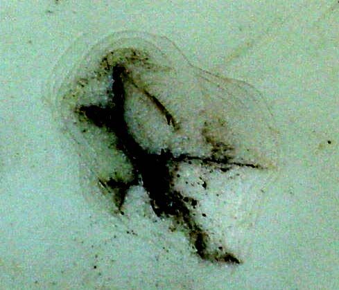
Incorporation of Research and Novel Teaching Ideas into the Unit
           ‘Surf equipment, design, materials and construction’

Abstract: There are four aspects of this paper which deal with the “Theoretic Underpinning of
Innovative Practices in Teaching, Learning and Research” within the Surf Science and Technology
Program at ECU. These are Experimentation and Testing on Real-Life Damages of Surfing Equipment,
Improvisation, Individuality of Learning environment, and Dissemination of results and conclusions.
Experimentation and testing was conducted on real-life damage of surf equipment. Improvisation was
necessary due to limited resources and lack of access to commercial professional testing equipment.
Students had to think laterally to make use of available resources to create testing situation where were
both reliable and accurate. Individual Teaching and Learning Environment involved a number of damage
surf boards that were obtained from commercial surf board manufacturers and/or individuals. Students
selected a damaged surf board and had to devise a test and facility to carry out experiments from available
resources. Although these units were taught there was no focus on testing the real surfboards the results
and conclusions have remained within the unit. In 2004 the students were able to use their own results
and the results of other students and incorporate these results into the design and manufacture of their
own surfboard within other units taken concurrently with the unit. This is the first stage of dissemination
of results. Moreover, for the first time this semester the teaching was focussed on examining flexural and
impact behaviour of various surfboard construction panels and appears to be successful from both
teaching and research point of view. Because in this relatively new academic discipline there are limited
relevant professional journals specifically related to Surf Science and Technology this paper is one way of
disseminating the results and conclusions to a wider audience.

Keywords: Surfboards, Breaking Mechanism, Failure, Laminates, Polyurethane Foams

1.     Surfboard Materials and Breaking Modes: An Introduction

Commercial surfboards are made from lightweight sandwich structures [1 to 5]. These
structures are made of a core laminated in fibreglass [1 to 3]. The core is made of
polyurethane foam strengthened in the middle with a wooden stringer to improve
stiffness [1 and 4]. The polyurethane foam is a soft and light weight material [1 to 5].
Its density is low ~40kg/m3 [3]. This means that the blanks used for shaping the
surfboards are very light [1 and 4]. Their masses vary from about 2.5 kg for small
blanks to about 4.5 kg for large blanks [1 and 4]. After shaping they lose ~30% of their
volume and when laminated the dry area weight of fibreglass is some of ~200g/m2 [3].

In seeking improved surfboard performance, the surfboard manufacturers and users
made significant advances through the modifications of surfboard geometry [1 to 4] and
the use of advanced materials [1 to 4] for sandwich panels [3] and laminates [3]
employed in surfboard construction. Most recent developments in the surfboard
industry relate to the decrease in surfboard weight [1 to 5] by reducing the thickness of
both the polyurethane cores for boards [1, 4 and 5] and polyester resin / E-glass woven
fabric for laminate skins [1, 4 and 5]. As a result these minimum weight and thickness
boards have a limited service life time [5] due to their inability to deal with impact
damage from waves. Moreover, they suffer severe cosmetic problems [2], caused by
impact damage from the human body and rocks. Some most common types of damage
are documented in Figure 1 (a to d). Figure 1 (a) shows smooth compression dents from
various human body parts typically the head and knees. Further details in Figure 1
depict: jagged cuts (b), compression cuts (c) and scratches (d) as a result of impact with
rocks.

The types of damage from rocks are particularly unpleasant because they tear the
laminate and damage the foam, see Figure 1 (b), or create cracks, see Figure 1 (c) and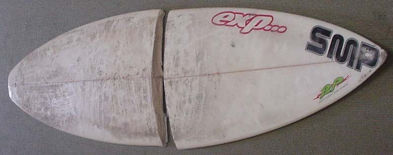
(d), through which the salt water is able to penetrate and cause delamination of the
laminate from the polyurethane foam.
(a) (b)
(c) (d)
Figure 1 Photographs showing several types of damage on surfboards caused by
the head and knees (a) and rocks (b to d).
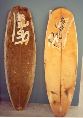
Typical damage from delamination is shown in Figure 2 (a to d). The photographs were
taken from a surfboard that was found lying on a beach and donated for research
purposes by one of our surf science student. Figure 2 (a) depicts the surfboard in ‘as
found’ condition. Figure 2 (b) shows the extent of damages (holes in the laminate)
around the fins. Figure 2 (c) shows the nose that was once broken, cut, rounded and not
professionally laminated. Because of this salt water was allowed to penetrate though
the holes, scratches and cavities, causing a complete delamination of the laminate and
damage of the polyurethane foam as shown in Figure 2 (d).
(a) (b)
Figure 2 Photographs showing an old fashioned surfboard that was left abandoned
on a beach (a), damage of laminate around the fins (b), and laminate
stripped from polyurethane foam – bottom side (c), and deck (d).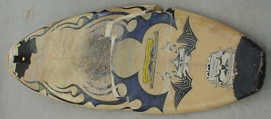
(c)                                         (d)
      foam, left, laminate skin, right             foam, left, laminate skin, right
                     Figure 2        Continued from previous page

The damages shown earlier in Figures 1 and 2 affect both the appearance and material
properties but the surfboards can still be used. The most severe bending damage to
surfboards occurs as a result of collisions with the wave. Table 1 shows a set of
photographs and relevant details associated with breaking damage of four different
commercial surfboards (A to D). The first three boards (A to C) were short ones (6’0’’
and 6’1’’ in length) and quite light ones (weighing less than 3kg). They all were new
and purchased for more than $400 and less than $500. Board D was long (6’6’’ in
length), weighed 3.8kg with fins, and being old was purchased for about $80. Board A
had its nose broken when it dived into the sand. Boards B and D snapped under
bending impact from a wave. Board C snapped when the surfer hit a reef. The age of
these boards apparently did not play a significant role in life reduction since board B
was only 3 months old when snapped by a wave when floating on water.

Table 1    Photographs showing fatal damage of four different commercial surfboards,
           left, and their relevant details, right.

                                                            (A) 6’0’’ x 18 1/4’’ x 2 1/4’’
                                                           by Green Deluxe (~$400 new)
                                                             weight without fins 2.8kg
                                                              about 2 years old when
                                                            damaged by the nose diving
                                                                   into the sand
                                                             used daily (2 times a day)
                                                            (B) 6’1’’ x 18 3/8’’ x 2 1/4’’
                                                             by Damien BIBIC (~$430
                                                                   brand new)
                                                            weight with FCS fins 3.1kg
                                                             about 3 months old when
                                                             damaged by a wave when
                                                                floating on water
                                                             used daily (2 times a day)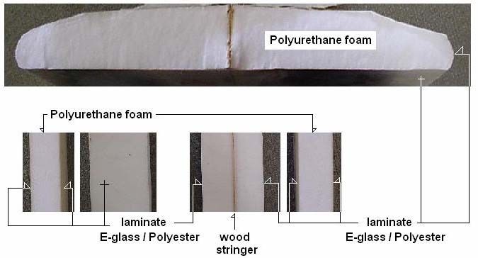
Table 1       Continued from previous page

                                                            (C) 6’1’’ x 18 3/4’’ x 2 3/16’’
                                                            by Boyd Purdy YALLINGUP
                                                                 (~$500 brand new)
                                                              weight without fins 2.4 kg
                                                             6 months old when snapped.
                                                            Nose hit a reef and the board
                                                           snapped under the weight of the
                                                                        surfer
                                                            (D) 6’6’’ x 18 1/2’’ x 2 3/8’’
                                                                  by Dale Chapman
                                                               weight with fins 3.8 kg
                                                              Very old Board (~1990)
                                                            (purchased for ~$80, about 2
                                                                     years ago)
                                                           Used occasionally, Snapped by
                                                                      a wave

The observation of these surfboards illustrated in Table 1 indicated that the failure was
probably initiated by the wrinkling on the side of the board that was actually under
compression when hit by a wave. Board C, for example, exhibited significant wrinkling
on its bottom side which was its compression side when the board was flexed by the
weight of a surfer standing on its tail after the nose hit the reef. Figure 3 shows two
photographs: the one on the left picturing a surfboard with compression wrinkles across
the laminate, and the one on the right picturing a section of a surfboard that snapped
under flexural bending.

Figure 3    Photographs showing compression wrinkles across the laminate on the
            bottom side of a surfboard, left, and clear snapped failure due to flexural
            bending impact.

An inspection of broken surfboards indicated that they failed by compression of the
foam core induced by localised wrinkling of the laminate due to bending and / or impact
load. This observation is in agreement with experimental results published by Manning
et al in paper [2] who suggested that it is possible to study the flexural behaviour of a
surfboard using the four point bend test, (described in source [6]), which is able to
produce stresses similar to that experienced in reality.

To date little information has been published on sandwich construction panels [1 to 3
and 7 to 9] and their breaking mechanism in terms of flexural bending and impact
behaviour. The reported information in source [1] was mostly descriptive and only a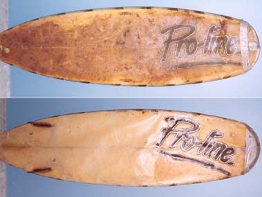
few sources [2 and 3] provided very limited data needed for quantitative study of
surfboards as a whole. Consequently, the present investigations were set up to study, in
laboratory conditions, flexural bending of sandwich panels and impact damage of
laminates in order to get the results similar to those exhibited by surfboards broken in
service conditions.

In terms of pedagogy the students were able to make use of real damaged surfboards
and employ problem solving techniques to determine laboratory tests that would be both
reliable and valid. Since there were a variety of surfboards with different damage the
students were required to individually determine a valid and reliable test. Moreover,
their own results and those of other students were applied during the design and
manufacture of their own surfboard. Each student designed and manufactured his or her
own surfboard and / or a body board in another unit done concurrently lectured by the
same lecturer.

The following experiments were a part of laboratory work conducted by the first year
surf science students in the second semester of 2004. The group of students was quite
small. It consisted of 14 people, namely 5 males and 9 females. Two students were
international (one from England, one from the United States), while the other twelve
students were Australians. The majority of students (~80%) came from 'small' country
towns, whereas others (20%) were either from private or top government High Schools.

Those students who lived in the country where technology and education were not at an
advanced stage in comparison to larger cities found it difficult to adapt to University
requirements in terms of bridging the differences between the study load at High
Schools and University. Most of the 'regional' students experienced major difficulties
of understanding the basic mathematical terms and equations. Because of this, the
majority of such students find it hard to understand technical terminology and scientific
approaches used in lectures and tutorials associated with 'Surf Equipment, Design,
Materials and Construction' courses.

During lectures and tutorials some students tended to be quiet, probably due to the fear
of being judged by their 'more skilled' colleagues, and it appeared that even with the
lecture notes and literature materials, they still had difficulty in understanding the topic
in greater detail. From experience it has been recognised that there is a need to improve
lecturer/student communication, to encourage interaction within the class, to improve
students' self-confidence and method of teaching and learning styles for better
understanding of the subject. With those aims in mind the laboratory experiments were
designed to address the following attributes: professional knowledge; workplace
experience, enterprise; initiative and creativity; service; problem solving/decision
making; internationalisation / crosscultural awareness and communication. The major
focus was on conceptualising the material delivered in class rooms and providing a link
between theory and practice. It was done by simplifying the lecture material to simpler
cases and linking them to students’ personal experiences. This approach provided a
number of samples and case studies for assisting the SST students to realize how to
apply theory to real life situations.

2.     Experimental Details

For the purpose of this investigation five specimens were studied, namely, (1) surfboard
C and (2) surfboard D shown earlier in Table 1, (3) non reinforced and non laminated
polyurethane foam, (4) polyurethane foam core with a single layer of laminate on deck
and bottom, and (5) polyurethane foam core reinforced with plywood stringer and
laminated on deck and bottom. Laminated specimens (2 and 3) had a 190 gsm cloth
with the fibre orientation of 90 degrees. Surfboards A and B were in reparable
conditions and as such were not selected for destructive tests. The specimens used for
testing represented different sections of a surfboard as depicted in Figure 4.

        Figure 4       Experimental details associated with the test specimens.

Experimental work was focussed on static (3-point bend) and dynamic (impact) tests.
The relevant test arrangement, results and discussion are presented in the following
Section 3.

3.     Test Arrangement, Results and Discussion

Each laboratory experiment described in sub-Sections 3.1 to 3.3 was designed for the
duration of approximately 3 hours. This time limit was set up for preparing the relevant
test scenario, conducting experiments and gathering results. It was anticipated that
some students with limited hands-on skill and working experience may have a difficulty
to transfer theoretical knowledge into practical life. To overcome this problem the
students were asked to work in groups. They formed five groups (3 people in a group).

During the laboratory demonstrations students tended to be quite active and inquired
about many issues they were uncertain about. Students firstly shared their knowledge
together in groups then compared it between the groups. It appeared that there was
something like 'an impulsive' competition between the groups in terms of being the first
and getting the most reliable results. The role of the lecturer during these sessions was
to communicate with the students, help them with the test arrangement, check the
results, and most importantly, to provide advice on data analysis, its evaluation and the
write-up of the scientific reports. From experience it was recognised that the majority
of students lacked the skill in writing technical reports. Those students were in their
early course. They were very reluctant to be critical and had a tendency to be
descriptive rather than quantitative. The lecturer’s role at this stage was very crucial
and an extra consultation time (of ~2 hours per person) was dedicated to go over
assignment drafts.

The experimental work, data collection and evaluation were quite straight forward.
Students had to follow instructions given to them during the lecture time, and work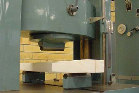
under supervision of the experienced demonstrator. Some short insides of these kinds
related to different tests are briefly shown in the following sub-Sections 3.1 to 3.3.

3. 1    3-point bend Test of a Polyurethane Foam Specimen

Students were encouraged to cut a piece of new surfboard foam, sand it to make a
rectangular prism, weigh it and record its dimensions, and calculate its density using
Equation 1.

                  Mass[kg ]
ρ[kg / m 3 ] =                                                                         (1)
                 Volume[m 3 ]

Table 2 provides an example of some typical results obtained from this exercise. From
this table it is evident that the calculated density of experimental polyurethane foam was
about 41 kg/m3, which was similar to the foam density of 40.9 kg/m3 (st dev=3.5, dof 6)
reported for a Type EW219725 polyurethane blank in paper [3].

Table 2     Dimensional, Mass and Density Data associated with experimental
            polyurethane foam tested.

  Thickness            Width        Length         Mass        Volume          Density
   t (mm)              b (mm)       l (mm)          (g)        (mm2)          ρ (kg/m3)
       25                   40        350          14.5        350000           41.4

After that students constructed a 3-point bend test apparatus from available materials,
and for different loads recorded the deflection of foam specimens. A schematic 3-point
bend test and the real experimental arrangement are shown in Figure 5 (a) and (b),
respectively.

                      (a)                                             (b)

Figure 5 Experimental set up for 3-point bend test, left, and the real arrangement,
         right.

As can be seen from Figure 5 the materials used were from those available, namely,
PVC pipes, plastic bag(s) filled up with dry sand to provide the desired weight(s), and
tables apart by about 200mm allowing for separation of support of 270mm. This test
can be repeated and will produce reliable and valid results. This is an example of
students being subjected to an individual learning environment and using problem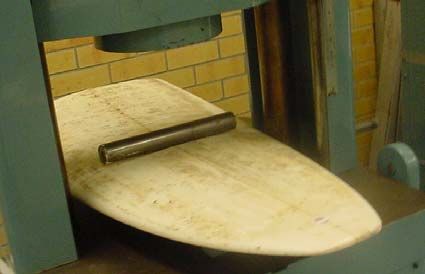
solving skills to determine the laboratory test. Five groups of students (three people in
each group) repeated the test to prove its reliability.

An example of experimental plot of load versus deflection for the foam data, Table 2,
and set-up, Figure 5, is shown in Figure 6.

                      (a)                                               (b)

Figure 6            Experimental plots of load versus deflection data for polyurethane foam
                    prism from Table 2.

From Figure 6 (a) it is evident that the load deflection graph exhibits an elastic region
and a plastic region. From data in the elastic region, it was possible to calculate the
Young Modulus of Elasticity, E. For a rectangular specimen of a width, b, a thickness,
t, and a length, l, which is deflected to a distance, y, by the applied force, F, over the
separation of support, L, the Elastic Modulus, E, is given by Equation 2.

    F L3
E=                                                                                     (2)
   4 y b t3

The Equation 2 can be rewritten into Equation 3 that uses the slope of the graph in its
linear region. This slope can be determined by using regression analysis and excel
software. From Figure 6 (b) it is evident that this slope was 1.66 and regression
analysis proved that this slope was statistically significant (Pcalculated=0.00024,
Fcalculated=153, dof = 5).

             L3
E   =             × slope of graph (in N/mm)                                           (3)
           4 b t3
From data in plastic region it was possible to determine the load at failure and to
calculate the bending strength, R, using Equation 4.

           3 FF L
R   =                                                                                  (4)
           2b t2

The experimental values were about 12.5 [MPa] for Modulus of Elasticity, E, and about
0.54 [MPa] for bending strength, R. It may be interesting to note that Wang and Crosky
[3] reported that the strength of polyurethane foams may vary by a factor of 2 with
respect to variation in cell size of the foam. This would result in having a thinner and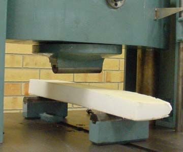
stronger panel with better flexural strength and improved ability to deal with elastic
stresses from a laminate during head or knee impact. Manning et al [2] suggested that
the stiffness would be enhanced further by using multiple stringers in surfboard foams.

3. 2   3-point bending Test of Laminated Polyurethane Foams and Surfboards

The flexural 3 point bend tests were carried out using Model AVERY universal testing
machine Type 711CCJ located at South West Regional College of TAFE.

This was a rare opportunity for students to see and use prominent testing equipment
with experiments directly relevant to surfboards thereby exposing the students to real
life of research thinking and industrial testing.

The experimental set up was as follows:

• The span length was 546mm.

• The radius of rollers was 19mm.

• Laminated specimens were flat parallel faced panels. Their length, width and
  thickness were 600mm, 115mm and 55mm, respectively. Surfboard C was 56mm
  thick and 470mm wide. Surfboard D was 51mm thick and 445mm wide.

The experimental test arrangement is shown in Figure 7(a to d). The results are shown
in Table 3.

  (a) Laminated un-reinforced PU foam         (b) Laminated wood reinforced PU foam

             (c) Surfboard C                              (d) Surfboard D

              Figure 7         3 point bend Experimental test arrangement
Table 3 Results from 3 point bend test
Displaceme
Load at
Specimen nt at peak Note
peak [N]
[mm]
Did not break - failed by
Laminated un-
delamination of laminate and
reinforced PU 650 16
compression of the core
foam
Bending strength R = 1.5MPa
Did not break – failed by
Laminated
delamination of laminate and
plywood reinforced 1830 20.9
compression of core
PU foam
Bending strength R = 4.3MPa
Load at break =1700N
Surfboard C 2100 22.8
Displacement at break = 35.9mm
Did not break – failed by
Surfboard D 2700 31.9 delamination of laminate and
compression of core
From the results in Table 3 it is evident that the experimental specimens and surfboards
failed at loads of between 0.65 kN and 2.7 kN, which is roughly equivalent to weights
between 65 kg and 270 kg.
The polyurethane foam strengthened with a plywood stringer had a bending strength
greater by a factor of 2.8 (=4.3/1.5) compared to the non reinforced specimen. Manning
et al [2] reported that the panel which has its core reinforced with much lighter balsa
stringer improved an increase in the strength only by about 60% compared to an un-
reinforced panel.
Laminated plywood reinforced PU foam specimen was made from recent surfboard
blank and its load at peak (1.8kN) and displacement to peak (20.9mm) were identical to
those (2.1kN and 22.8mm) obtained from the recent surfboard C. In contrast, surfboard
D was about 15 years old and it exhibited more favourable both the load at peak that
was higher by a factor of 1.3 (=2.7/2.1) and displacement at break that was higher by a
factor of 1.4 (=31.9/22.8) compared to data from surfboard C. This indicates that each
surfboard has to be treated individually from material and damage point of view when
estimating its material properties and behaviour under stress.
3. 3 Impact Testing of Laminated Specimens and Surfboards
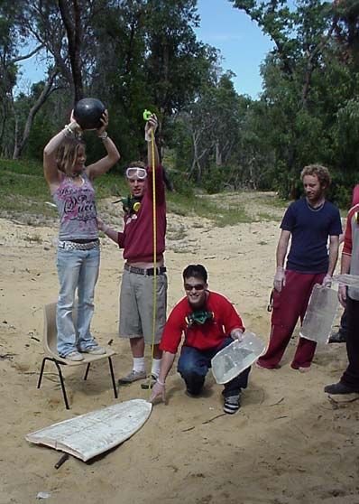
Experimental testing involved the four specimens listed earlier in Table 3. The exercise
was carried out by dropping the 7 kg heavy bowling ball from the heights of 1 metre
and 2 metres to the surface of each experimental specimen, as shown in Figure 8.
After that students were encouraged to estimate the extent of impact damage to laminate
and foam via the measurement of diameter and / or the depth of compression dents.
Again we see students improvising to produce laboratory testing conditions that are able
to be repeated producing identical results to make a valid and reliable test scenario.Figure 8 Some of the 2nd year surf science and technology students involved in
impact testing of laminated specimens (Semester 2, 2004)
Generally, two types of compression dents occurred, namely, circular and non circular.
Circular dents that reassembled fully the shape of the impact ball were quite rare. In the
majority of cases, however, the hole offprints were not symmetrical, mostly because of
the delamination of laminate from the compressed foam.
The diameter of the circular compression dents, d, was a function of the diameter of the
impact ball, D and the depth of the hole, x, as shown in Equation 5.
d = 2. D 2 − (D − x )
2
(5)
Whenever the offprints from impact ball were not circular the area, A, was calculated
from the ‘measured’ and ‘calculated’ values of the diameter of the hole, d1 and d2, see
Equation 6.
π
A = d1 d 2 (6)
4
For a symmetrical hole offprints their relevant volume, V, was calculated using
Equation 7.
⎛ x3 ⎞
V = π ⎜⎜ D.x 2 − ⎟⎟ (7)
⎝ 3 ⎠
For a non-symmetrical hole offprints their “approximate” volume, V*, was calculated
using Equation 8.π
V* = .d1.d 2 .x (8)
4
Generally, it was assumed that the volume of a dent would represent the work done by
the impact ball to damage the specimen. This assumption was based on the following
Equations 9 to 15.
Kinetic energy KE[ J ] = M IB .g.H D (9)
where MIB is the mass of an impact ball, HD is the drop height, and g (=9.81ms-2) is the
acceleration due to gravity [10]. Consequently, stress can be calculated from a kinetic
energy divided by dent volume.
KE
Stress σ= (10)
V
Volume V = A.x (11)
Work W = F .x (12)
F
Stress and Force σ= ⇒ F = σ .A (13)
A
From Equations 12 and 13
F .x = σ . A.x (14)
Then the Work W = σ .V (15)
The most important results from impact testing done at two different drop heights of 1m
and 2m are depicted in Figure 9. This figure shows the percentage differences in impact
energy of different experimental specimens with respect to the laminated but
unreinforced specimen which was taken as etalon for comparison purposes. From
Figure 9, left, it is evident that at the drop height of 1m the laminated but non reinforced
parts of surfboards C and D behaved similarly as the etalon specimen ie showed only
marginal improvement in impact resistance, namely by 5% for surfboard C and 10% for
surfboard D. The same specimens ,C and D, when tested at the drop height of 2 metres
showed marginal difference in impact energy by about 3% between themselves but
significant improvement in impact resistance by about 25% compared to the etalon
specimen. A similar qualitative trend was observed from Figure 9, right, which related
to the laminated wood reinforced specimens. Differences in impact energy between
surfboards were marginal with slightly better impact resistance of surfboard D against
surfboard C. Comparison of impact resistance of laminated non reinforced parts of
specimens C and D, Figure 9 left, and laminated wood reinforced parts of specimens C
and D, Figure 9 right, showed on average of about 20% difference in impact strength ,
for example the improvement which was contributed to the wood reinforcement. It
should be noted that both surfboards C and D were frequently used and some of the
damage could be contributed to wear and delamination. This probably affected the
impact strength of these structures, because the benefit of using wood stringer for
specimens that were not exposed to water eg laminated non reinforced etalon and
laminated wood reinforced specimen was much greater; about 33%.Figure 9 A histogram showing the experimental qualitative and quantitative trend in
impact energy of laminated non reinforced specimens and laminated wood
reinforced specimens tested with a 7kg heavy ball dropped from two
different heights of 1 m and 2 m.
Numerous useful observations and conclusions, both qualitative and quantitative in
nature, have been reached as a result of those strategies described in sub-Sections 3.1 to
3.3. An incorporation of the science and maths content into the classroom content
appeared to have a positive response from students because it resulted in better
understanding of materials and design in surf science that lead to improvements in their
own boards.
4. Conclusions
Conclusions that can be drawn from this study are summarised as follows:
The authors were granted a "Teaching and Learning" grant which was used to obtain a
variety of testing specimens, materials and relatively low cost measurement equipment
in order to expose the students to real life testing conditions.
The students responded well and enthusiastically to the laboratory scenario because:
1. they were using real-life damaged surfboards
2. they had to create their own tests from limited resources
3. they were able to use their results and those of other students to improve the
design of the surfboard they were making in another unit.
Analysis of broken surfboards showed that there are several possibilities responsible for
different failure modes. Majority of boards failed by compression of the core after
having one side of laminate under tension forcing laminate to yield to failure either due
brittle fracture after extending the fracture strength and/or by ductile failure when
extending the yield strength. These results indicated that various types of breaking
mechanism that occur in surfboards during normal service conditions can be simulated
by laboratory tests that were described in detail in sub-Sections 3.1 to 3.3. Thesestraight forward experiments appear to be well suited for laboratory work needed for
Surf Science Technology Program. The results showed that the strength of a core can
be increased by a wooden stringer so it may be interesting to study effects of several
stringers on strength and stiffness of PU foams. It would be also worth to explore the
effects of different resins and cloth of flexural and impact properties of sandwich panels
for surfboard industry.
d) The authors will continue in their teaching approach and research work, and intend to
publish the results in scientific / engineering peer reviewed journals.
REFERENCES
1. Orbelian G.: “Essential Surfing”, 3rd Edition, Orbelian Arts, IBSN 0-9610548-2-4,
San Francisco, June 1987.
2. Manning J.A., Crosky A.G. and Bandyopadhyay S.: “Flexural and Impact
Properties of Sandwich Panels Used in Surfboard Construction”, Advanced
Composites 93, edited by Chandra T. and Dhingra A.K., Minerals, Metals and
Materials Society 1993, pp213 to 126.
3. Wang J.Q. and Crosky A.G.: “Strengthening of Thin Skinned Foam Cored
Sandwich Panels”, The Institute of Metals and materials Australasia Ltd, (The
Materials Society of the IE Aust), Materials Research 96, Conference Proceedings
Volume1, Brisbane, Australia, Wednesday 10th July, 1996, pp. 132 to 135.
4. Haines T., Audy J. & K. and Killen P.: “Incorporation of Novel Ideas into ‘Surf
Equipment, Design, Materials and Construction’ Course”, Conference on “New
Challenges for Sustainability and Growth in Higher Education”, Khon Kaen,
Thailand, November 2004.
5. Audy J. & K. and Hatton E.: “Exploring New Tools for Open Learning in
Qualitative Education and Research Associated with Surf Science and
Technology”, The 5th Qualitative Research Conference, Bournemouth, UK,
September 2004.
6. ASTM D 6272-02, Standard Test Method for Flexural Properties of Unreinforced
and Reinforced Plastics and Electrical Insulating Materials by Four-Point Bending.
7. Weissman B. D.: “Marine Sandwich Structures Part II”, SAMPE Journal, 28,
(1992) 9.
8. Lingard J.R.: “Development of a Theory for Optimising Sandwich Composites”
Advanced Composites 93, Chandra T. and Dhingra A.K., eds, (1993) 259.
9. Marshal A.C.: “Core Composite and Sandwich Structures”, International
Encyclopedia of Composites, Lee S.M., ed., VCH (1991) 488.
10. Crowe C.T., Elger D.F. and Robertson J.A.: "Engineering Fluid Mechanics" 7th
Edition, J. Wiley and Sons Inc., ISBN 0-471-38482-8, USA, 2001, p. 10.
Acknowledgement
The authors would like to thank Mr. Ron Freckelton from South West Regional College
of TAFE for operating testing machinery when carrying out the flexural 3 point bend
test experiments described in sub-Section 3.2.
The authors would also like to thank the ECU for providing the "Teaching and
Learning" grant which allowed the purchase of testing specimens.You can also read