Installation guide for cars
←
→
Page content transcription
If your browser does not render page correctly, please read the page content below
Installation guide for cars

     Volkswagen
     Audi
     Seat
     Skoda

     1.9 TDI (Pumpe Düse)
     2.0 TDI (Pumpe Düse)

     55 kW / 75 hp
     62 kW / 84 hp
     63 kW / 86 hp
     66 kW / 90 hp

     74 kW / 101 hp
     75 kW / 102 hp
     77 kW / 105 hp
     85 kW / 115 hp
     96 kW / 130 hp

     103 kW / 140 hp
     110 kW / 150 hp
     118 kW / 160 hp

                              Version1.2 ‐14.11.2008‐ENG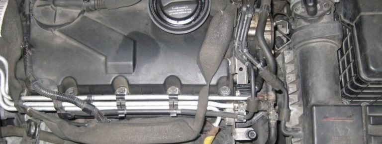
Installation guide for cars

General instructions
            Read this installation guide carefully before starting the installation
            so that you will be able to use all the technical advantages of the
            systems and do not start with the installation before you have read
            and understood the instructions.
            Your tuning system was designed and manufactured with great care and therefore should
            be also handled with care. If you comply with the advice given below you will avoid an
            early termination of the product guarantee and you will be enjoying your product for years
            to come.

            Never install the system if the ignition is on. Pull the ignition key. After switching off the
            ignition, wait for 5 minutes until all electric devices are turned off.

                                                                                                                                     5 MIN.

                 Please absolutely consider these references.     Ignition switch off .          Wait after switching the ignition off 5 min.

            If possible, install the module in a dry area in the engine compartment. Humidity and wetness
            contain minerals which cause corrosion to the electronic circuits. Fix the harness and protect it
            from humidity. Before every engine wash, remove the entire tuning system.

                          Install splash‐proof                  Attention with engine washing.            No installation on hot engine parts.

            Do not fix tuning systems to engine parts that could heat up. Never fix the module directly or close
            to the engine (engine block). High temperatures can reduce the lifespan of electronic devices and
            can deform
                d f      or melt
                              l specific
                                    ifi plastics
                                         l i materials.
                                                      i l

            Take care that the harness does not touch the parts in motion and the metal parts to avoid friction.
            Do not make any changes to the harness (do not make it any longer or shorter).

            In case of the malfunctioning of the system due to any non‐compliance with the instructions during
            the installation of the tuning modules, the product guarantee will be terminated.

                                                                               2                                                                 Version1.2 ‐14.11.2008‐ENG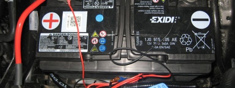
Installation guide for cars

      VW / Audi / Seat / Skoda 1.9 – 2.0 TDI
Installation
Switch off the ignition of the vehicle and remove the engine           After the calibration the module is compatible with the engine
cover. Localise the PD contact plug.                                   and requires no more settings. The vehicle is now ready for a
                                                                       test drive.
TIP! The original plug is with along built‐in engines at the end
of the cylinder head, near the splashing wall, with crosswise          The Performance tuning can obtain a different result
built‐in engines on the right side. To unlock the connection           throughout the series. It`s possible that the engine power
you have to pull off the red pin.                                      turns out to be too high or too low.

Connect the red cable with the plus pole of the battery.               If the power should be too high, it is shown by a strong soot
Connect the black cable with the minus pole of the battery.
                                                                       generation, disturbed engine run, engine misfire or the
Connect the PD module with the adapter cable.  cable Run the           initiation of the engine emergency program. Description on
calibration of the PD module (Description on page 10).                 the page fine tuning PD System.

                                                                       If you still have questions or you are not quite sure?
                                                                       Contact us, a technician will gladly help you!

PD System installation principle

      cable to motor control unit           PD adapter cable

            PD module         battery connection                                               engine

                                                                   3                                                    Version1.2 ‐14.11.2008‐ENG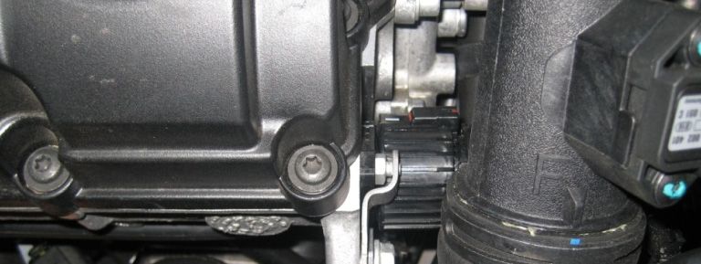
Installation guide for cars
VW / Audi / Seat / Skoda 1.9 – 2.0 TDI
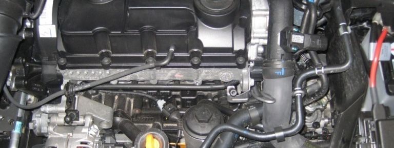
Installation example VW Golf V 1.9 TDI 105 hp
Open the engine hood.
Remove the engine cover (D). It is not screwed.
D
The engine is crosswise built in.
The PD plug (P) is located on the right side on the engine.
P
Localise the PD plug (P).
P
4 Version1.2 ‐14.11.2008‐ENG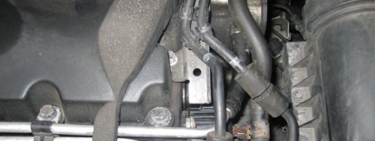
Installation guide for cars

    VW / Audi / Seat / Skoda 1.9 – 2.0 TDI
Installation example Audi A4 1.9 TDI 130 hp

                                              Open the engine hood.

                                              Remove the 3 cover caps (C1 – C3) and solve the engine
                     D
                                              cover screws. Remove the engine cover (D).
                              C3
            C1

                         C2

                                              The engine is along built in.
                                              The PD plug (P) is located behind the engine.

                 P

                                                 5                                            Version1.2 ‐14.11.2008‐ENG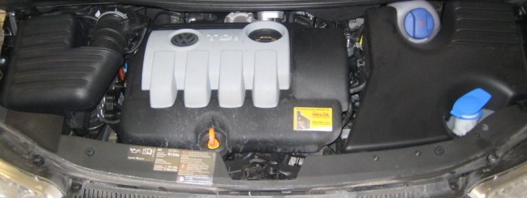
Installation guide for cars

    VW / Audi / Seat / Skoda 1.9 – 2.0 TDI
Installation example VW Sharan 2.0 TDI 140 hp

                                             Open the engine hood.
                                             Remove the engine cover (D). It is not screwed.

                 D

                                             The engine is crosswise built in.
                                             The PD plug (P) is located on the right side on the engine.

                            P

                                             Localise the PD plug (P).

                        P

                                                6                                              Version1.2 ‐14.11.2008‐ENG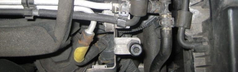
Installation guide for cars

    VW / Audi / Seat / Skoda 1.9 – 2.0 TDI
Installation PD plug

                                             Note the white lines on the original plug.

                                             To unlock the connection you have to pull out the red pin (S).

                               S

                                             Turn the plug counter‐clockwise until the white lines are
                                             coincides. The plug locks in this position.

                           S

                                                7                                            Version1.2 ‐14.11.2008‐ENG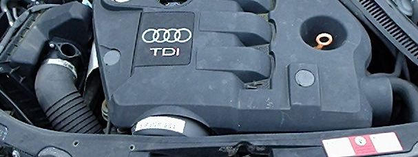
Installation guide for cars

    VW / Audi / Seat / Skoda 1.9 – 2.0 TDI
Installation PD plug

                                             Note the pin assignment from the plug. Connect the
                                             female plug on the same way.

                                             Connect the adapter cable plug. Note the white lines.

                                             Turn the plug clockwise to the top until it locks in the correct
                                             position.

                                                8                                              Version1.2 ‐14.11.2008‐ENG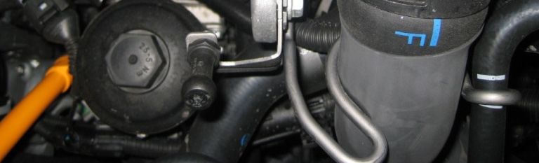
Installation guide for cars

      VW / Audi / Seat / Skoda 1.9 – 2.0 TDI
 Installation PD plug

                                               Connect the original plug from the car with the other side
                                               from the adapter cable. Note the white lines.

                                               Turn the original plug clockwise until it locks in the correct
                                               position.

PD connection

                PD female plug                         PD male plug

                                                  9                                              Version1.2 ‐14.11.2008‐ENG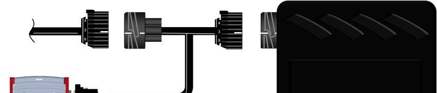
Installation guide for cars

          VW / Audi / Seat / Skoda 1.9 – 2.0 TDI
power supply

                                                             Connect the red cable with the plus pole of the battery.
                                                             Connect the black cable with the minus pole of the battery.

                                                             Move the adapterp      cable not in p parallel with injection
                                                                                                                   j
                                                             pipelines or ABS‐control device connecting leads. Keep to
                                                             very big distances. Fix the cable harness with cable binders.
                                                             Connect the CRD module with the adapter cable.

                                                             The module should be obstructed possibly against warmth
                                                             and splash water protected. Use the provided splash water
                                                             protection bag and fasten this by means of the velcro
                                                             fastening.

Calibration PD module

                                                            You have
                                                                  h    to calibrate
                                                                              lb       the
                                                                                        h moduled l nonrecurring before
                                                                                                                     b f     the
                                                                                                                              h
Calibration procedure                                       main installation. Connect the adapter cable. You can drive
                                                            with the connected adapter cable and without the module.
LED red      LED yellow
                                                            Bring the vehicle on operating temperature. Approx. 90°C
off         off             PD module is off
                                                            engine temperature are required to carry out a correct
on          off             PD module is on and read data   calibration. If the calibration is carried out in a cold engine, the
on          on (blinking)   PD module is calibrated         system does not function perfectly. The vehicle smokes very
                                                            strongly and it comes as a worried engine run. Switch off the
                                                            ignition and install the PD module.

                                                            Start the engine and do not press the accelerator! The
                                                            calibration phase needs at least 45sek in the tick‐over.

                                                            As long as the LED
                                                                           LED'ss (red and yellow) flash alternately.
                                                                                                         alternately The PD
                                                            module calibrates itself automatically. The calibration phase
                                                            ends if the both LEDs flashes. Now the system is ready for the
                                                            test run.

                                                               10                                               Version1.2 ‐14.11.2008‐ENG
Installation guide for cars
VW / Audi / Seat / Skoda 1.9 – 2.0 TDI
Trouble shooting
Error descriptions Problem solution
The car doesn´t start. ‐ Check all connected components.
‐ Are the adapter plugs in the right position?
‐ Do the LED`s work properly (see PD fine tuning)?
‐Are the Jumpers positioned correctly?
‐Is the module correctly screwed to the adapter cable?
The car doesn`t run smoothly. The engine is bucking. ‐ Are the adapter plugs in the right position?
‐ Have you changed the jumper position
(increase in performance / diminishing in performance)?
‐Was the engine on operating temperature during the calibration?
The emergency program runs immediately. ‐ Lower the performance by setting the jumper on a negative
The Malfunction Indication Light (MIL) flashes in the Instrument value(one or two positions Ælower).
Cluster. ‐ Contact the support.
The emergency program (fail‐save) runs in higher rpm. ‐ Lower the performance by setting the jumper on a negative
value (one or two positions Ælower).
The car shows no extra performance. ‐ Raise the power by setting the jumper on a positive value
(one or two positions Æhigher).
The car produces too much soot. ‐ Lower the performance by setting the jumper on a negative
value (one or two positions Ælower).
How can I gget back to the original
g state of the car? ‐ Turn the ignition
g off. Wait, until all electric p
power consumers
are switched off. Disconnect the PD module from the adapter
cable. The car is now back in the series performance.
You can also remove the complete system (PD module and PD adapter
cable).
11 Version1.2 ‐14.11.2008‐ENGfine‐tuning PD system
Information
The Performance tuning can obtain a different result throughout ill.:1 program selection LED fine tuning selection
the series. It`s possible that the engine power turns out to be
Installation guide for cars
too high or too low.
If the power should be too high, it is shown by a strong soot 1 2 LED LED +3 +2 +1 T ‐1 ‐2 ‐3
generation, disturbed engine run, engine misfire or the initiation
g emergency
of the engine g yp program.
g dely setting
ill.:2
In the emergency program the vehicle drives with a strongly
decreased performance. In some vehicle models the Malfunction
Indication Light (MIL) flashes. The emergency program is a protective 1 2 LED LED +3 +2 +1 T ‐1 ‐2 ‐3
function of the engine and can be deactivated at any time.
changing the supererogation plus
With fine‐tuning these problems can be resolved. A fine tuning ill.:3 position T 0%
is normally not necessary, since the PD module was balanced position +1 +10%
and programmed for the respective vehicle. Before a change is position +2 +20%
made, you should contact your salesman or the manufacturer position +3 +30%
of the system. A technician will gladly help you. Plus
PD Box's backside 1 2 LED LED +3 +2 +1 T ‐1 ‐2 ‐3
On the back of the unit you can see two LED's and some jumpers.
changing the supererogation minus
The left set of jumpers is used for the program selection. The right ill.:4
position T 0%
set of jumpers is used for fine‐tuning the PD Tuning box (see ill.1). position ‐1 ‐10%
position ‐2 ‐20%
Fine‐tune jumper (right) position ‐3 ‐30%
minus
Only one jumper must be present in this row. Jumper on T
position gives settings as made in configuration program. Now 1 2 LED LED +3 +2 +1 T ‐1 ‐2 ‐3
you can raise or lower the power output by setting the jumper
on a positive or negative value. (see ill.2, ill.3 and ill.4).
Jumpers which are put in horizontal position have no influence. Ill.:5
Programm 1
Program jumper function (left)
program 1
1 2 LED LED +3 +2 +1 T ‐1 ‐2 ‐3
0, 1 or 2 jumpers can be applied in this row (see ill.5). Should a
not configured program be selected, program 1 is automatically
Programm 2
called.
program 2
1 2 LED LED +3 +2 +1 T ‐1 ‐2 ‐3
LED`s
Both LED`s flashes only while driving. You can`t check the LED`s Programm 3
when
h you turn only l the
h ignition
i i i on. program 3
1 2 LED LED +3 +2 +1 T ‐1 ‐2 ‐3
Red LED Æ The device is ready for use.
Yellow LED Æ The tuning is active. Programm 4
program 4
1 2 LED LED +3 +2 +1 T ‐1 ‐2 ‐3
red LED yellow LED meaning LEDs
off off PD Tuning box is off
on off PD Tuning box is on
on on Tuning is activated
12 Version1.2 ‐14.11.2008‐ENGYou can also read