TTM/PAT: Specifying and Verifying Timed Transition Models
←
→
Page content transcription
If your browser does not render page correctly, please read the page content below
FTSCS’13

                           TTM/PAT: Specifying and Verifying
                              Timed Transition Models

           Jonathan S. Ostroff1 , Chen-Wei Wang1 ,Yang Liu2 , Jun Sun3 , and Simon Hudon1
                  1
                      Department of Electrical Engineering & Computer Science, York University
                           2
                               School of Computer Engineering, Nanyang Technological University
                                                 3
                                                     Singapore University of Technology and Design
                                                                           FTSCS’13, Queenstown

                                                                                                     index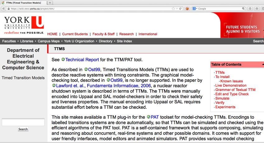
FTSCS’13

           Contents

              •   Introduction
              •   TTM/PAT: Architecture
              •   TTM/PAT: Resources
              •   Contributions
              •   A Pacemaker Example
              •   A TTM for Pacemaker
              •   Evaluation: A Nuclear Shutdown System
              •   More in this Paper: TTM Semantics
              •   Extended Work: Compositional Reasoning
              •   Conclusion
              •   Further References

                                                           index
FTSCS’13

           Introduction

            • Timed Transition Models (TTMs)
               – guarded transition systems for describing reactive systems
               – found useful in modelling a production nuclear reactor SDS
                 ∗ TTMs were represented manually in “foreign” languages

            • We propose a textual modelling language for TTMs:
               – a discrete time domain                               [t ick event]
               – system as a composition of module instances
               – global & local timers                             [monotonicity]
               – demonic assignments                   [compositional reasoning]
               – time bounds & fairness constraints                  [event level]
               – LTL properties language                       [untimed & timed]
            • “native” tool support in PAT                [simulation & checking]

                                                                                      index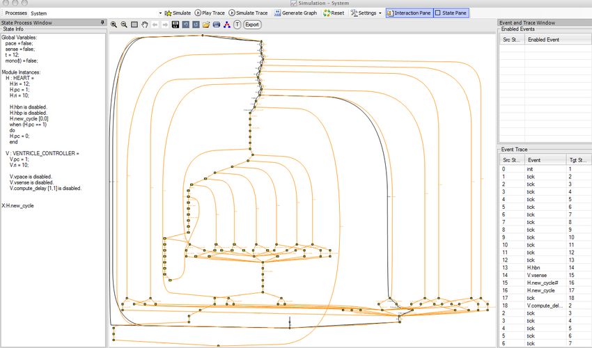
FTSCS’13

           TTM/PAT: Architecture

                                                          TTM
                                                         Module

           Reference: http://www.comp.nus.edu.sg/~pat/

                                                                  index
FTSCS’13
TTM/PAT: Resources
Reference: https://wiki.eecs.yorku.ca/project/ttm/
indexFTSCS’13
Contributions
1. The textual syntax for the TTM notation
2. An operational semantics for TTMs using LTS (i.e., digitization)
• for this talk, we do not address it in details [see the paper]
3. Implemented tool support in PAT
indexFTSCS’13
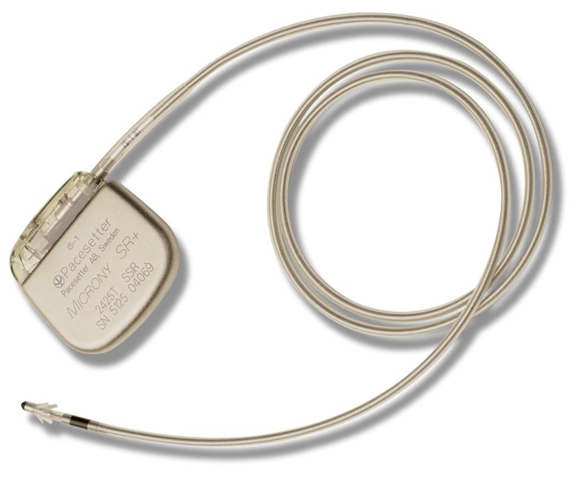
A Pacemaker Example
an electronic device implanted into the body to
• detect (or sense) natural cardiac stimulations
• regulate the heart beat by delivering electrical stimuli (or paces)
– over leads with electrodes that are in contact with the heart
indexFTSCS’13
In the VVI mode, the hysteresis rate interval (HRI=1200ms) is the default
maximum time between two consecutive sensing’s.
Case of Pacing: no sensing has occurred within the current rate
interval, then
• a pace is delivered
• hysteresis pacing is disabled by restricting the new cycle to the
lower rate interval (LRI = 1000ms)
Case of Sensing: a heartbeat is sensed within the current rate interval,
then
• further sensing is disabled for a ventricular refractory period (VRP =
400ms) to avoid noise following the heartbeat
• once VRP is over, the cycle is relaxed to a larger HRI without
delivering a pace
indexFTSCS’13
Heart Ventricle Controller
new_cycle[0, 0] computer_delay[1, 1]
start t hbn[VRP, *] vsense[0, 0]
when !pace when sense
do ri := HRI, do ri := HRI,
sense := true , sense := false
hbp[0, 0] vpace[0, 0]
when pace ^ t VRP when !sense && t = ri
do ri := LRI, do ri := LRI,
pace := false pace := true
new_cycle[0, 0] computer_delay[1, 1]
start t
indexFTSCS’13
A TTM for Pacemaker
Constants and timers
#define VRP 400;
#define LRI 1000;
#define HRI 1200;
timers
t: 0 .. (HRI+1) enabledinit
end
share initialization
sense: BOOL = false // channel: sent from Heart, received by Controller
pace : BOOL = false // channel: sent from Controller, received by Heart
end
indexFTSCS’13
Module of Environment – the human heart
module HEART hbp[0,0] // paced heart beat
interface
when pace && VRPFTSCS’13
Module of Controller – the ventricle controller
module VENTRICLE_CONTROLLER vsense[0,0]
interface when pc==0 && sense
pace : share BOOL do ri := HRI,
sense: share BOOL sense := false,
local pc :=1
ri : INT = HRI end
pc: INT = 0
events compute_delay[1,1]
vpace[0,0] when pc==1
when pc==0 && !sense && t==ri do pc:= 0
do ri := LRI, end
pace := true, end
pc:= 1
end
indexFTSCS’13
Module Instantiations & Compositions
instances
H = HEART (share pace, share sense)
VC = VENTRICLE_CONTROLLER (share pace, share sense)
end
composition
System = H || VC
end
We also support iterated composition, e.g., in the Fischer’s algorithm:
composition
fischer = || i: 1..n @ PROCESS(share x, share c, in i)
end
indexFTSCS’13
Properties Language: TTM vs Uppaal
Assertion TCTL of Uppaal LTL of TTM/PAT
Henceforth p S |= A p S |= p
Eventually p S |= A◊ p S |= ◊ p
Whenever p, eventually q S |= p −→ q S |= (p → (◊ q))
Infinitely often p S |= t rue −→ p S |= ◊ p
Referring to a state M .st at e pc = st at e
Non-Zenoness × S |= ◊ t ick
p until q × S |= p U q
q releases p × S |= q R p
Nesting of temporal operators × e.g., (◊ p → (pU q))
Referring to occurrences of event e × e
Timer t has increased monotonically × mono (t)
Eventually henceforth p × S |= ◊ p
S possibly maintains p S |= E p inverse of S |= ◊ (¬p)
S possibly reaches p S |= E◊ p S reaches p
Nesting of path quantifiers × ×
∀◊ ∀ p × ×
indexFTSCS’13
Formalizing Requirements
We translate a list of requirements into LTL formulas:
1. A natural heartbeat occurs only in the interval [VRP, H.last_ri] in
the cardiac cycle.
System |= (H.hbn ⇒ VRP ≤ t ≤ H.last_ri)
We couldn’t use H.ri since it has already been changed by H.hbn.
2. Infinitely often, a natural or paced heart beat occurs between VRP
and HRI time units from each other (note. LRI < HRI).
No events illegally set the value of timer t.
System |= ( H.new_cycle ∧ t = 0 ⇒
mono(t)U ( (H.hbn ∨ H.hbp) ∧ VRP ≤ t ≤ HRI ) )
indexFTSCS’13
We also translate a list of healthiness conditions into LTL formulas:
1. Clock ticks infinitely often (non-Zeno behaviour).
System |= ◊tick
2. Timer t is always bounded by HRI.
System |= (t 6= HRI + 1)
indexFTSCS’13
Demo:
Locating the Pacemaker Example
indexFTSCS’13
TTM/PAT: Static Type Checking
indexFTSCS’13
TTM/PAT: Generating Reachability Graph
indexFTSCS’13
TTM/PAT: Graphical Simulation
indexFTSCS’13
TTM/PAT: Verification
indexFTSCS’13
TTM/PAT: Generating Counter-Example
indexFTSCS’13
TTM/PAT: Traceability of Counter-Examples
indexFTSCS’13
Evaluation: A Nuclear Shutdown System
Context Diagram of SDS State Diagram of SDS Controller
both_hi[1,1] delay[29,29]
Nuclear Reactor
power_low[1,1]
power_hi[1,1]
relay:=open
power_hi[1,1]
SDS Controller delay[19,19]
Pressure power_low[1,1]
Trip Relay relay:=close
Power
Analog Implementation of SDS Controller
Pressure
AND Timer1
AND Timer2 Relay
Power
indexFTSCS’13
Liveness & Safety Properties
Liveness – Response Formula F r es :
Henceforth, if Power and Pressure simultaneously exceed their threshold
values for at least 2 clock ticks, and 30 ticks later Power exceeds its
threshold for another 2 ticks, then within 30 to 32 ticks, open the reactor
relay for at least 20 ticks. [pattern: (p ⇒ ◊q)]
Safety – Recovery Formula F r ec :
Henceforth, if the relay is open for 20 ticks, and after the 20th tick the
power is low for at least 2 ticks, then the relay is closed before the 22nd
tick. [pattern: ( ¬(Tpower_low = 2 ∧ r ela y = open) )]
indexFTSCS’13
TTM/PAT outperforms manual encodings in Uppaal and SAL
TTM:
Property Controller Model ◊ t ick Result TTM/PAT Uppaal SAL
SP EC 11 × 11 13 25
F r es :
PROG 31 × 32 24 407
System
Response S P EC r 5 × 3 12 15
PROG r 14 × 9 21 330
SP EC .5 Ø .4 .9 11
PROG 1 Ø 1 1 20
Fir es : S P EC r .3 Ø .2 .4 7
Initialized
System PROG r .8 Ø .6 1 13
Response S P EC r1 ||S P EC r2 16 Ø 11 62 235
PROG r1 ||PROG r2 109 Ø 70 76 >1h
#states: 421,442 #states: 1,771,396
#trans.: 821,121 #trans: 1,771,396
SP EC .3 × .08 .1 6
PROG .8 × .2 .3 7
F r ec :
S P EC r .1 Ø .07 .2 4
System
Recovery PROG r .3 Ø .07 .6 5
S P EC r1 ||S P EC r2 22 × .06 145 18
PROG r1 ||PROG r2 142 × .1 11 >1h
Unit of Measurement: Seconds
indexFTSCS’13
More in this Paper: TTM Semantics
• Abstract Syntax
• Single Machine
– Digitation using LTS
– turning event occurrences (e.g., t ick) into state predicates
– scheduling
∗ real-time: time bounds [l, u]
· e.g., spontaneous ([0, ∗]), instantaneous ([0, 0])
∗ fairness assumptions: just (weak) vs compassionate (strong)
∗ e.g. just ent er[0, ∗] when ... do ... end
• Multiple Machines
– module instantiation
– module composition
– iterated composition
indexFTSCS’13
Extended Work: Compositional Reasoning
• Motivation. local reasoning w.r.g. an arbitrary environment
• Rule
m1 |=m P m2 `m Q
P ∧Q ⇒ R
m1 || m2 |= R
• Demonic, non-deterministic assignments to model event actions:
type
STATE = {low, high}
a :: 2 .. 100
end events
b :: BOOL
module Plant update[1, ∗]
c :: {on, off}
interface do power :: STATE,
d :: ARRAY[STATE](20)
power : out STATE = low pressure :: STATE
pressure : out STATE = low end
indexFTSCS’13
Conclusion
• textual syntax for the convenient, expressive TTM notation
– modules, events, time bounds, fairness assumptions
– untimed and timed LTL properties [mono. of timer, non-Zeno]
• LTS semantics (i.e., digitization)
• tool support for automated encoding: TTM/PAT
– static type checking
– graphical simulation
– model checking & traceable counter-examples
• significantly better performance than encodings in Uppaal and SAL
• will improve the performance (e.g., BDD, DBM)
• event-based syntax is amenable to theorem proving when model
checking runs out of steam!
indexFTSCS’13
Further References
• Compositional Reasoning using TTM/PAT
J. S. Ostroff, C.-W. Wang, and S. Hudon. (2013) TTM/PAT: A Tool
for Modelling and Verifying Timed Transition Models. Tech Report
CSE-2013-05.
indexFTSCS’13
Please Question/Comment/Criticize.
indexFTSCS’13
Index
2 Contents
3 Introduction
4 TTM/PAT: Architecture
5 TTM/PAT: Resources
6 Contributions
7 A Pacemaker Example
10 A TTM for Pacemaker
10 Constants and timers
11 Module of Environment – the human heart
12 Module of Controller – the ventricle controller
13 Module Instantiations & Compositions
inFTSCS’13
14 Properties Language: TTM vs Uppaal
15 Formalizing Requirements
18 TTM/PAT: Static Type Checking
19 TTM/PAT: Generating Reachability Graph
20 TTM/PAT: Graphical Simulation
21 TTM/PAT: Verification
22 TTM/PAT: Generating Counter-Example
23 TTM/PAT: Traceability of Counter-Examples
24 Evaluation: A Nuclear Shutdown System
25 Liveness & Safety Properties
26 TTM/PAT outperforms manual encodings in Uppaal and SAL
27 More in this Paper: TTM Semantics
28 Extended Work: Compositional Reasoning
inFTSCS’13
29 Conclusion
30 Further References
32 Index
indexYou can also read