Installation Guide Version 2.0i August 2021 - Scientific Aviation
←
→
Page content transcription
If your browser does not render page correctly, please read the page content below
Installation Guide Version 2.0i August 2021
Quick Start:
1. Install the SOOFIE hardware (pages 6 – 11).
2. Open the iOS app and enter site info (pages 12 – 13).
3. In the app, click     and then     to begin
   monitoring.

                                                     2
SOOFIE parts list
                               Label Qty.   Description
       A     C   D
                               A      x1    SOOFIE enclosure
                               B      x1    solar panel
                               C      x1    solar panel upper bracket
                        E      D      x2    solar panel lower brackets
                               E      x1    U-bolt with mount plate and nuts
                               F      x3    Unistrut clamps
                        F
                               G      x1    14” Unistrut channel
                               H      x2    7.8” Unistrut channels
                               I      x6    square Unistrut washers

                        G, H   Bag:   x4    10-32 x 2” pan head Phillips machine screws
                                      x4    ¼”-20 x ⅝” hex head bolts
                                      x2    ¼”-20 x 1-¾” hex head bolts
                                      x4    #10 screw size flat washers
                        I             x4    #10 screw size split ring lock washers
B                                     x6    ¼” screw size split ring lock washers
                                      x2    ⅜” screw size split ring lock washers
                        Bag           x6    ¼”-20 hex nuts
                                      x2    splashproof fuse receptacle caps
                                      x2    10 Amp medium-blow cartridge fuses

                                                                                          3
Anemometer Parts List

                        Label Qty. Description
                        S    x1    sonic anemometer
                        T    x1    cable
                        U    x1    mounting stub
                        V    x2    hose clamps
                        W    x3    10-32 x 3/8” pan head Phillips machine screws

                                                                           4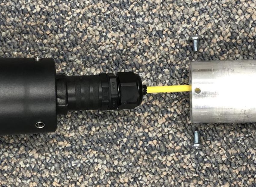
Installation tools (supplied by the user)

                    Needed for installation:
                    Phillips screwdriver, 2-point tip
                    Slotted screwdriver, 1/4” tip
                    3/8” drive ratchet handle
                    5/16” socket
                    7/16” socket

      Tools         1/2” socket
                    9/16” deep socket
                    7/16” open-ended wrench
                    1/2” open-ended wrench
                    6” diagonal cutting pliers
                    8” slip-joint pliers
                    Small tape measure
                    Marker pen
                    Stepladder
                    Recommended:
                    Electric screwdriver set with variety of tips – Phillips, slotted, and hex sockets as
                    listed above, & Multimeter for troubleshooting.

                                                                                                            5
Installation procedure
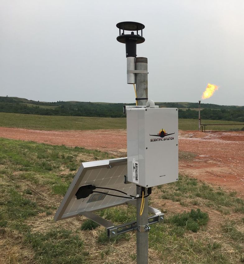
1a. (if applicable) Attach the anemometer to the stub.
1) Attach the cable to the anemometer. 2) Pass the cable through the mounting stub
Rotate the plug to align with the keyed and attach the stub to the anemometer
receptacle; twist the sleeve several turns using three 10-32 x 3/8” pan head Phillips
clockwise to lock the plug (feel for a ‘click’ machine screws. Tighten to 20 in-lbs.
to ensure the lock mechanism is engaged).
6
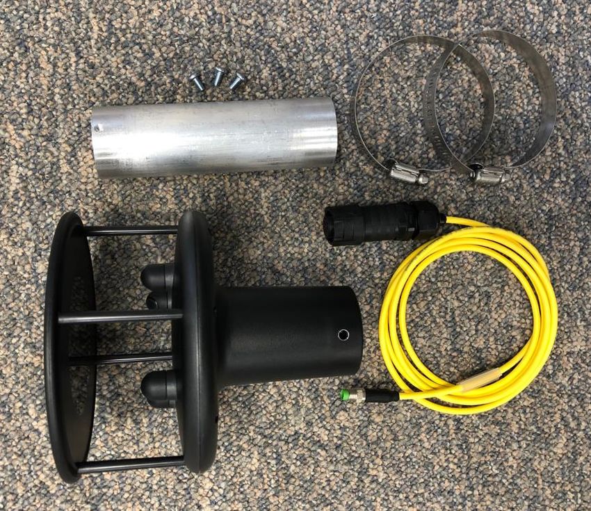
1b. (if applicable) Attach the anemometer to the pole.
4)   Position the anemometer & stub assembly     5)   Orient the assembly so the measurement
     at the top of the pole on the South side.        plane is horizontal and the North arrows
     Install two hose clamps around the stub          and colored security seal (circled below)
     and the pole and spaced 3” apart.                point to true North after the hose clamps
                                                      are securely tightened.

                                                                                                  7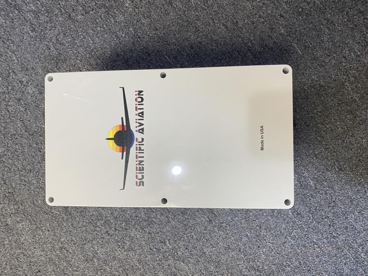
2a. Attach the solar panel to its mounting frame.

                      1)   Measure & mark the pole at 6.0”, 13.5”, and 29.5” from the top.
                      2)   Position the solar panel upper mounting bracket with the bend
                           facing the solar panel and attach with two ¼-20 x 5/8” hex head
                           bolts, lock washers, and nuts. Tighten nuts to 75 in-lbs.
                      3)   Attach two solar panel lower mounting brackets to the other
                           edge of the solar panel with two ¼-20 x 5/8” hex head bolts,
                           lock washers, and nuts. Tighten nuts to 75 in-lbs.
                      4)   Attach the other ends of the lower mounting brackets to the
                           14” long Unistrut channel with two ¼ -20 x 1.75” hex head
                           bolts, square Unistrut washers, lock washers, and nuts. Tighten
                           nuts to 75 in-lbs. Support the Unistrut channel and lower
                           mounting brackets to avoid bending the solar panel frame.
                      5)   Place the solar panel and frame assembly at the base of the
                           pole and facing South.

                            (Continued on next page)

                                                                                    8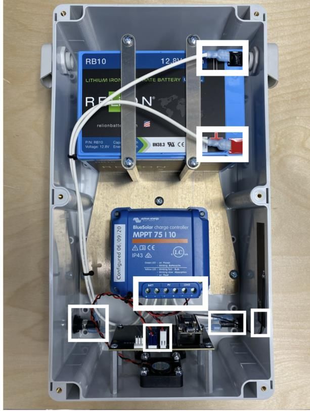
2b. Attach the solar panel to the pole.

                        6)   Position the U-bolt around the pole, through the solar panel
                             upper mounting bracket, and through the rectangular U-bolt
                             mounting bracket. Install two 3/8” lock washers and nuts,
                             and leave loose.
                        7)   Attach a Unistrut clamp to the Unistrut channel at the base
                             of the pole, install the pole clamp bolt and nut, and leave
                             loose.
                        8)   Slide the solar panel assembly up the pole to position the U-
                             bolt at the 13.5” mark and the top of the Unistrut clamp at
                             the 29.5” mark below the top of the pole. Support the
                             Unistrut channel to avoid bending the solar panel frame.
                        9)   Ensure the panel is facing South; tighten the Unistrut clamp
                             (75 in-lbs) and the U-bolt nuts (120 in-lbs) to secure the solar
                             panel to the pole.

                                                                                        9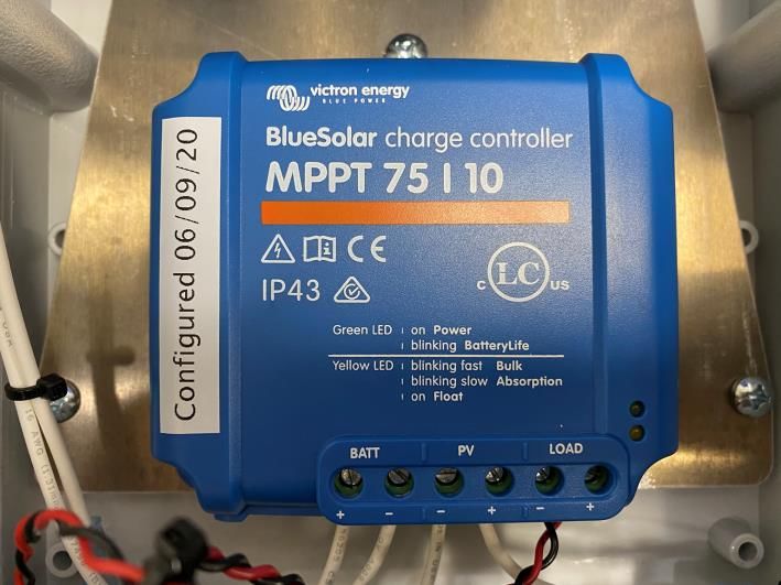
3. Attach the SOOFIE enclosure to the pole.

                   1)   Attach two 7.8”-long Unistrut channels to back of the SOOFIE
                        enclosure with four 10-32 x 2” pan head Phillips screws, #10
                        lock washers, #10 flat washers, and square Unistrut washers.
                        Torque to 16 in-lbs (1.8 Nm).
                   2)   Position the top of a Unistrut clamp at the 6.0” mark below
                        the top of the pole and engage the upper Unistrut channel
                        on the SOOFIE enclosure. Slide the enclosure to the side
                        closest to the solar panel junction box.
                   3)   Position another Unistrut clamp around the pole and engage
                        the lower Unistrut channel on the SOOFIE enclosure.
                   4)   Tighten both Unistrut clamps securely (75 in-lbs).

                                                                                      10
4. Power up the system and connect the cables.
1) Insert a 10A medium-blow fuse into a fuse receptacle cap;
push in FIRMLY and turn clockwise to install in the left-hand
fuse receptacle. Confirm fuse cap is locked and confirm
audible fan operation. This fuse completes the battery circuit;
SOOFIE is now operating!
2) Insert the (+) and (–) connectors from the solar panel into
the MC4 receptacles on the SOOFIE enclosure. Confirm both
connectors are fully inserted and locked.
3) Insert a 10A medium-blow fuse into a fuse receptacle cap;
push in FIRMLY and turn clockwise to install in the right-hand
fuse receptacle. Confirm fuse cap is engaged and locked.
This fuse completes the solar panel charging circuit.
4) (if applicable) Insert the anemometer cable connector into
the M8 receptacle on the SOOFIE enclosure and rotate the
knurled barrel on the cable connector until finger-tight.
115a. Enter and upload site data
using the SOOFIE iOS app
1. Go to the App Store and download the SOOFIE
app to your iOS device.
2. Confirm that the iOS default Mail app
is installed and configured on your iOS device.
3. Open the SOOFIE app and type in a name for this
site.
4. Click the button. Please wait a few
seconds while precise GPS coordinates are
captured, and the camera view activates.
5. Using the camera, scan the bar code located on
the side of an installed SOOFIE sensor box. The
box name and location data will appear in the
field below “Devices”. If you’ve made a mistake,
just swipe left to delete an entry, and re-scan.
6. Repeat this scan process for each SOOFIE box at
the site.
125b. Enter and upload site data
using the SOOFIE iOS app
6. Next, you’ll need to geotag each component
SOOFIE app email example
on the site so that SOOFIE can automatically
identify source locations.
7. Walk up to each facility component (tank,
wellhead, compressor, flare, etc.), type in a
unique name in the COMPONENT field, and
click the button to add it to the
database. Repeat this process for each
component at the site. If you’ve made a
mistake, just swipe left to delete an entry,
and re-enter.
8. When all site components and SOOFIE
sensor boxes have been added, click
the button. A draft email to
SOOFIE@scientificaviation.com will appear.
9. After reviewing, click the button to
upload the site data and begin monitoring.
10. Please confirm with SOOFIE team that your
devices are up and running before leaving
the site.
13Troubleshooting
1. Open the SOOFIE enclosure.
1) Loosen all 6 recessed cover screws and remove cover.
NOTE:
Cover screws are not captive; do not flip the cover over.
CAUTION:
High-current DC voltage up to 25v is exposed with cover off.
142. Check fusing and wiring.
NOTE:
The two fuses are interchangeable, but their removal/reinsertion
order is important. The solar panel fuse MUST be removed first
AND reinserted last, following the sequence below.
1) Remove the solar panel fuse from right-hand fuse holder by
pushing in firmly and turning counter-clockwise ½ turn;
ensure fuse is intact or replace with a new 10A 250V
medium-blow 1/4" x 1-1/4” glass cartridge fuse.
2) Remove the battery fuse from left-hand fuse holder by
pushing in firmly and turning counter-clockwise ½ turn;
ensure fuse is intact or replace with a new 10A 250V
medium-blow 1/4" x 1-1/4” glass cartridge fuse.
3) Reinsert the battery fuse into left-hand fuse holder.
4) Reinsert the solar panel fuse into right-hand fuse holder.
5) Confirm that all cables are firmly captured in MPPT solar
controller screw terminals.
6) Confirm that crimp terminals are fully engaged on battery
and fuse holder tabs.
7) Confirm that the MTA connectors on the sensor board are
properly seated.
153. Check and record voltages.
With a voltmeter, check and record DC voltages between:
1) Terminals on LiFePO4 battery: vDC
2) BATT terminals on MPPT charge controller: vDC
3) PV terminals on MPPT charge controller: vDC
Note: PV terminal voltage will be zero unless the
solar panel is connected and exposed to the sun
4) LOAD terminals on MPPT charge controller: vDC
164. Check operation
1) Check that the intake fan is running.
2) Check the two LEDs on the MPPT solar charge controller:
a. Green LED on or blinking? (power from battery)
b. Yellow LED on or blinking? (charging from panel)
3) Check the status LED on the Particle Boron/Argon
microprocessor:
a. pulsing cyan? (connected to Internet)
b. blinking green? (looking for cellular/wifi service)
c. magenta? (firmware update in progress)
If these steps have identified an obvious problem with no immediate solution, please call
Scientific Aviation at (303) 551-2005.
17You can also read