Installation & User Instructions - PROFESSIONAL INSTALL ONLY Praetorian Guard IP Intercom
←
→
Page content transcription
If your browser does not render page correctly, please read the page content below
Installation & User Instructions
            Praetorian Guard IP Intercom

     PROFESSIONAL INSTALL ONLY

                    Manual Version 1.1

            Tip: Site Survey BEFORE you begin.
                        See page 4-5

1|P a g e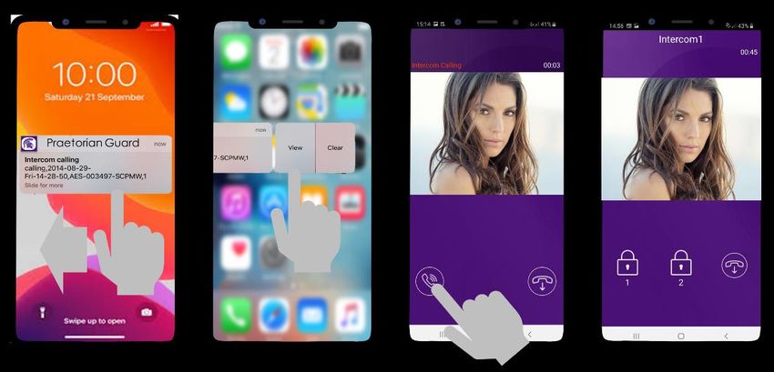
Index
                                                                    Section     Pages

                                                 PHASE 1 – SITE SURVEY          4-5
                                                        Site Survey (LAN)       4
                                                       Site Survey (WiFi)       5

                                        PHASE 2 – PRODUCT OVERVIEW              6-14
                                                   Overview of Call Points      7-10
                                        Overview of Optional Extra Devices      11
                                                            More Detail….       12-14
                                                    PCB Module Overview         15
                                                  Technical Specifications      16-18

                                                       PHASE 3 - SETUP          19-30
                                                    Configure Before Install    19
                                            Connect to network using WiFi       20-24
                                       Connect to network using LAN Cable       25-26
                                                      Time Sync & Testing       27-28
                                                     Answering on Android       29
                                                 Answering on iOS (Apple)       30

                                                PHASE 4 - INSTALLATION          31-40
                                   How to Achieve & Maintain IP55 Rating        32
                                          Installation (Wi-Fi) & (LAN Cable)    33
                                                        Power & Solar Power     34
                                         LAN Cable & WiFi Setup Example         35
                                                        PCB Wiring Example      36
                            Exit Button (PTE) & Connecting Slave Devices        37
                                              Adding Additional APP Users       38
            Sound, Volumes and Speech / Intercom & Device Sound Options         39
                                                        Using Keypad Codes      40

                                            PHASE 5 – ADVANCED SETUP            41-52
                                      Feature Shortcuts & Settings Overview     42
                                                          Standard Features     43
                                Edit Intercom Details / Add a New Device ID     44
                              Ringtones of In-app Call / Check APP version      45
              Check Intercom Firmware / Add, Edit or Delete Users & Logins      46
                          Adjust Relay Trigger Times / Adjust Intercom Time     47
                           Wi-Fi Settings / Adjust Maximum Monitoring Time      48
              Adjust Maximum Talking Time / Adjust Maximum Calling Time         49
                        Reboot Intercom / Simplex / Duplex Audio Selection      50
                                  Advanced Feature Overview / Notifications     51
                             Auto Relay Times / Camera Stream Resolution        52
                                                                 Activity Log   53
                                                              Keypad Codes      54
                                                        PROX Cards/Tag IDs      55
              Voicemail Option for missed Callers / Motion Detection Option     56

                                                           Troubleshooting      57-58

                     App Updates / Firmware Updates / Extra Resources           59

        Intercom Maintenance / Environmental Information / Ingress              60

                                                                   Warranty     61

2|P a g e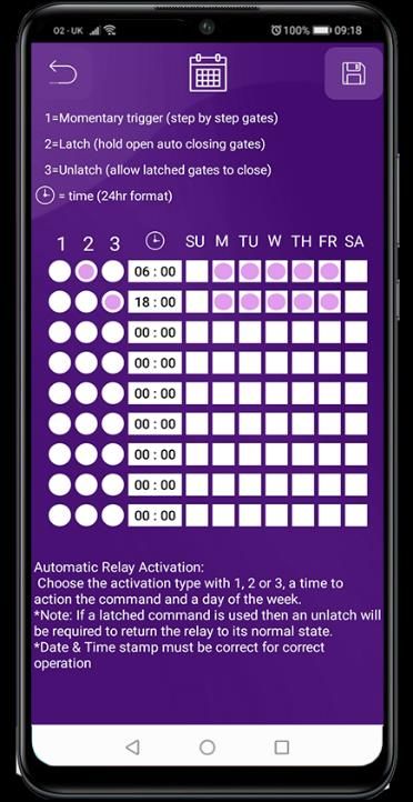
PHASE 1
            Site Survey

3|P a g e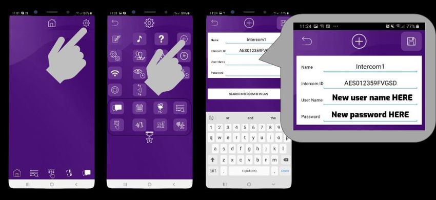
Site Survey (LAN)

            Mbs
                                              Upload Speed
                                              I have at least 1.5 Mb UPLOAD speed. If not
                                              STOP! This system may operate intermittently
     Slow            Fast                     remotely or have delayed PUSH notifications.

                                              Cable Distance
                                              My cable run does not exceed 100m in total
                                              distance. If it does then a powered switch is
                                              required to be fitted in-line to extend the signal.

  The Praetorian Guard is designed to transmit the video and audio stream using on average
  400 KBit/sec (peaking to 1Mbps). This loosely translates to requiring a minimum of 1.5Mbps
  UPLOAD speed on the network that the intercom is connected to. The higher the upload
  speed the better quality of image up to an approx. max of 4Mbps upload speed.

  If you do not have sufficient upload speed then please look at upgrading your internet package,
  if possible.

   Please consult someone with network knowledge if you need help with these steps.

4|P a g e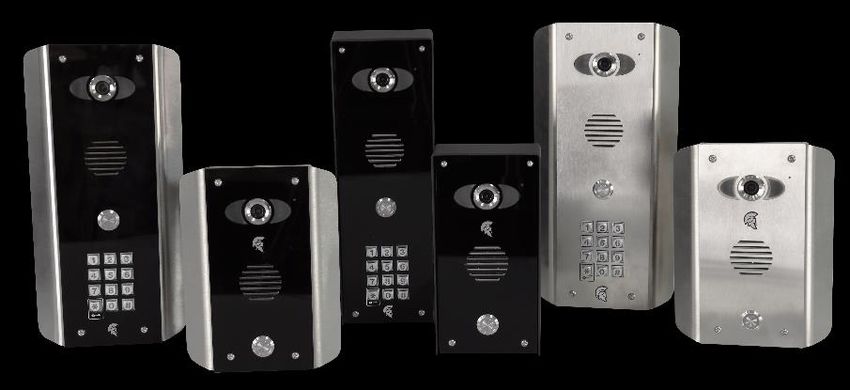
Site Survey (Local WiFi)

       WiFi                               WIFI Signal
                                          I have some WiFi signal at the gate with my
                                          phone! If not, STOP. You will need some form
                                          of WiFi extender, or repeater, or LAN/CAT5
                                          cable!

               Mbs
                                           Upload Speed
                                           I have at least 1.5 Mb UPLOAD speed. If not
                                           STOP! This system may operate intermittently
                                           remotely or have delayed PUSH notifications.
        Slow          Fast

                                           YES!
                                           My WiFi Internet Security is WPA, WPA2,
                                           WPA3 or better.

   Total distance of WiFi range will depend heavily on the property network setup.
   Max distance is 60m based on using a basic home router passing through 1
   exterior wall. For the most reliable connection utilize the LAN or 4G Router options.

   WiFi Signal Explained

   Poor = System may not show ONLINE. Signal may drop out regularly or cause
   delay’s on the video loading or stop notifications receiving from being sent.

   Fair = System will operate as expected in most instances. Signal may drop out from
   time to time or cause delay’s on the video loading or stop notifications receiving
   from being sent.

   Good / Excellent = System will operate as expected in all instances. Signal should
   never drop or cause delay’s on the video loading

   Please consult someone with network knowledge if you need help with these steps.

5|P a g e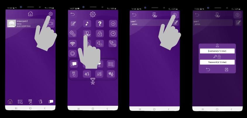
PHASE 2
        Product Overview

6|P a g e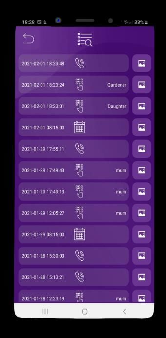
Overview of Call Points (Modular Design)

            PRAE-IP-MOD                 PRAE-IP-MOD-KP

        PRAE-IP-MOD-PX                 PRAE-IP-MOD-PX-KP

            Overview of Call Points (Modular Design)

  PRAE-4GXX-MOD-ROUTER             PRAE-4GXX-MOD-KP-ROUTER

PRAE-4GXX-MOD-PX-ROUTER           PRAE-4GXX-MOD-PX-KP-ROUTER
7|P a g e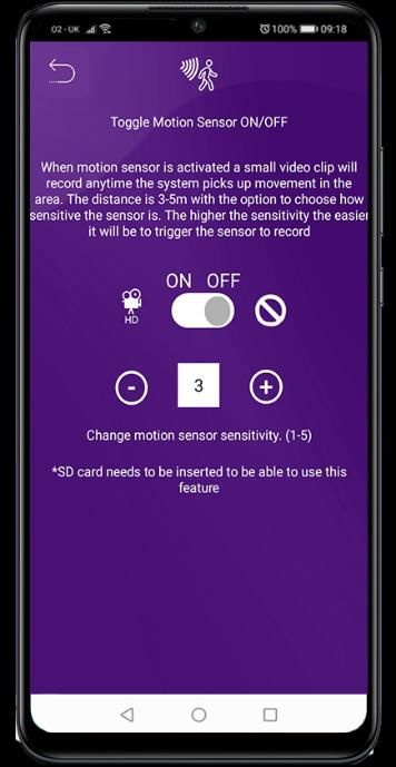
Overview of Call Points (Architecture Design)

            PRAE-IP-AB                   PRAE-IP-AS

            PRAE-IP-ABK                 PRAE-IP-ASK

        PRAE-IP-PX-ABK                 PRAE-IP-PX-ASK

8|P a g e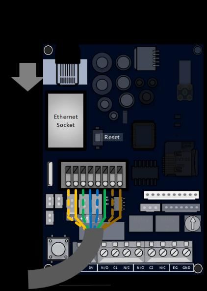
Overview of Call Points (Portrait Flush Design)

             PRAE-IP-FB                  PRAE-IP-FS

            PRAE-4GXX/FBK                PRAE-IP-FSK

       PRAE-IP-F-PX-ABK               PRAE-IP-F-PX-ASK

9|P a g e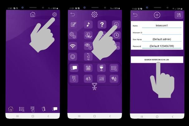
Overview of Call Points (Pedestal Design)

               PRAE-IP-PED                  PRAE-IP-KP-PED

          PRAE-IP-PX-PED                   PRAE-IP-PX-KP-PED

               Overview of Call Points (Pedestal Flush Design)

               PRAE-IP-PED-F               PRAE-IP-PED-F-KP

10 | P a g e
Overview of Optional Extra Devices
MON-11 POWER CONDITIONING MODULE
TBC (future addition late 2021) TBC (future addition late 2021)
11 | P a g eMore Detail….
Architectural Model
Security
screw access
Colour camera with
night vision and IR
cut filter
Waterproof
Mylar 1.5W
speaker
Optional PROX
reader
Optional
illuminated
keypad.
Illuminated IP67
push button
Microphone
Mounting holes
Cable entry hole
Optional Keypad
& PROX module 12-24v
OUT
1 2 3
SLAVE OUT
+12v-
OUT
12-24v 1 2 3
IN SLAVE IN
1 23
OUT
1 23
IN
12-24v SLAVE OUT
1 2 3
12-24v
OUT
IN
SLAVE IN
12-24v 1 2 3
IN
Main intercom
module
Call button
Camera module
12 | P a g eModular Version
Security Colour camera with night
screw access vision and IR cut filter
Waterproof
Mylar 1.5W Infra-red night
speaker vision illuminators
Illuminated IP67
push button
Optional
illuminated
keypad.
Microphone
Mounting holes
Cable entry hole
Optional Keypad
& PROX module 12-24v
OUT
1 2 3
SLAVE OUT
+12v-
OUT
12-24v 1 2 3
IN SLAVE IN
1 23
OUT
1 23
IN
12-24v SLAVE OUT
1 2 3
12-24v
OUT
IN
SLAVE IN
12-24v 1 2 3
IN
Call button
Camera module
Praetorian IP
Module
13 | P a g ePedestal Version
Optional
PROX Cam Security
Reader Lock
Microphone Camera
Night vision
LEDs Speaker
Module
Optional
Keypad
Call Button
Pedestal
mounting holes
Call button
IP PCB
12-24v
OUT
1 2 3
SLAVE OUT
+12v-
OUT
12-24v 1 2 3
IN SLAVE IN
1 23
OUT
1 23
IN
12-24v SLAVE OUT
1 2 3
12-24v
OUT
IN
SLAVE IN
12-24v 1 2 3
IN
Optional keypad Camera
module module
14 | P a g eMain IP Module in Detail…
Intercom ID
Antenna SMA Connector
RJ45 Socket
LED Indicators
Hard Reset RED = Network Connection
Button BLUE = Power
Direct LAN cable Micro SD
Connection Card Slot
Voltage Outputs
Keypad Data Cable
Push Button, Mic & Connections
Speaker Connections
Volume ‘POT’
Direct Hotspot Button
24V DC Relay 1 Relay 1 Push to
Input N/O–COM–N/C N/O–COM–N/C exit input
(EG/COM)
Keypad & PROX Module’s in Detail
*optional extra
Slave OUT Slave IN
DC Voltage
12-24v
1 2 3 Connections Connections
OUT
SLAVE OUT
Out
+12v-
OUT
12-24v 1 2 3
IN SLAVE IN DATA Transfer
OUT
1 23
OUT
1 23
IN
Baud Rate DATA Transfer
Jumper Link 12-24v SLAVE OUT IN
SLAVE IN
12-24v
OUT 1 2 3
12-24v 1 2 3
IN
IN
DC
Voltage In Slave OUT DC Voltage
Connections In
Slave IN DATA
Connections Transfer IN
15 | P a g eTechnical Specifications
GENERAL
Front Panel Portrait Orientation
AB/ABK = 3mm Acrylic on Architectural Design Marine Grade
Stainless Steel BS316 Front Plate
AS/ASK = 3mm Marine Grade Stainless Steel BS316 on Architectural
Design Marine Grade Stainless Steel BS316 Front Plate
FS/FSK = Flush Design Marine Grade Stainless Steel BS316 Front
Plate
IMP/IMPK = 3mm Acrylic on Imperial Design Marine Grade Stainless
Steel BS316 Front Plate
Modular = Powder Coated Marine Grade Stainless Steel BS316 Front
Plates with 3mm Acrylic on Design Marine Grade Stainless Steel
BS316 Modular Plates
Landscape Orientation
PED = Pedestal Surface Mount
Hood Cover Powder coated Aluminium
(MOD, IMP(K), PED)
Mounting Housing (Backbox) Marine Grade Stainless Steel BS316
Call Button Stainless-steel button with illuminated LED Ring
Weatherproof IP55
Approvals CE, FCC
Dimensions See Datasheets
Operating Temp. -25 to +55°C / -13 to 131°F
Power Supply 24V DC
Power Consumption IP PCB w/Keypad & Prox
Standby = 96mA
Operating = 500mA
Peak = 2000mA
Solar Power 30Watt Solar Panel (minimum)
24V 10AH
16 | P a g eSystem Requirements Mobile device: Newest iOS on iPhone/iPad,
newest Android on Smartphone/Tablet
Internet: High-Speed Landline Broadband
Internet connection, DSL, cable or fibre optic,
no socks or proxy server. Min. suggested upload speed of 1.5Mbps,
Network: Ethernet Network, with DHCP / WIFI 2.4GHz/5.8GHz (with
applicable antenna)
Recommended Installation Camera lens should be at a min. height of
Height 145 cm (57 in). Before the installation please
determine your optimal installation height.
KEYPAD MODULE
Power Supply 24V DC
Steel Keypad Module 12 Square Metal Keys
Blue illumination
Keypad Codes configurable via App,
Slave connection to allow up to an additional 8 slave devices
Silicon Keypad Module 12 Round Silicon Keys
Blue illumination
Keypad Codes configurable via App,
Slave connection to allow up to an additional 8 slave devices
VIDEO
Camera HD 720p, dynamic (VGA – HD)
Lens 120° (D), 109° (H), 65° (V)
IR-capable
Display Resolution Switchable in the app by the Admin user.
HD resolution: 1280*720
SD resolution: 640*480
Video Codec H264
Night-Vision Yes, light sensor, automatic IR-cut filter,
5 Infrared LEDs
17 | P a g eStorage On-Board Micro SD Card (16GB included)
Max read capacity 32GB
Estimated capacity based on 16GB:
5,592 Video Clips (3MB) {AVI.}
33,500 images (0.5MB) {JPG}
Supports Hot Swapping.
Auto overwrites oldest data at 70% capacity
FAT32 Formatting
MOTION SENSOR
Type Active
Detection Type Digital (Pixel-based)
Changes of pixilation. This is processed by the CPU identifying any
major/minor changes in pixels that is defined by a predetermined
algorithm.
Range >5m, depends on environment, distance is fixed
Configuration Via App, e.g.
• Sensitivity (1-5)
• Enable/disable push notification
• Enable/disable detection & recordings.
AUDIO
Audio Components Speaker and microphone, noise reduction and
echo cancellation (ANR, AEC)
Audio Streaming Two-way, full duplex & half-duplex
(switchable in-app)
Audio Codec PCM/ARAW
NETWORK
WiFi IEEE 802.11a/b/g/n/ac
WiFi Security WPA / WPA2 / WPA3
Frequency Range 2.4GHz-2.4385GHz; 5.15GHz-5.845GHz
Ethernet IEEE 802.3
Supported Protocols HTTP, HTTPS, SSL/TLS, Bonjour, DNS, RTSP, RTP, TCP, UDP, RTCP,
ICMP, DHCP, ARP
THIRD-PARTY INTEGRATIONS
Partners N/A - Coming Soon
API N/A - Coming Soon
18 | P a g ePHASE 3
Setup
(To be done before installing the intercom)
19 | P a g eConfigure Before Install
Step 1
Do not install the intercom. Power it up beside
3 - 4 feet / 1 meter the router so that you can perform the
configuration with the homeowners’ phone
beside the intercom and router.
3-4 feet / 1 metre Note: If you skip this step and proceed directly to
installation, technical support may request you
go back and perform this step before diagnosing
further.
Step 2 - Download and install the app on the end-user’s phone.
Search for Praetorian Guard and find the icon, or
scan the QR code if the phone has a QR scan app.
Note: Be sure to accept ALL permissions during
install, otherwise you will experience problems later!
Tip: Slight differences
Serial will be seen
between the Android
Numberand iOS app
versions, any major differences will be
highlighted in the screenshots below. Please ensure you check the app
for updates at least once a month.
Ethernet
Step 3 - Open the Socket
intercom and connect antenna for WIFI or LAN cable.
Loosen top screws (RJ45)
Use Key on lock
RESET “Portrait” oriented models will have security screws
at the top. Loosen only these with the security
screwdriver provided. SD CARD
8GB
Pedestal style “Landscape” orientated units will
have a locking key.
Step 4 - Connect 24v DC power with the power supply provided.
B +M S Relay Relay
Serial
Number
1 2
Ethernet
Socket
(RJ45)
RESET
SD CARD
8GB
24V 0V N/ O C1 N/C N/ O C2 N/C EG GN D
B +M S
Power
Relay Relay
1 2 Consumption:
Standby = 96mA
Calling Out = 500mA
24V DC 24V 0V N/ O C1 N/C N/ O C2 N/C EG GN D
20 | P a g eSD CARD
8GB
Connect to network using WiFi
Step 1 - Press
B +MandSHOLD the code button for approx. 3-5secs and release. A tone will be heard.
Relay Relay
1 2
The intercom will now begin to transmit its own
Wi-Fi network using the intercom ID reference.
(E.g., AES-XXXXXX-XXXX)
>324Vseconds
0V N/O C1 N/C N/O C2 N/C EG GND
>3 seconds
Tip: This will clear any currently stored WiFi connections from the system. You will need to
reconnect to the WiFi network to allow the system to function again after pressing this button.
Step 2a – Find The WiFi Hotspot ID
With the user’s phone, search for available Wi-Fi networks and
connect to the ‘Intercom ID’ network.
TIP: Your phone needs to be within range of the intercom to detect
this network.
Step 2b – Enter password to connect via WiFi
Enter the default pass code 123456789 and the users’ phone
should now be connected directly to the intercom.
Android: Press CONNECT
Apple: Press DONE
Note: Your device may state there is no internet connection. This is
normal. Accept any prompts to stay connected for the next steps.
21 | P a g eStep 3a, 3b, 3c – Find Intercom ID via the network connection
Settings > Add > Search
After pressing SEARCH, the APP will
now search for the intercom and should
detect it.
Step 3d, 3e
Intercom ID will be auto filled.
Enter “admin” for the main user.
Enter “123456789” as the default
password and press SAVE
Step 4
Should be showing
ONLINE status.
Press the Video icon to view live video.
Note: at close proximity, you will experience acoustic feedback. This is normal.
If you can view live video, and hear acoustics, then this proves that the intercom
hardware is working as it should.
Note: The intercom and phone are directly connected in a point-
to-point link. It will still need connected to the network to be fully
operational remotely.
Step 5a, b, c
22 | P a g eAlthough we know the intercom is fully operational, we now need to connect it to the local Wi-Fi
network.
The intercom is now searching the area for Wi-Fi networks and will display all compatible
networks on the App screen.
Step 5d, e
Enter the WIFI PASSCODE for the network
which you are connecting to.
WARNING: Take care not to enter a typing
mistake. The intercom will accept any Wi-Fi
password and will not know if it is correct or
not! Note that the intercom will show as
‘OFFLINE’ if an incorrect Wi-Fi Password
has been entered as it will not be able to
connect to the network at all.
Wi-Fi Signal strength must be at least ‘Fair’,
or you will have problems!
23 | P a g eStep 6
The intercom will now re-boot and attempt to connect to the Wi-Fi network with the
password you have entered.
Wait 60 seconds then re-launch the APP.
If you can see live video and
hear audio, the intercom has
successfully connected to
the network.
If for some reason this does
not work, try connecting to
the Wi-Fi network again and
double check the Wi-Fi
password is correct.
Diagnostic Tips
1. Intercom is showing online status, but the video feed shows “fetching”.
A. This can be caused by poor power cable extended to the intercom, weak Wi-Fi, or too many
devices connected to the Wi-Fi network and the router is incapable of managing the workload.
2. Intercom is not showing online status.
A. This can be caused by incorrect Wi-Fi password created, or Wi-Fi dropping out due to weak
signal.
3. I can see video but there is no audio on the phone or there is no audio at the intercom.
A: Possibly permissions for the app were not accepted during app install. Check microphone
permissions for the app in the phone settings.
4. The status is showing online, then connecting, then online again.
A: This is normal when a phone roams between two Wi-Fi connections, or between Wi-Fi and
data.
WIFI Connection Setup Complete.
Skip to ‘Time Sync & Testing’
24 | P a g eConnect to network using LAN Cable
This intercom can also be connected to a LAN cable directly from the router or from a repeater or
point-to-point Wi-Fi bridge device.
Step 1
Note: Ethernet can travel up to 320ft on CAT5/CAT6
cable. Longer distances will require a switch every
320ft unless using any specialist equipment.
Option 2
Use provided
spring-release
Option 1 terminals observing
Connect RJ45 colour code shown.
Ethernet crimped
socket.
Data transfer LEDs 12345678 Pin Color
will flash when 1 Orange / White
plugged in. 2 Orange
3 Green / White
4 Blue
5 Blue / White
6 Green
7 Red / White
8 Red
Step 2a, 2b, 2c – Find Intercom ID via the network connection.
Settings > Add > Search
After pressing SEARCH, the
APP will now search for the
intercom and should detect it.
25 | P a g eStep 2d, 2e – Select the Intercom ID & input the login credentials.
Intercom ID will be auto filled.
Enter “admin” for the main user.
Enter “123456789” as the default
password and press SAVE.
Step 3 - The intercom is now added to your device and should show Online.
Note: If you can see live video and
hear audio, the intercom has
successfully connected to the
network.
If for some reason this does not work,
check the LED indicators on the
RJ45 socket on the PCB to ensure it
is connected correctly to the network.
Diagnostic Tips
1. Intercom is showing online status, but the video feed shows “fetching”.
A. This can be caused by poor power cable extended to the intercom, weak Wi-Fi, or too many
devices connected to the Wi-Fi network and the router is incapable of managing the workload.
2. Intercom is not showing online status.
A. This can be caused by incorrect Wi-Fi password created, or Wi-Fi dropping out due to weak
signal.
3. I can see video but there is no audio on the phone or there is no audio at the intercom.
A: Possibly permissions for the app were not accepted during app install. Check microphone
permissions for the app in the phone settings.
4. The status is showing online, then connecting, then online again.
A: This is normal when a phone roams between two Wi-Fi connections, or between Wi-Fi and
data.
26 | P a g eTime Sync & Testing
Step 1 - Ensure the intercom is now added to your device and should show Online.
Press the camera icon to view the camera feed
Check the date/time stamp. The default date when the
intercom has been reset is 1/1/1970.
If the date has not updated automatically follow the steps
below to correct this.
Note: If the date stamp is incorrect it will prevent notifications
being sent to the connected devices causing the user to miss calls.
If the time stamp is incorrect it will affect the accuracy of any
recorded events in the events log and prevent any auto updates
from successfully downloading.
Step 2 – Clock Sync
Save Settings
Select NTP Server
Enable or disable daylight saving time.
Sync your device time to the intercom
Note: You can choose any NTP server from the list. This
is used to get a base for the current time. It will be
adjusted to your time zone automatically when the
calibration button is selected.
Step 3 – Confirm intercom timestamp is now correct.
Press the camera icon to view the camera feed
Check the date/time stamp.
27 | P a g eStep 4 – Close the app
PUSH notifications may not show while inside the app so to test that the PUSH notifications are
working correctly you need to close the app.
Android: Select the ‘back’ button and then the
‘EXIT’ door icon will appear on the bottom left,
tap this to completely close the application.
Step 5 - Press the call button.
The intercom will send a PUSH notification message via GoogleTM PUSH notification service
through the internet to the phone.
The notification will need to be accepted and then the APP will launch to reveal the visitor
and give the user an opportunity to either accept or reject the call.
The process to answer a call will depend on what device is being used. Please see next pages for
the different process between Android and Apple.
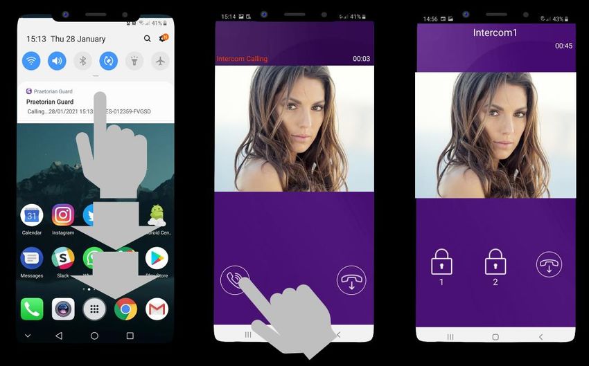
28 | P a g eAnswering on Android
This will launch the app
Swipe down to reveal Press the appropriate
the android and reveal the answer
lock icon (depending
notifications and press screen. Press the icon
on which relay your
shown to answer the
the Praetorian installer has connected
call if you wish to
notification to the gate or door)
speak to the visitor
29 | P a g eAnswering on iOS (Apple)
Swipe the Phone will now launch app. Press icon to
Press “VIEW”
notification left answer
Note: Various versions of IOS and Android OS will have different notification acceptance
techniques. Please refer to online support for your device if needed.
TIP: Make sure ringer switch is
ON and volume is turned up.
Praetorian Guard
TIP: If you don’t get notifications
TIP: If there is no voice from the speaker at the
then check settings/notifications
gate, check the iphone microphone permissions in
and select the app.
Settings > Privacy / Microphone
30 | P a g ePHASE 4
Installation
(Only to be done after the unit is successfully
proven to be operating on the network during
setup on phase 3.)
31 | P a g eHow to Achieve & Maintain IP55 Rating
The IP55 rating attached to this unit is only achieved if the below steps have been
followed. This is to prevent any unwanted water and/or bug ingress that can cause
various issues with functionality and will void warranty if not followed.
Step 1 – Mount to location
Use the pre-drilled mounting holes and
cable cut outs to connect the intercom to
the mounting option choosen.
Step 2 – Seal unit
Seal all mounting or cable cut outs by using
sealant such as silicone.
Ensure that any products being used are safe to use as
some products can cause damage to the unit and/or the
mounting location.
If surface mounting seal around the back box
especially when used on an uneven surface.
Step 3 – Close unit
Ensure the security screws or
cam lock is adequately closed
to ensure a correct seal.
Architectural,
Pedestal Design Imperial & Modular Flush Design
Design
32 | P a g eInstallation (Wi-Fi)
Mount the antenna as high
as possible and away from
Intercom wall/pillar obstructions such as
mounted vehicles, shrubs and trees
to maximise signal strength.
Do NOT mount antenna at
ground level.
Pedestal
mounted
version
Antenna mounted
Antenna cable (do not inside gate or fence
cut or join). to improve range.
Longer length options
available.
Installation (LAN Cable)
Run of CAT5/6E Cable
going back to customers
Pedestal router inside property.
mounted
version
MAX DISTANCE 100m (320ft)
This can be extended by using a ethernet cable extender
(purchased separately)
33 | P a g ePower
This intercom comes with a 24v dc power supply. The intercom requires up to 2 amps peak demand at times,
therefore power cable is of extreme importance.
WIFI Antenna (Connect Intercom
to Main PCB) (Install at desired height)
DC Power
Cable
Up to 2 meters (6 feet) use minimum 0.5mm2 / 22 gauge cable.
PSU Enclosure
(Sold Separately)
Up to 4 meters (12 feet) use minimum 1mm2 / 20 gauge cable.
Up to 8 meters (25 feet) use minimum 1.5mm2 / 18 gauge cable
Solar Power
You can use solar power if required. You will require a DC voltage regulator applied at the gate board end as
the voltage output can vary and cause too high a voltage, which will damage the intercom if over the 26v DC.
Our systems would require as a minimum a 30W of solar panel capacity and 10ah battery capacity for our
intercoms.
Power
Consumption:
Standby = 96mA
Calling Out = 500mA
34 | P a g eLAN Cable Setup Example
Note: You can run CAT5 cable up to 100m (320ft)
for full connection.
Further distances can be achieved with additional
equipment.
WiFi Setup Example
Note: Up to 60m using 2.4GHz with an average home
router and clear line of sight.
Further distances can be achieved with advanced
additional equipment.
If looking to use 5.8GHz a different antenna will be
required. You can expect to achieve approx. 15m
with clear line of sight using this frequency.
35 | P a g eWiring Example
Antenna
Serial
Number
Ethernet
Socket
Reset
SD CARD
8GB SD card
B +M S Relay Relay
1 2 Speaker Volume
24V 0V N/O C1 N/C N/O C2 N/C EG GND
Exit button
24v DC
From PSU
Magnetic lock
Gate controller N/C button
12v DC (not
supplied)
Note: When the exit button is pressed it will
trigger relay 1 for the pre-programmed time
in the app. (Default is 1 second)
36 | P a g eConnecting Slave Devices
*Keypad module required
CAT5 (30ft max) Optional Slave
300ft if device powered Keypad
separately
IN
1 2 3 24v
Optional
Keypad To next
device
1 2 3 24v
OUT
IN
OUT
1 2 3 24v
IN To next
device
OUT
OUT
Optional 1 2 3 24v
Prox reader IN
Note: Optional Slave
Up to a total of 8 devices can be connected to the one SIM Prox Reader
module.
All keypads will be programmed with the same codes as the
main unit.
All Prox units will store the same Prox cards.
Power slave devices separately for longer distances.
37 | P a g eAdding Additional APP Users
Additional users MUST be added with individual usernames. Do NOT use the same username.
Step 1
On the Admin user phone, create a new username and password for any additional phones
which you wish to add, as follows.
Admin Device!
Create a NEW
Press the PLUS username &
icon to add a user password
Step 2
On a new phone or tablet, perform the following steps to log on to the intercom with the details
which have been created by the ADMIN phone above…
NEW Device!
Note: Maximum 8 separate users and devices. Each device connected must be logged in with
their own user account for correct operation. Only ADMIN can change critical system settings
of the intercom.
38 | P a g eSound,
Serial Volumes and Speech
Number
This intercom is capable of full duplex speech, which means two people can have a conversation
and appear to speak at the same time. Since various manufacturers of android phones, iPhones
and tablets all differ in acoustic performance, and different users may require varying levels of
volume on their own handset, it may be possible to setup some devices in full duplex mode, but
others may need to beEthernet
set in half duplex mode (phone user will press to talk). This may also be
required if a phone is inSocket
a particularly noisy environment, or the intercom is located near a busy
main road with high levels of traffic noise.
(RJ45)
RESET
Intercom Volume SD CARD
8GB
B +M S Relay Relay
1 2
Suggest 80%
24V 0V N/ O C1 N/C N/ O C2 N/C EG GN D
MAX volume
Intercom & Device Sound Options
Choose the speech option which best suits
the individual and the device being used.
Suggest 70% MAX volume.
Note: If the phone volume is too high an echo may be heard by the visitor at the intercom.
39 | P a g eUsing Keypad Codes
Ensure you program a keypad code in the app first then follow the steps below to use
them on the keypad to gain entry.
Enter pre-programmed 4-6
digit code., followed by the *
key to confirm
Tip: Press * to confirm keypad code
40 | P a g ePHASE 5
Advanced Setup
(Only to be done after the unit is successfully
proven to be operating on the network after
installation)
41 | P a g eFeature Shortcuts
Add / delete
Activity Log
proximity cards / tags
Add / delete Turn on / off
keypad codes. notifications on events.
Settings Overview
Standard
Features
Advanced
Features
42 | P a g eStandard Features
Edit Intercom
details
Ring tones of in-app call (unable Check APP version Add a new device ID
to change notification tone)
Check current
system firmware
Add, edit or Adjust relay Adjust intercom time
delete users trigger times (daylight saving)
Wi-Fi settings
Adjust maximum Adjust maximum Adjust maximum
monitoring time talking time ringing time
Reboot Simplex / duplex
intercom audio selection
43 | P a g eEdit Intercom Details
Change the name of the intercom
Intercom ID cannot be changed. Follow the add as
a new device steps if ID is incorrect.
Change the username
Change the password
Add a New Device ID
Name the intercom
Intercom ID can be added manually or auto filled by
using the ‘SEARCH INTERCOM ID IN LAN’ button
Enter username, setup by the ADMIN
Enter password, setup by the ADMIN
If you are connected via LAN you
can pull the ID via the network
44 | P a g eRingtones of In-app Call
Choose your
preferred ringtone
for calls while
inside the app.
Note: The default call notification tone heard while not in the app cannot be changed.
Check APP version
App Version
Note: Check the Google Play or the Apple app store to ensure you are using the most recent version.
45 | P a g eCheck Intercom Firmware
Intercom Firmware
Version
Note: See ‘Firmware Updates’ for more info.
Add, Edit or Delete Users & Logins
Add New User
Edit User
Delete User
Username
Password
Cancel
Note: Administrator account cannot be Save
deleted but the password can be edited
by selecting the pencil icon to the user.
46 | P a g eAdjust Relay Trigger Times
Save Settings
Relay 1 Trigger times
Relay 2 Trigger times
Adjust Intercom Time
Save Settings
NTP Server
Enable/Disable Daylight Saving
Sync to device timezone
47 | P a g eWi-Fi Settings
SSID currently connected to
Search for WiFi Networks.
See WiFi Setup for more details
Note: If showing POOR signal level, STOP!
You must reposition the antenna or look at
alternative options to connect the intercom
to the network.
Adjust Maximum Monitoring Time
Save Settings
Change the length of time you can
view the camera direct from the app
48 | P a g eAdjust Maximum Talking Time
Save Settings
Change the length of time you can
talk when a call is answered before
the call disconnects.
Adjust Maximum Calling Time
Save Settings
Change the length of time
your intercom calls for.
Note: If you do not have a good
data signal (i.e. 4G or WIFI) on the
receiving device it may stop you
from receiving the call correctly.
Note: All devices connected will
receive a notification at the same time.
49 | P a g eReboot Intercom
Soft Reboot the intercom
Simplex / Duplex Audio Selection
Save Settings
Soft Reboot the intercom
Soft Reboot the intercom
Soft Reboot the intercom
Note: If the volume on the device is too high or is in a
noisy environment, it may cause echo or clipping in
audio. If this occurs, you can turn down the device’s
volume or switch to one of the simplex audio options.
50 | P a g eAdvanced Feature Overview
Auto opening
Notifications on of gates on
weekly Select resolution View activity
gate/door opening
schedule of camera stream log
& motion sensor
Voicemail option Motion
Keypad codes Prox cards
for missed callers detection option
Notifications
Enable/Disable app push notifications.
(Default = OFF)
Relay Trigger – Anytime the relay is
triggered a notification will be sent.
This will affect PROX ID’s, Keypad
Codes & In-App Relay triggers.
Relay 1 = Entrance 1
Relay 2 = Entrance 2
Motion Sensor – Anytime the motion
sensor detects movement a
notification will be sent.
Note: Motion Sensor feature needs Enabled too for
this to work as expected. See Motion Sensor Settings.
51 | P a g eAuto opening of gates on weekly schedule
Save Settings
Relay Action
Time of Action
Day(s) for relay action to happen
Note: If a latched command is used then an unlatch
will be required to return the relay to its normal state.
Date & Time settings of the intercom must be
accurate for correct operation.
Select resolution of camera stream
Choose what resolution to use
when your device is connected
to WIFI & 4G.
Note: Data charges may apply if you
exceed your personal allowance.
52 | P a g eActivity Log
The log shows the most recent events which have
occurred on the intercom. Some examples are shown.
Some of the events capture images, or video from
calls and can be played back by pressing the icons to
the right.
Call received.
Keypad code entered.
Timed auto open event.
Note: SD card must be inserted into the slot on the PCB for this feature to operate
correctly.
The log will show the last 100 events. Older events can still be retrieved via a microSD
reader.
See page 10 for the SD card specifications.
53 | P a g eKeypad Codes
*Keypad models only
There are 3 types of keypad code options which can be entered
as shown.
1. 24/7 codes which work all of the time. (max 100)
2. Time restricted codes which only work on pre-set
times and days. (max 100)
3. Auto Expire codes which are temporary. (max 100)
Note: Press the * button to confirm the keypad code after entering it.
1. 24/7 Codes
(max 100)
2. Time Restricted Codes Enter Name & Select
(max 100) which relay to trigger
& how long the relay
will trigger for. Then
enter a keypad code
& press SAVE
3. Auto Expire Codes
Enter Name & Select (max 100)
the days & time a
code should work,
then enter the code &
press SAVE
Note: Time Restricted & Auto-Expire options are
only available for Relay 1. The relay time is
controlled via the main relay settings. Enter Name & Select
how long the code
24/7 options have a relay time specific to each should be valid for,
code. then enter the code &
press SAVE
54 | P a g ePROX Cards/Tag IDs
*PROX models only
There are 3 types of PROX ID options which can be entered as
shown.
4. 24/7 ID’s which work all of the time. (max 100)
5. Time restricted ID’s which only work on pre-set
times and days. (max 100)
6. Auto Expire ID’s which are temporary. (max 100)
1. 24/7 ID’s
(max 100)
2. Time Restricted ID’s
(max 100)
Enter Name & Select
which relay to trigger
&how long the relay
will trigger for. Then
enter the card ID &
press SAVE
3. Auto Expire ID’s
Enter Name & Select (max 100)
the days & time an ID
should work, then
enter the card ID &
press SAVE
Note: Time Restricted & Auto-Expire options are
only available for Relay 1. The relay time is
Enter Name & Select
controlled via the main relay settings.
how long the ID
24/7 options have a relay time specific to each should be valid for,
code. then enter the card ID
& press SAVE
55 | P a g eVoicemail Option for missed Callers
When voicemail is activated if a call is not answered
then an audio message will play to ask the visitor to
leave a message. A 20 second video recording can be
viewed in the events log.
Enable/Disable Voicemail feature
Note: SD card must be inserted into the slot on the
PCB for this feature to operate correctly.
The log will show the last 100 events. Older events
can still be retrieved via a microSD reader.
Motion Detection Option
When motion sensor is activated a small video clip will
record anytime the system picks up movement in the
area.
The distance is fixed at max 5m with the option to
choose how sensitive the sensor is. The higher the
sensitivity the easier it will be to trigger the sensor to
record.
Enable/Disable Voicemail feature
Change sensor sensitivity
56 | P a g eTroubleshooting
It is worth remembering that when you install this intercom, you are literally only supplying 25% of
the overall system. The other 75% already exists with the customer. Namely the router, the Wi-Fi
network, and the phones or devices.
Anything can go wrong with any part of that entire system. Therefore, it is a useful exercise to
attempt to prove to the customer that the intercom hardware is working and operational before
attempting to diagnose the root cause, especially when connected wirelessly to a network.
If the intercom is connected via Wi-Fi to the network, it is very useful to press and hold the code
button on the board, then connect the phone DIRECTLY to the BELL Wi-Fi network (must be
within Wi-Fi range of intercom). Open the app and show the customer that when the phone is
connected directly to the intercom, there is video and two-way speech. The job is then to find out
what part of the installation or overall system is causing the problem since the intercom hardware
has been proven as operational.
We can say without doubt that when we do get hardware failures, the above process will not work,
and you will not get video and voice to the phone in a direct connection like this.
Below are the most common causes of problems with installs, starting with the most common first.
Symptoms caused Problem/error Solution
App showing offline status, video Wi-Fi too weak at gate Increase the height of the antenna if
image shows “fetching, long lag possible, install a Wi-Fi booster either
on calls, intermittently showing inside the house near the front of the
online/offline, delayed push property, or a loft or eaves mounted
notifications. external Wi-Fi booster, or install a
CAT5 cable from the intercom to the
router.
Delayed push notifications, Wrong power cable (too Change the power cable to
video lag, voice problems, thin) installed from 24v specifications shown within this
freezing, relays not opening the adaptor to the intercom, or manual.
gate. power adaptor too far from
intercom.
Lagging video or audio, delayed Too many devices on home Turn off as many other devices as
notifications, status showing network possible, reboot the router and then try
intermittently online/offline, no or again. If the unit works, it proves to the
randomly operation of push customer that their router needs to be
notifications. upgraded to handle the demand.
Intercom works well sometimes Several Wi-Fi networks The intercom is jumping between
and not well other times. The using the same SSID networks depending on traffic and
Wi-Fi signal strength on the app other devices connected to the same
Wi-Fi screen can sometimes be node. It is advisable to change the
strong and other times is weak. SSID name of the Wi-Fi network
closest to the intercom to something
individual.
Offline status. Will not connect to Incorrect Wi-Fi password Try process again. Check the same
the network entered during setup Wi-Fi password works on your phone
(forget the network and re-connect
using the same password).
Can randomly display status “id Additional user added When an additional user was being
already in use” incorrectly. added, the process was done
incorrectly. Additional users MUST be
added by the admin device first, with
57 | P a g eseparate usernames created for each.
The new usernames and passwords
must be used by the new devices as
shown in this manual to logon to the
intercom.
App shows online when phone is Commercial firewall This will be a job for the IT provider for
in the same network but offline the business. A port will need opened
when phone on 3G/4G or on a to allow P2P and PUSH notification
remote Wi-Fi network, App traffic to pass through the firewall.
works fine remotely to view Recommended unassigned ports
gates but push notifications are which your network administrator can
not working at all. open are 6806, 6809 and 9123, 9124.
App shows online status locally Insufficient upload speed This will need discussed with the ISP /
and when phone is remote, but broadband provider.
push notifications may be
delayed, or video lag, or
showing “fetching” on video
screen.
Intercom is online and working Incorrect time. Cycle to the settings menu and
even through the application, but navigate to the clock settings and
I am receiving no notifications press “sync phone time” to sync the
even for calls! I have checked current time from the cellphone. This
my Wi-Fi/Ethernet and the should only ever need done once as
intercom meets minimum the time is pulled from the server.
requirements
I think my intercom is not Firmware/software bug. Firstly ensure there is no network or
functioning correctly. site related issues. To do this you can
connect directly to the system hotspot
while in proximity of the unit and if the
system operates fine then the local
network and/or site specific issues are
causing the problem.
If the same issue occurs then a soft
reboot can be completed by cycling to
the settings menu and navigate to the
power icon, pressing this will initiate a
soft reboot. This soft reboot will
remove any open communications or
potential non-functioning features to
be re-enabled.
If this issue persists a hard reset may
need to be performed. Access inside
the panal is required and this will
delete all current data programmed to
the intercom and remove any
additional users etc.
If this still does not fix the problem this
this would suggest a hardware fault.
Please contact technical support.
58 | P a g eApp Updates
We will continually monitor the app’s performance and will release updates to enhance
the users experience and/or fix any issues that arise overtime. These updates will be
available via the iOS app store or the Android Play store.
Firmware Updates
Firmware updates will be released to fix any bugs or to add additional features where
possible throughout the products lifetime.
The most recent firmware version your system is using can be found by using the app
The most recent firmware version will be available via the manufacturer website along
with details of any changes made. The updates will be sent to all devices when it is
released and if your system is ONLINE at the time it will update with no interaction from
the user.
If you find your intercom is on an older firmware and may have missed the automatic
rollout you can contact the manufacturer technical support via phone or live chat who
can perform the update manually via a remote desktop application.
Extra Resources
Find all our support resources on our website or scan the QR code below.
www.aesglobalonline.com
59 | P a g eIntercom Maintenance
Bug ingress is a common issue in unit failures. Ensure that all components are sealed
accordingly and check occasionally. (Do not open the panel in the rain / snow unless
correctly equipped to keep the internals dry. Ensure the unit is securely closed after
maintenance)
If you have an AB, AS, ABK, ASK callpoint it will have silver edges which are marine
grade stainless steel so in normal weather conditions should not rust however it can
dull or discolor over time. This can be polished with a suitable stainless-steel cleaner
and cloth.
Environmental Information
The equipment that you bought has required the extraction and use of natural
resources for its production. It may contain hazardous substances for the environment.
In order to avoid the dissemination of those substances in our environment and to
diminish the pressure on the natural resources, we encourage you to use the
appropriate take-back systems. Those systems will reuse or recycle most of the
materials of your end-of-life equipment.
The crossed-bin symbol marked in your device invites you to use
those systems.
If you need more information on the collection, reuse and recycling systems, please
contact your local or regional waste administration. You can also contact AES Global
Ltd for more information on the environmental performances of our products.
Ingress
We recommend sealing all entry holes for prevention of insects that can
cause issues with a risk of shorting out components.
To maintain the IP55 rating please follow the sealing instructions included.
(also available online)
60 | P a g eWarranty Please note, by installing this product, you are accepting the following warranty terms: 1. The manufacturer’s warranty is a “return to base” 2 year warranty from date of manufacture. This means that any suspected defective components or items are returned to the manufacturer’s agent for investigation and diagnosis and returned at the cost of the customer. 2. The warranty does not cover, nor is the manufacturer or agent responsible for any of the following whatsoever: Storm damage, lightning or surge damage, flooding, accidental damage, vandalism or deliberate damage, un-explained corrosion or unusually harsh environments, failure of telephone networks, future un-interoperability between the product and network providers which cause mal-function due to changes implemented by the phone providers after manufacture of the product, or that which is outside of control of the manufacturer (e.g. 2G, 3G switch off, removal or inability to obtain VOLTE service), and damage due to not proper installation. 3. The manufacturer in no way accepts liability for any of the following incurred due to a product defect: Cost of attending site, inconveniences, labour rates, time lost, loss to or damage to property, security breaches, late payment clauses or breaches of any contracts between the installer and the client. 4. This is a profession install product only. The product is a component of an overall system. Therefore, it is the responsibility of the installer to certify the safety and compliance of the overall finished system. As soon as this product is fixed to another item, or connected to another third-party device, then the product has been modified, and compliance with local regulations in the country of install is strictly the responsibility of the installer. 5. Re-stocking fees may apply to items returned that are found to be non-defective. Complete units will also attract a re-stocking fee if returned for credit, regardless if a defect is discovered or not. Re-stocking fees may vary depending on the condition of the item being returned, and whether it can be determined as in brand new condition. The warranty terms do not entitle customers to an automatic full refund. For more details on returns procedures and re-stocking fees, contact the agent. 6. Items with physical signs of surge damage are not covered by warranty. Items with visible signs of surge damage will only be covered by warranty if photographic evidence is provided from site, showing surge protection has been installed. Full warranty terms and conditions available upon request to AES Technical Department. 61 | P a g e
LEFT BLANK

62 | P a g e
LEFT BLANK

63 | P a g e
Regulatory Compliance
FCC Id: 2ALPX-WIFI-IBK
Grantee: Advanced Electronic Solutions Global Ltd
This device complies with Part 15 of FCC rules. Operation is subject to the following two
conditions: (1) this device may not cause harmful interference, and (2) this device must accept
any interference received, including interference that may cause undesired operation.
Output power listed is conducted. This device must be installed to provide a separation distance
of at least 20 cm from all persons and must not be co-located or operating in conjunction with any
other antenna or transmitter. End-users and installers must be provided with antenna installation
instructions and transmitter operating conditions for satisfying RF exposure compliance. This
device has 20MHz and 40 MHz bandwidth modes.

          EU-RED Declaration of Conformity
Manufacturer: Advanced Electronic Solutions Global Ltd
Address: Unit 4C, Kilcronagh Business Park, Cookstown, Co Tyrone, BT809HJ, United Kingdom
We/I declare, that the following equipment (Video intercom), part numbers:
WiFi-iBK, WiFi-iB, WiFi-ABK, WiFi-AB, WiFi-BD, WiFi-BEK,
WiFi-BEik, WiFi-Bei, WiFi-BFT-KPAD
Complies with the following essential requirements:
EN 301 489-1 V2.2.0 (2017-03) (Electro-Magnetic compliance)
EN 301-489-17 V3.2.0 (2017-03) (Electro-Magnetic compliance)
EN 62479:2010 (Maximum output power)
EN60950-1:2006+A11:2009+A1:2010+A12:2011+A2:2013 (Electrical Safety)
This product is not a complete product until fully installed. It is therefore considered a component
part of an overall system. The installer is responsible to check that the end installation complies
      with local regulatory requirements. This equipment forms part of a “fixed installation”

                           NEED MORE ASSISTANCE?
                             +44 (0)288 639 0693

64 | P a g e
You can also read