Instruction Manual PSx3xxDP - halstrup walcher
←
→
Page content transcription
If your browser does not render page correctly, please read the page content below
Instruction Manual
                       PSx3xxDP

                                 halstrup-walcher GmbH

                                 Stegener Straße 10
                                 D-79199 Kirchzarten, Germany

                                 Phone:   +49 (0) 76 61/39 63–0
                                 Fax:     +49 (0) 76 61/39 63–99

                                 E-Mail: info@halstrup-walcher.com
                                 Internet: www.halstrup-walcher.com

Document 7100.003964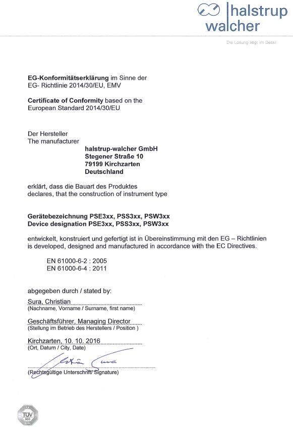
PSx3xxDP Instruction Manual

            Table of Contents

1          Safety precautions ........................................................................................................... 6
    1.1       Appropriate use .............................................................................................................. 6
    1.2       Shipping, assembly, electrical connections and start-up ................................................. 6
    1.3       Troubleshooting, maintenance, repairs, disposal ............................................................ 6
    1.4       Symbols.......................................................................................................................... 7
2          Device description ........................................................................................................... 7
    2.1       Features ......................................................................................................................... 7
    2.2       Installation ...................................................................................................................... 8
    2.3       Disassembly ................................................................................................................. 10
    2.4       Powering the device ..................................................................................................... 10
    2.5       Pin assignment ............................................................................................................. 10
     2.5.1      Supply voltage connector .......................................................................................... 10
     2.5.2      Round socket for bus ................................................................................................ 11
     2.5.3      Connector for jog keys .............................................................................................. 11
     2.5.4      Electrical grounding................................................................................................... 11
    2.6       Setting the device address and terminating resistors .................................................... 11
    2.7       LED status .................................................................................................................... 12
    2.8       Using the bus to set the address .................................................................................. 12
    2.9       Using the parameter module to set the address (firmware version 8) ........................... 13
3          Jog key operation .......................................................................................................... 13
    3.1       Connecting the jog key inputs ....................................................................................... 13
    3.2       Using the control unit to activate the jog keys ............................................................... 14
    3.3       Direct positioning using the jog keys ............................................................................. 14
    3.4       Incremental manual operation ...................................................................................... 14
    3.5       Incremental operation ................................................................................................... 14
4          Start-up ........................................................................................................................... 15
    4.1       Setting the reference position ....................................................................................... 15
    4.2       Positioning sequence.................................................................................................... 15
    4.3       Positioning sequence (without reference loop).............................................................. 16
    4.4       Reverse drive ............................................................................................................... 16
    4.5       Devices with optional snap brake.................................................................................. 17
    4.6       Devices with optional holding brake .............................................................................. 18
5          Interface .......................................................................................................................... 19
    5.1    Status byte configuration .............................................................................................. 19
     5.1.1 Target position reached............................................................................................. 19
     5.1.2 Drive running............................................................................................................. 19
     5.1.3 Motor supply voltage OK ........................................................................................... 20
     5.1.4 Ready ....................................................................................................................... 20
     5.1.5 Hardware error .......................................................................................................... 20
     5.1.6 Positioning run aborted ............................................................................................. 20
     5.1.7 Jog key, down ........................................................................................................... 20
     5.1.8 Jog key, up................................................................................................................ 20
     5.1.9 Temperature too high ................................................................................................ 20
     5.1.10    Drag error .............................................................................................................. 20
     5.1.11    Invalid target/parameter value ............................................................................... 20
     5.1.12    Positioning error .................................................................................................... 21
     5.1.13    Manual rotation ...................................................................................................... 21

                                                                        2
PSx3xxDP Instruction Manual

 5.1.14    No supply voltage available to motor ..................................................................... 21
 5.1.15    Upper range limit ................................................................................................... 21
 5.1.16    Lower range limit ................................................................................................... 21
5.2    Actual position .............................................................................................................. 21
5.3    Control byte configuration ............................................................................................. 21
 5.3.1 Confirmation.............................................................................................................. 22
 5.3.2 Release bit ................................................................................................................ 22
 5.3.3 Manual run release ................................................................................................... 22
 5.3.4 Run with no reference loop ....................................................................................... 22
 5.3.5 Set value for reference position ................................................................................. 22
 5.3.6 Set and save reference position ................................................................................ 22
 5.3.7 Accept and proceed to position ................................................................................. 22
 5.3.8 Manual run, down...................................................................................................... 22
 5.3.9 Manual run, up .......................................................................................................... 22
5.4    Target position .............................................................................................................. 23
5.5    Parameters ................................................................................................................... 23
 5.5.1 Direction of rotation ................................................................................................... 24
 5.5.2 Direction of travel ...................................................................................................... 24
 5.5.3 Position correction..................................................................................................... 24
 5.5.4 Jog key operation ...................................................................................................... 24
 5.5.5 Hardware resolution .................................................................................................. 24
 5.5.6 Software resolution ................................................................................................... 25
 5.5.7 Positioning window.................................................................................................... 25
 5.5.8 Max. run distance, positive ........................................................................................ 25
 5.5.9 Max. run distance, negative ...................................................................................... 25
 5.5.10    Target rpm, positioning run .................................................................................... 25
 5.5.11    Target rpm, manual run ......................................................................................... 25
 5.5.12    Max. rpm, left ......................................................................................................... 25
 5.5.13    Max. rpm, right....................................................................................................... 25
 5.5.14    Max. torque ........................................................................................................... 25
 5.5.15    Max. torque, left ..................................................................................................... 26
 5.5.16    Max. torque, right................................................................................................... 26
 5.5.17    Max. starting torque ............................................................................................... 26
 5.5.18    Duration of starting torque ..................................................................................... 26
 5.5.19    Holding torque ....................................................................................................... 26
 5.5.20    Drag error .............................................................................................................. 26
 5.5.21    Min. rpm for detecting an obstacle ......................................................................... 26
 5.5.22    Time required to detect an obstacle ....................................................................... 26
 5.5.23    Wait time between runs ......................................................................................... 26
 5.5.24    Min. supply voltage ................................................................................................ 27
 5.5.25    Filter value for voltage monitoring .......................................................................... 27
 5.5.26    Loop length............................................................................................................ 27
 5.5.27    Jog key increment size .......................................................................................... 27
 5.5.28    Jog key pause ....................................................................................................... 27
 5.5.29    Factor for ramp length ........................................................................................... 27
 5.5.30    Limiting temperature .............................................................................................. 27
 5.5.31    Reference position MSW ....................................................................................... 27
 5.5.32    Reference position LSW ........................................................................................ 28
 5.5.33    Production date ..................................................................................................... 28
 5.5.34    Serial number ........................................................................................................ 28
 5.5.35    Device type ............................................................................................................ 28
 5.5.36    Software version .................................................................................................... 28
 5.5.37    Hardware version .................................................................................................. 28
 5.5.38    Device temperature ............................................................................................... 28
 5.5.39    Actual rpm ............................................................................................................. 28
 5.5.40    Max. actual torque (current) ................................................................................... 28

                                                                  3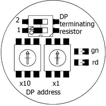
PSx3xxDP Instruction Manual

     5.5.41   Run time MSW ...................................................................................................... 28
     5.5.42   Run time LSW ....................................................................................................... 28
     5.5.43   Drag position ......................................................................................................... 28
     5.5.44   Motor supply voltage ............................................................................................. 29
     5.5.45   Motor current ......................................................................................................... 29
     5.5.46   Supply voltage for control unit................................................................................ 29
     5.5.47   Error code.............................................................................................................. 29
    5.6    Changing parameter values .......................................................................................... 29
6          Backing up parameter data and the error memory ...................................................... 30
7          Technical data ................................................................................................................ 31
    7.1       Drive speed and torque PSE ........................................................................................ 31
    7.2       Drive speed and torque PSE and PSS ......................................................................... 31
    7.3       Drive speed and torque PSW ....................................................................................... 32
    7.4       Ambient conditions ....................................................................................................... 32
    7.5       Electrical data ............................................................................................................... 33
    7.6       Physical data ................................................................................................................ 34
8          Certificate of Conformity .............................................................................................. 35

                                                                       4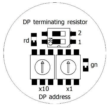
PSx3xxDP Instruction Manual
Purpose of instruction manual
This instruction manual describes the features of the PSx 3xxDP positioning systems and
provides guidelines for their use.
Improper use of these instruments or failure to follow these instructions may cause injury
or equipment damage. All individuals responsible for operating these instruments must
therefore be properly trained and aware of the hazards, and must carefully follow these
operating instructions and the safety precautions detailed within. Contact the
manufacturer if you do not understand any part of this instruction manual.
Handle this manual with care:
It must be readily available throughout the lifecycle of the instruments.
It must be provided to any individuals who assume responsibility for operating the
instrument at a later date.
It must include any supplementary materials provided by the manufacturer.
The manufacturer reserves the right to continue developing this instrument model without
documenting such development in each individual case. The manufacturer will be happy
to determine whether this manual is up-to-date.
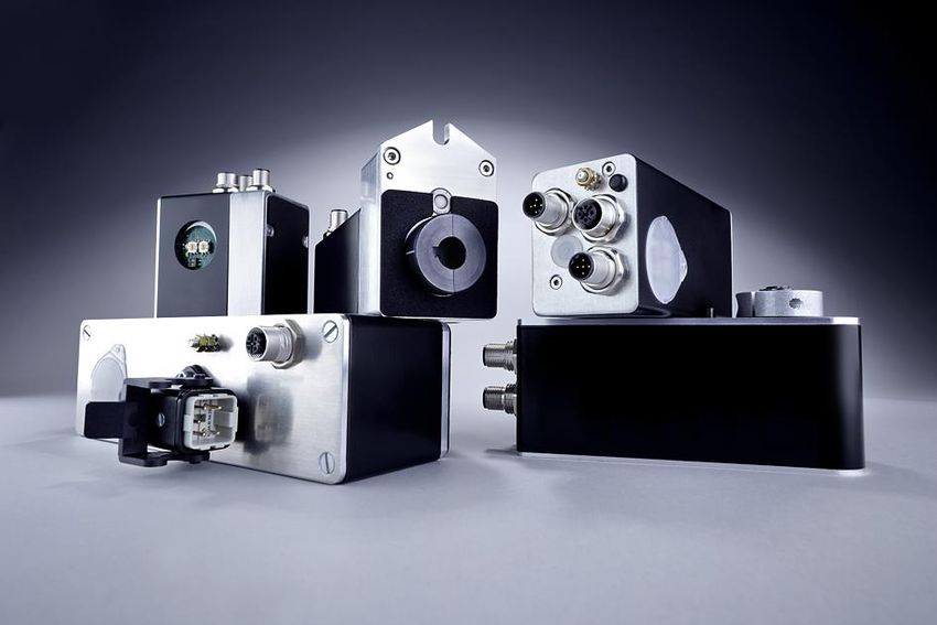
Conformity
This instrument corresponds to the state of the art and meets all legal requirements
set forth in EC directives as evidenced by the CE label.
© 2006, 2007, 2014, 2015, 2016, 2017, 2019, 2020
The manufacturer owns the copyright to this instruction manual. This manual contains
data, instructions and drawings pertaining to the features and usage of these instruments;
copying this manual in part or in full or distributing it to third parties is prohibited.
5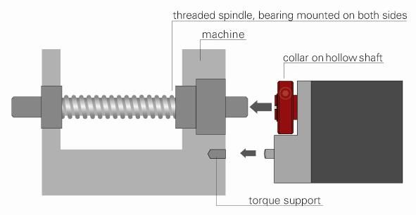
PSx3xxDP Instruction Manual

  1    Safety precautions
1.1   Appropriate use

      Positioning systems are especially suitable for automatically setting tools, stops or
      spindles for wood-processing equipment, packing lines, printing equipment, filling units
      and other types of special machines.

      PSx3xxDP positioning systems are not stand-alone instruments and may only be
      used if coupled to another machine.

      Always observe the operating requirements – particularly the permissible supply voltage –
      indicated on the rating plate and in the “Technical data” section of this manual.

      The instrument may only be handled as indicated in this manual. Modifications to the
      instrument are prohibited. The manufacturer is not liable for damages caused by improper
      use or failure to follow these instructions. Violations of this type render all warranty claims
      null and void.

1.2   Shipping, assembly, electrical connections and start-up

      Only technical personnel who are appropriately trained and authorized by the operator of
      the facility may assemble the instrument and set up its electrical connections.

      The instrument may only be operated by appropriately trained individuals who have been
      authorized by the operator of the facility.

      Specific safety precautions are given in individual sections of this manual.

1.3   Troubleshooting, maintenance, repairs, disposal

      The individual responsible for the electrical connections must be notified immediately if
      the instrument is damaged or if errors occur.

      This individual must take the instrument out of service until the error has been corrected
      and ensure that it cannot be used unintentionally.

      This instrument requires no maintenance.

      Only the manufacturer may perform repairs that require the housing to be opened.

      The electronic components of the instrument contain environmentally hazardous materials
      and materials that can be reused. For this reason the instrument must be recycled in
      accordance with the environmental guidelines of the jurisdiction in question once it has
      been taken permanently out of service.

                                                 6
PSx3xxDP Instruction Manual
1.4 Symbols
The symbols given below are used throughout this manual to indicate instances when
improper operation could result in the following hazards:
This warns you of a potential hazard that could
WARNING : lead to bodily injury up to and including death if
the corresponding instructions are not followed.
This warns you of a potential hazard that could
CAUTION : lead to significant property damage if
corresponding instructions are not followed.
This indicates that the corresponding information
INFORMATION : is important for operating the instrument properly.
CAUTION : This indicates possible hot surface.
2 Device description
2.1 Features
The PSx3xx positioning system, an intelligent, compact, complete solution for positioning
auxiliary and positioning axes, consists of an EC motor, gear power amplifier, control
electronics, absolute measuring system and Profibus DP interface. The integrated
absolute measuring system eliminates the need for a time-consuming reference run.
Connecting to a bus system simplifies the wiring. A hollow shaft with adjustable collar
makes assembly quite simple. The positioning system is especially suitable for
automatically setting tools, stops or spindles for wood-processing equipment, packing
lines, printing equipment, filling units and other types of special machines.
PSx3xx positioning systems convert a digital positioning signal into an angle of rotation.
7PSx3xxDP Instruction Manual
2.2 Installation
Hollow shaft:
The PSx3xx is mounted on the machine by sliding it with the hollow shaft onto the spindle
to be driven and fixing it with the clamping ring (recommended shaft diameter 8 h9 or 14
h9; tightening torque of the clamping ring screw with 3 mm hexagon socket: 1.5 Nm).
The depth of the hollow bore is 20 mm. For optimum operation, the pin of the
shaft to be driven should correspond to this depth. Depending on the operating
situation, significantly shorter pins (< 16 mm) may cause damage to the PSx3xx.
When mounting the PSx3xx, it should only be pushed on until the foam rubber
plate lies evenly on the bottom of the machine or is compressed to approx. half
its thickness. Under no circumstances may the PSx3xx "hard" be screwed to the
machine without an air gap.
The rotation lock is made via the pin (in the picture below the hollow shaft) into a suitable
bore as rotary torque support. This hole must be slightly larger than the diameter 6 h9 of
the pin. An oblong hole or slot with a slightly larger width (recommended: 6.05...6.10 mm)
than the dimension of the pin diameter is optimal. The backlash when changing the
direction of rotation has a direct influence on the positioning accuracy and can lead to
damage to the PSx3xx with very large backlash (a few mm) due to the impact load.
The PSx3xx must have a little gap on all sides when mounted, as it can move
axially and/or radially during positioning if the hollow shaft and solid shaft are not
100% aligned. This "staggering" is not a defect of the PSx3xx and also has no
influence on the function, as long as it can move freely.
8PSx3xxDP Instruction Manual
Versions with higher torques (from 10 Nm):
Here the force connection is made via a feather key DIN 6885-A5x5x12.
The clamping ring is not freely rotatable but consists of two halves, the fixed part of the
hollow shaft and the loose clamping clamp. The keyway is located in the half that is fixed
to the output shaft. When sliding onto the shaft to be driven with the key inserted, its
angular position must be aligned with the keyway in the PSx3xx. After pushing on, the
PSx3xx is fixed with the 2 screws in the flexible clamping ring half. Make sure that both
screws are tightened as equally as possible (tightening torque of the screws with 3 mm
hexagon socket: 1.5 Nm).
The information on torque support applies in the same way as described above.
For PSE30x-14, PSE32x-14, PSS30x-14 and PSS32x-14, the position of the anti-rotation
lock can be set at greater distances by unscrewing the base cover, turning it 180° and
then screwing it back on. When screwing on, make sure that the seal is correctly inserted
in the floor.
For torques > 5 Nm we recommend to choose the greater distance.
Solid shaft:
The PSx3xx is installed on the machine by mounting the drive to the axis to be driven
using a coupling and an intermediate flange.
Under no circumstances may the housing cover be used for the
purpose of the transmission of force.
Underwater usage of the PSW is not allowed
Please consider that the device might have
a hot surface during operation!
9PSx3xxDP Instruction Manual
2.3 Disassembly
To remove the PSx3xx from the shaft, release the clamp (for versions with hollow shaft
the clamping ring) and pull the PSx3xx off the shaft. If possible, the PSx3xx should only
be pulled axially. Excessive bending back and forth can damage the output shaft!
For versions with brake, it is essential to observe the instructions in sections 4.5 and 4.6!
2.4 Powering the device
For motor power use a single fuse with max. 3,5 A for each PSx3xx.
For motor power use a single fuse with max. 10 A for each PSE34xx.
For control power you can use a fuse with max. 2,0 A, so it is
possible to power up to 10 units parallel with one fuse.
It is strongly recommended to separate power cables to the PSx3xx
from other power cables that might have dangerous voltage.
2.5 Pin assignment
Please take care that the mating connectors and the used cables
match the connectors in the PSx3xx and are mounted correctly,
in order to achieve the protection class.
2.5.1 Supply voltage connector
connector pattern assignment type
(external top view)
1. +24V motor PSE/PSS:
2. GND motor M12 (A-cod.); 5-pol.
3. +24V control unit PSW:
4. GND control unit M12 (A-cod.);
5. housing/pressure balance 4-pol. with airtube
1. +24V motor PSE34xx:
2. GND motor HAN4A, Harting
3. +24V control unit
4. GND control unit
5. housing/pressure balance
To prevent the ingression of fluids into the PSW-housing during
cooldown, use a special cable with an airtube for pressure balancing of
your PSW
10PSx3xxDP Instruction Manual
2.5.2 Round socket for bus
1. VP +5V
2. RxD/TxD-N / A line
3. DGND (reference potential M12 (B-cod.); 5-pol.
to VP)
4. RxD/TxD-P / B line
5. shield
Due to the use of 5-pin sockets, only five-wire cables should
be used.
2.5.3 Connector for jog keys
connector pattern assignment type
(external top view)
1. +24V output
(=+24V control in supply M8; 4-pol.
voltage connector)
2. forward key
3. reverse key
4. ground (= GND control unit)
2.5.4 Electrical grounding
Next to the connecting plugs there is a M4 stud bolt. It is recommended to connect the
positioning system with a cable as short as possible to the machine base. The minimum
wire cross section therefor is 1.5mm².
2.6 Setting the device address and terminating resistors
Removing the protective cap provides access to two rotary switches for setting the device
address and a DIP switch to set the terminating resistors.
The rotary switches indicate the tens and ones places of the address selected. A setting
of 01 is the delivery state; the PSx3xx identifies itself using address 1 at the bus.
To activate the terminating resistors both switches must be in position ON (If active,
remove the connection to a following device).
Switch configurations:
PSx30xDP, PSx31xDP-14, PSx34xxDP
PSx31xDP-8, PSx33xDP-14
Psx32xDP,
PSx31xxDP
11PSx3xxDP Instruction Manual
Important: Always replace the protective cap after setting the address. This will
prevent dust and contaminants from entering the housing.
2.7 LED status
The red LED indicates the operating status of the Profibus DP.
LED status Meaning
LED remains lit The Profibus DP is not connected or is inactive
LED flashes The instrument has detected data transfer activity on the bus
and identified the transfer rate.
LED is not lit Provided the power supply is switched on, an unlit LED
indicates that the instrument is involved in bus communication.
The green LED indicates the status of the power supply.
LED status Meaning
LED remains lit Power supply of control unit and motor is activ
LED flashes Power supply of the motor is inactive.
LED is not lit Power supply of the control unit is inactive. The status of the
motor supply could not be detected in this case.
2.8 Using the bus to set the address
The Profibus DP can also be used to set the device address, provided the address switch is set
to 00. In the delivery state, the instrument will identify itself using address 100. Various devices
(such as the BW1311 Profibus Master Simulator, see link below) can be used to change this
address. The address is then saved and can be used to communicate with the instrument the
next time it is switched on. The address set at the address switches always takes precedence,
i.e., if an address other than 00 has been set at the address switch, this address is always used
for communication with the instrument.
Link to Profibus Master Simulator BW1311:
http://www.bihl-wiedemann.de/en/products/bus-couplersmaster-simulators/product-
overview-bus-couplersmaster-simulators/l/bw1131.html
Using the address switch instead of the bus to set the Profibus
address offers numerous advantages and more safety. As such,
the bus should only be used for settings when absolutely
necessary.
12PSx3xxDP Instruction Manual
2.9 Using the parameter module to set the address (firmware version 8)
The parameter module can also be used for setting the device address via the bus if no
bus assistant is available for setting the address.
The instrument is projected using the 100 address. Only the 'parameter' module and the
status byte are required. The following settings are set to the device once bus
communication has been initiated.
Parameter index = 126(0x7E)
Parameter data out = 170(0xAA) The 'hardware error' bit is activated in the
status byte
Parameter index = 52(0x34) index DP address
Parameter data in = 0000 set by the instrument
Parameter data out = new DP address
Parameter index = 180(0xB4) index write DP address
Parameter data in = 0000 set by the instrument
Parameter data out = new DP address
The instrument saves the address and resets, after which communication with the
instrument can only occur via the new DP address.
The device address for all halstrup-walcher Instruments is 100 by default. If you wish to
incorporate an address change into an SPS project and do not want to use 100, the
address can be changed for a projected address. In this event, all instruments to be
incorporated into the project must be preset to this address (ex.: 50). The bus then
accepts the device with this address (ex.: 50) for data transfer, introduces the transfer
driver and resets to the new address. The transfer driver and the driver with the address
change function can then be reinstalled.
3 Jog key operation
3.1 Connecting the jog key inputs
The jog key inputs can be used in 2 different wiring modes:
- Connection of potential-free switches
To activate the respective jog key input, the +24V in the jog key plug is connected here.
The GND connection in the jog key plug remains unused.
The 24V output in the jog key plug is internally connected to the +24V control in the
supply plug. It is therefore also possible to connect the jog button inputs directly to the
+24V control potential via switches.
- Connection of an active signal
Here the respective jog key input is connected to the (active) signal connection.
The reference ground of the external active signal should be connected to the GND
connection in the jog key plug.
The +24V output in the jog key plug remains unused.
The GND connection in the jog key plug is internally connected to the GND control in the
power supply plug. If the connected active jog key signal has the same GND potential as
the GND control, the wiring of the GND connection in the jog key plug can be omitted.
13PSx3xxDP Instruction Manual
Connection examples:
potential-free switches active signals e.g. from a PLC
3.2 Using the control unit to activate the jog keys
The jog keys are inactive by default. The jog key status is copied into the status byte, giving the
user the ability to activate jog key functions from the control unit. This only works, however, if the
release has been set in the command byte and the ‘accept and proceed to position’ bit has not
been set. Jog key bits can now be copied from the status byte to the command byte, and the
drive may begin a positioning sequence. This also allows operators to use the control unit as a
means of executing a positioning sequence at one drive using the jog keys of another drive.
3.3 Direct positioning using the jog keys
Direct jog key positioning requires that the jog key function be released, either when setting
parameters or by means of the ‘manual run release’ bit in the command byte. The ‘release’ bit
must be set and the ‘accept and proceed to position’ bit must not be activated. Any jog key input
will now be executed directly by the drive.
3.4 Incremental manual operation
When a jog key is depressed, the drive will move by the distance specified in the ‘jog key
increment size’ parameter. The instrument will then wait for the amount of time specified by the
‘jog key pause’ parameter. If the key remains depressed, the drive will resume operation at
manual speed and will continue until either the key is released or a second key is depressed.
This pause was introduced so that users would have sufficient time to release the key in order to
position the drive in individual increments.
3.5 Incremental operation
Setting the ‘jog key pause’ parameter to zero will suppress manual operation, making it possible
to operate the drive solely in increments.
14PSx3xxDP Instruction Manual
4 Start-up
4.1 Setting the reference position
Once it has been installed, the PSx3xx must be moved to the reference position, either
via the jog keys or with a positioning command. The ‘set reference position' command
(see section entitled ‘Command byte configuration’) is used to set the internal position of
the PSx3xx to zero. This position is saved by the instrument and used as a reference for
all positioning data and ranges.
Position 0000 was assigned to the reference point for firmware version 6 and lower.
Beginning with firmware version 7, however, the reference position is assigned the value
of the module target position. The reference position and assigned position are both
permanently stored in the instrument.
4.2 Positioning sequence
The PSx3xx distinguishes between the following steps of a positioning sequence
(It is assumed that all target positions are approached via forward motion.)
1. New setpoint position is greater than the current actual position: The target is
approached directly.
2. New setpoint position is smaller than the current actual position: The device is moved
further back by the loop length (2a) and the final destination is then approached in
forward motion (2b).
3. New setpoint position is only slightly larger than the current actual position and
previously there was no positioning movement with loop (e.g. a manual movement):
In all cases, the drive approaches the target with a forward movement whose length
corresponds at least to the loop length. In order to achieve this, the drive first moves in
reverse direction (3a), i.e. against the actually desired direction of travel, and then
forwards the actual destination (3b).
The maximum length of this distance is the loop length. If the setpoint differs from the
current actual value by more than the loop length, it is approached directly
15PSx3xxDP Instruction Manual
After reaching the target position, this position is compared with the internal absolute
encoder status. If there is a deviation, the status bit "positionning error" is set.
In the delivery state, the loop length is -250, i.e. each setpoint position is approached in
the forward direction.
4.3 Positioning sequence (without reference loop)
The “positioning without a reference loop” mode is used primarily for moving the small
distances involved in fine adjustments. In this case, each position is approached directly.
This does NOT eliminate any play present in the spindle in question. The PSx3xx internal
gear backlash does not play a role in this case, as position data are acquired directly at
the output shaft.
Underwater usage of the PSW is not allowed.
4.4 Reverse drive
In vertical positioning with spherical roller spindles, pitches of approx. 4..10 mm
and weights from 100 kg, it is possible that the PSx3xx does not consume any
energy from the motor supply when travelling downwards, but rather generates
some. This regenerative operation is permissible under certain conditions. The
energy generated is fed back into the motor supply network via the internal
regenerative circuit and must be drawn off there. The PSx3xx increases the
voltage in the motor supply network until the additional energy is drawn off.
However, the internal protection diode limits this voltage to max. 31 VDC.
The following cases should be considered:
1) If several PSx3xx and/or other loads are connected to the same power supply,
regeneration is possible without any additional measures if several PSx3xx do
not generate power simultaneously. The other devices then act as consumers
of the energy generated by a PSx3xx.
2) If several PSx3xx are to use the regenerative circuit simultaneously, an
overvoltage protection must be provided in the motor supply network.
If a PSx3xx is operated for more than 1-2 seconds in regenerative mode without
consumer of the generated energy, this damages the internal protection diode and the
PSx3xx is defective.
16PSx3xxDP Instruction Manual
4.5 Devices with optional snap brake
The device models PSx30x-14, PSx31x-14, PSx32x and PSx33x can be supplied with an
optional snap brake. This brake prevents the output shaft from turning when the power
supply to the motor is removed, or, if the motor holding torque is too low, to a maximum of
the level of the nominal torque. A small degree of rotation always occurs at the output, i.e.
the brake cannot be used to hold the drive at a defined position (for this purpose the
holding torque may have to be increased).
To release the brake when a run command is transmitted, these devices first wait for a
short time and then run a few increments against the actual direction of movement. The
brake is closing at the end of every run.
Manual turning:
When mounting or dismounting a PSx3xx, it may be necessary to manually turn the
output shaft to a certain position. For this purpose, the actuators are equipped with a
manual adjustment facility:
First, the corresponding cover in the cover must be removed.
Then use a NW3 (PSx31x, PSx33x, or NW4 (PSx30x, PSx32x) hexagon key to
disengage the brake by pressing it down and turn it simultaneously.
An electrical release of the brake via Bus is not possible on its own (without travel job).
Important! To prevent ingress of dirt and dust, the protective cap must be
reattached after setting the address.
A "forced" turning of the drive without disengaging the brake leads to the
destruction of the brake and thus of the drive!
manual adjustement
under cover
PSx31x-14, PSx33x-14 PSx30x-14, PSx32x-14
17PSx3xxDP Instruction Manual
4.6 Devices with optional holding brake
The device model PSE34xx can be supplied with an optional holding brake. This brake
prevents the output shaft from turning when the power supply to the motor is removed, or,
if the motor holding torque is too low.
A run command is not approached immediately but only after a short idle period to tighten
the brake.
The brake releases at the end of every run.
To adjust the drive manually, it is first necessary to remove the corresponding rubber-plug
in the top cover (see drawings at the end of these instructions). The drive can then be
rotated using a hex wrench NW4. This is quite difficult as the operator has to overcome
both any torque present at the output and the force of the friction brake.
The brake is not damaged by manual rotation.
manual adjustement
under cover
18PSx3xxDP Instruction Manual
5 Interface
Modules Format Meaning
status byte 16 bit flags for instrument status
actual signed long 32 bit current actual position in target-value increments
position
command 16 bit flags for controlling the instrument
byte
target signed long 32 bit next position to be achieved in target value
position increments
parameters 8 bit index set and/or read out parameters, indexed
signed int 16 bit data in
signed int 16 bit data out
actual 8 bit index of the parameter that has been read out
index
The status byte provides the user with information on the current status of the PSx3xx.
The actual position indicates the current position at which the positioning unit is located.
The command byte is used to transmit commands to the positioning unit.
The target position is used for transmitting the next position to be reached.
During operation, the parameter module allows users to adjust instrument settings directly (via
the control unit) that could otherwise only be modified when setting parameters.
5.1 Status byte configuration
Bit Hexadec. Meaning
15(MSB) 0x8000 target position reached
14 0x4000 drive running
13 0x2000 motor supply voltage OK
12 0x1000 ready
11 0x0800 hardware error
10 0x0400 positioning run aborted
9 0x0200 jog key, down
8 0x0100 jog key, up
7 0x0080 temperature too high
6 0x0040 drag error
5 0x0020 invalid target / parameter value
4 0x0010 positioning error
3 0x0008 manual rotation
2 0x0004 no supply voltage available to motor
1 0x0002 positive range limit
0(LSB) 0x0001 negative range limit
5.1.1 Target position reached
The drive is at the target position ± the permissible deviation defined by the positioning window.
5.1.2 Drive running
The drive is performing a positioning run.
19PSx3xxDP Instruction Manual
5.1.3 Motor supply voltage OK
The power supply to the motor is higher than the value indicated in the ‘min. supply voltage’
parameter. This bit must be set prior to performing a run. The level of the supply voltage has a
significant effect on the torque and/or motor speed.
5.1.4 Ready
Supply voltages, temperature and target position are all in the permissible range and the drive
can begin operation. An exception here is when the display indicates a hardware error, which the
operator must acknowledge (thereby deleting the error message) before performing the run.
5.1.5 Hardware error
This bit is set if an error is detected during an internal process and causes the drive to stop. The
‘error status’ parameter can be used to determine the source of the error. This bit can be deleted
by temporarily deactivating the release bit in the command byte, an action that causes the error
to be recorded in an internal error memory. The ‘save’ command can be used to save this error
memory in the instrument’s non-volatile EEPROM.
5.1.6 Positioning run aborted
The positioning run has been aborted, either because the release bit was reset or because of an
error.
5.1.7 Jog key, down
This bit indicates that the ‘down’ jog key has been depressed. A manual run can be performed
directly either if the ‘manual run release’ bit in the command byte has been activated or if the
manual run was released when setting parameters and the positioning bit has not been set.
5.1.8 Jog key, up
This bit indicates that the ‘up jog key’ input has been activated (connected to +24V). A manual
run can be performed directly either if the ‘manual run release’ bit in the command byte has been
activated or if the manual run was released when setting parameters and the positioning bit has
not been set.
5.1.9 Temperature too high
The PSx3xx positioning unit is equipped with a simple temperature monitoring device intended to
avoid a thermal overload. This bit is set if the temperature inside the instrument exceeds the
temperature limit set in the parameters; new positioning runs can only be performed once the
instrument has cooled down (the 'temperature too high' bit is reset). The 'temperature too high' bit
must be reset with the confirmation bit.
5.1.10 Drag error
If the load moment prevents the drive from achieving the target rpm, the current position will not
agree with that for the target rpm, a situation that can cause problems when multiple drives are
running in parallel. The ‘drag error’ parameter allows the user to establish the maximum
discrepancy. This bit is activated if the difference exceeds that of the set value; the run is not
interrupted. The action required to eliminate this problem must be monitored by the external
control unit.
5.1.11 Invalid target/parameter value
The operator has attempted to enter a target value or a parameter that lies outside of the valid
range.
20PSx3xxDP Instruction Manual
5.1.12 Positioning error
After the positioning run, the difference between the actual and target values is larger than the
positioning window. The bit is deleted during the subsequent positioning run.
5.1.13 Manual rotation
Following a positioning run, an external load moment was applied to the drive, rotating it out of its
final position.
5.1.14 No supply voltage available to motor
The power supply to the motor fell below a value of roughly 17 V. Deleting this bit requires a 10
transition for the confirmation bit in the command byte.
5.1.15 Upper range limit
The drive has exceeded the upper limit of the user-defined positioning range and can no longer
move in the positive direction. This bit is deleted as soon as the drive is within the permissible
range. If the drive is switched off in this position, the instrument may produce positioning errors
when switched back on.
5.1.16 Lower range limit
The drive has exceeded the lower limit of the user-defined positioning range and can no longer
move in the negative direction. This bit is deleted as soon as the drive is within the permissible
range. If the drive is switched off in this position, the instrument may produce positioning errors
when switched back on.
5.2 Actual position
In this modul the drive is sending current actual position in target-value increments
5.3 Control byte configuration
Bit Meaning
15(MSB) not assigned
14 not assigned
13 not assigned
12 not assigned
11 not assigned
10 not assigned
9 not assigned
8 confirmation for hardware error
7 release bit
6 manual run release
5 run with no reference loop
4 set value for reference position
3 set and save reference position
2 accept and proceed to position
1 manual run, down
0(LSB) manual run, up
21PSx3xxDP Instruction Manual
5.3.1 Confirmation
When this bit undergoes a 10 transition, all hardware errors and the error status are transferred
to the error memory and deleted. The save command can be used to transfer the error memory
to the internal EEPROM memory (performed automatically in firmware version 7 and up once the
error is confirmed). Having the error memory analyzed by the manufacturer can be extremely
helpful when performing an error search.
5.3.2 Release bit
If this bit is set, the drive can run. If it is deleted during a run, the drive will stop.
5.3.3 Manual run release
If this bit is set and the ‘accept and proceed to position’ bit is not set, status information from the
external jog keys will be used to control the positioning unit directly.
5.3.4 Run with no reference loop
If this bit is set, the reference loop can be suppressed, even if it has been activated during the
parameter setting process.
5.3.5 Set value for reference position
The drive can be assigned a reference position (‘set and save reference position’) when it is
mounted. This reference position, which serves as the new zero position for the drive, is saved in
the instrument and can be assigned a new numerical value via the control unit. The new
numerical value is written into the target position module and this bit is then activated briefly. In
order to prevent an unwanted run, no other bit can be set in the command byte; otherwise the
value will not be accepted.
For firmware version 7 and higher, this value should be transferred when setting the reference
position for the target position, as it can now be saved permanently.
5.3.6 Set and save reference position
If this bit has been activated and the remaining bits in the command byte have not been set, the
current position will be saved as the instrument’s new zero position. All positional data now use
this point as a reference. In order to prevent and unwanted run, no other bit can be set in the
command byte; otherwise the value will not be accepted.
For firmware version 7 and higher (parameter software: 15507), the current position transferred
in the target position module is assigned to the reference point and saved permanently.
Example: Set reference point, target position = 1000 new actual position = 1000.
5.3.7 Accept and proceed to position
This bit signals the positioning unit that a valid target value has been provided. The drive will
begin a new positioning run as soon as this bit is set (provided the release bit has been set). For
this to occur, the release bit must be set and no errors may be active.
5.3.8 Manual run, down
A manual run is started if this bit is set and the ‘accept position’ bit has not been set. The run
begins with a single increment, the length of which can be set via the ‘jog key increment size’
parameter. The drive then waits the amount of time specified by the ‘jog key pause’ parameter;
afterwards the run continues at the speed set in the ‘manual run’ parameter until the operator
disengages the key. A manual run will not be performed if the pause is set to 0 ms, in which case
the run can only proceed in single increments.
5.3.9 Manual run, up
See 5.3.8 Manual run, down
22PSx3xxDP Instruction Manual
5.4 Target position
This 32Bit Value will send the next position to be achieved in target value increments to the drive.
When activating the ‘accept and proceed to position’ bit in the control word the drive will start to
move towards this position. If the bit reamins set, the drive will follow each change of this value
immediately.
5.5 Parameters
Index Meaning Default Range of values Access
0 direction of rotation +1 -1 = left R
+1 = right
1 direction of travel 0 -1 = left R/W
0 = none
+1 = right
2 position correction 0 0 = off; 1 = on R/W
3 jog key operation 0 0 = off; 1 = on R/W
4 hardware resolution 1024 1 … 1024 R/W
5 software resolution (0.01 mm/rev.) 400 1 … 1024 R/W
6 positioning window min 1 … 100 [1/1024 revolutions] R/W
7 max. run distance, positive 9880 -100.00% … 100.00% [0.01%] R/W
8 max. run distance, negative -40 -100.00% … 100.00% [0.01%] R/W
9 target rpm, positioning run 1000 1 … 120.0% [0. 1%] R/W
10 target rpm, manual run 100 1 … 120.0% [0. 1%] R/W
11 max. rpm, left 1200 1 … 120.0% [0. 1%] R/W
12 max. rpm, right 1200 1 … 120.0% [0. 1%] R/W
13 max. torque 1000 1 … 100.0% [0. 1%] R/W
14 max. torque, left 1000 1 … 100.0% [0. 1%] R/W
15 max. torque, right 1000 1 … 100.0% [0. 1%] R/W
16 max. starting torque 1000 1 … 125.0% [0. 1%] R/W
17 duration of starting torque 100 1 … 1000 [ms] R/W
18 holding torque 500 1 … 100.0% [0. 1%] R/W
19 drag error 100 20 … 2000 [0.01mm] R/W
20 Min. rpm for detecting an obstacle 10 1 .. 60% [1%] R/W
21 time required to detect an obstacle 100 1 … 500 ms R/W
22 wait time between runs 50 20 … 10000 ms R/W
23 min. supply voltage 190 15.0 … 24.0 V R/W
24 filter value for voltage monitoring 100 100 … 1000 [1ms] R/W
25 loop length 100 0 … 1000 [1/1024 revolutions] R/W
26 jog key increment size 10 1 … 1000 [0.01mm] R/W
27 jog key pause 500 0 … 1000 [ms] R/W
28 factor for ramp length 1000 1000…5000 [1/1000] R/W
29 limiting temperature 70 50 … 100 [°C] R/W
30 LSW reference position (lower 16 bit) 0 +/- 1000000 [0.01mm] R/W
31 MSW reference position (upper 16 bit) 0 R/W
32 production date WWYY R
33 serial number 0 … 30000 R
34 device type 3xx,312,315 R
35 software version 155xx, xx = software design R
specification
36 hardware version 0 … 999 R
37 device temperature 0 … 100 [°C] R
38 actual rpm rpm R
39 max. actual torque (current) 0 … 200.0 % [0. 1%] R
23PSx3xxDP Instruction Manual
Index Meaning Range of values Access
40 run time LSW [ms] R
41 run time MSW [ms] R
42 drag position R
43 power supply to motor [0.1V] R
44 motor current [mA] R
45 supply voltage for control unit [0.1V] R
46 error code R
default drive model R
These parameters can be set and/or read out via the parameter module (read-only parameters
are those for which access is designated as ‘R’). All parameters are transferred as 16-bit integer
values.
5.5.1 Direction of rotation
This parameter specifies the direction in which the drive rotates. A value of +1 means that the
drive will rotate clockwise (with respect to the output shaft) when increasing the position, whereas
a -1 causes the drive to rotate counterclockwise under the same conditions.
5.5.2 Direction of travel
If the length of the reference loop has been defined, this parameter establishes the direction in
which the drive will approach the target position. If the direction of travel = 0, each position will be
approached without a reference loop. A value of +1 indicates movement to the right (clockwise)
and -1 indicates movement to the left. A reference loop is automatically inserted whenever a
position has been approached from a different direction.
5.5.3 Position correction
If, after a correctly executed positioning run, the drive is forcibly moved out of position in the
opposite direction, the drive will attempt to correct the position provided this parameter is set to 1.
A value of 0 switches this function off. Using devices with an optional holding brake this
parameter must be set to 0.
5.5.4 Jog key operation
This parameter can be used to determine whether jog key commands are sent directly to the
drive. If this parameter is set to 1 and the ‘accept and proceed to position’ bit is not set, then drive
will execute all commands entered via the jog keys. If this parameter is set to zero, jog key
commands are merely signaled in the status byte. The user can then either perform a manual run
using the bits in the command byte or redirect this action to a different drive.
5.5.5 Hardware resolution
This parameter specifies the internal resolution of the drive and is involved in the process of
translating external positions into an internal position. If this parameter remains at 1024, the
following parameter can be used to set the drive resolution per rotation. (400 corresponds to 400
increments per rotation or 0.01 mm/ increment at a spindle pitch of 4.0 mm.) Changing this
parameter will interrupt any positioning run that is underway and may result in positioning errors.
24PSx3xxDP Instruction Manual
5.5.6 Software resolution
This parameter, along with the preceding parameter, specifies the drive resolution per rotation
when transmitting the position via the Profibus.
increments 1024 * software _ resolution
rotation hardware _ resolution
The most practical approach is to leave the hardware resolution set to 1024 and then set the
increments/rotation by adjusting the software resolution. Changing this parameter will interrupt
any positioning run that is underway and may result in positioning errors.
5.5.7 Positioning window
If the discrepancy between the actual and target positions is larger than the value specified in the
‘positioning window’ parameter, the ‘target position reached’ bit will not be activated.
Values should be entered in 1/1024 rotations.
5.5.8 Max. run distance, positive
This parameter is used for setting the maximum run distance for positive rotation. Values should
be entered as a % of the absolute run distance (256 rotations). The instrument checks to make
certain that the sum of the maximum positive run distance and maximum negative run distance
does not exceed 99.2%; if this is not the case, the value entered will be reduced by the
appropriate amount.
5.5.9 Max. run distance, negative
This parameter is used for setting the maximum run distance for negative rotation. Values should
be entered as a % of the absolute run distance (256 rotations). The instrument checks to make
certain that the sum of the maximum positive run distance and maximum negative run distance
does not exceed 99.2%; if this is not the case, the value entered will be reduced by the
appropriate amount.
5.5.10 Target rpm, positioning run
This parameter stipulates the target rpm for a positioning sequence. The percentage value is
based on the nominal rated speed of the drive in question.
5.5.11 Target rpm, manual run
This parameter stipulates the target rpm for a manual run. The percentage value is based on the
nominal rated speed of the drive in question.
5.5.12 Max. rpm, left
This parameter allows the user to set the maximum rpm for positioning sequences in which the
drive is rotating counterclockwise.
5.5.13 Max. rpm, right
This parameter allows the user to set the maximum rpm for positioning sequences in which the
drive is rotating clockwise.
5.5.14 Max. torque
This parameter allows the user to set the maximum torque for positioning sequences. Torque is
limited by limiting the current to the motor. Values should be entered as a percentage of the
nominal torque.
25You can also read