IntruTech TECHNICAL MAGAZINE - Volume-3, Issue-2, April-2021 - kbtcoe
←
→
Page content transcription
If your browser does not render page correctly, please read the page content below
IntruTech
                TECHNICAL MAGAZINE
                Volume-3, Issue-2, April-2021

                                       I C O NS
                    Instrumentation & Control Student’s Chapter

Department of Instrumentation and Control Engineering
                      Maratha Vidya Prasarak Samaj’s
          Karmaveer Adv. Baburao Ganpatrao Thakare
          College of Engineering, Nashik-422013 (India).

   InstruTech, Vol.3 (2), April-2021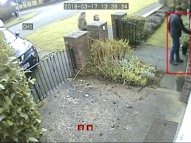
Institute Vision
    To be internationally accredited, Multidisciplinary, and Multi-
    collaborative institute working on technology enabled platform
    fostering innovations and patents through state-of-art academic
    system designed by highly qualified faculty for the development
    of common masses at large
                              Institute Mission
    To educate and train common masses through undergraduate,
    post graduate, research programs by inculcating the values for
    discipline, quality, transparency and foster career and professional
    development for employment thereby contributing to the
    development of society

                         Department Vision
    To be an accredited department of preferred choice among
    common masses in the multidisciplinary field of automation and
    control engineering.
                           Department Mission
          To prepare competent professionals to meet current and
          future demands of industry, academia and society of
          multidisciplinary field of automation.
          To strengthen collaboration with reputed industries and
          institute of global insight.
          To inculcate spirit of research and entrepreneurship amongst
          the students.
                    Program Educational Objectives
       1. Core competency in the multidisciplinary field of automation
          to cater to the industry and research needs.
       2. Multi-disciplinary skills, team spirit and leadership qualities
          with professional ethics, to excel in professional career
          and/or higher studies in Instrumentation and Control
          Engineering.
       3. Prepared to learn and apply contemporary technologies for
          addressing impending challenges for the benefit of
          organization/society.

InstruTech, Vol.3 (2), April-2021
1.PLC based Gate Automation
                                Damini Jadhav

      Abstract – Automated Gate is an automated movable barrier
installed in entrance of any infrastructure for restricted access. At
present, main gate of MVP’s KBT College of Engineering is being
operated manually thus it is hectic for the guards to open and close for
every entry and exit of a vehicle, also it is time consuming. So, it needs

to be automated to reduce human efforts, to save time and avoid traffic.
The project consists of a Rack and Pinion and a Boom Barrier assembly,
whole system is controlled using PLC controller. Both the assemblies i.e.,
rack and pinion and boom barrier are operated using AC motors with
gear box. Also, the lamps at the entrance of the college are controlled

using same PLC.
1. INTRODUCTION

Programmable Logic controller (PLC) is the most powerful tool, which

bought change in the electronics world in automation sector. PLC is well

suited to the cyclic and repetitive operations. Unless a system
reconfiguration is required the functions executed by a PLC are fixed,
the programs need not be changed
Automotive technologies are gaining importance in modern days’ traffic,
safety and security control systems. The manually operated gates of
schools and colleges are hectic to operate, time consuming and may
lead to unforeseen accidents. Hence there is a perpetual need for safety
critical gate control automation to avoid traffic jams, considering human
life safety, and to reduce human efforts.

InstruTech, Vol.3 (2), April-2021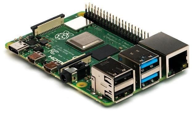
Therefore, in this work we have developed a PLC based Gate Automation
System, in which PLC is going to control two sub gate systems i.e., Rack

and Pinion and Boom Barrier assembly. The system is developed for main

gate of MVP’s KBT College of Engineering. Both the assemblies are

operated using AC motors and gear trains. Besides sensors and limit

switches are used to ensure proper operation of the gate. It is found that

the implemented system works efficiently.
2. PROPOSED SYSTEM

2.1 Block Diagram

                                    Fig -1: Block Diagram

3.1 FLOWCHART

There are two modes of operation:

       i   i. Manual Mode

InstruTech, Vol.3 (2), April-2021
Fig -2: Flow Chart (Manual Mode)

InstruTech, Vol.3 (2), April-2021

Manual Mode:

       • When system is in manual mode all operations will be done
          manually.

In this project we have two basic motors

1. Motor 1 – Main gate motor

2. Motor 2 – Boom barrier motor

• The task to be achieved is that when vehicle comes in front of the
main gate the boom barrier should go up and as the vehicle leaves the
second sensor the barrier should go down.
  To achieve this, we have at present four sensors

  1. Sensor 1 – Main Gate full open position

  2. Sensor 2 – Main Gate full close position

  3. Sensor 3 – Boom Barrier full up position

  4. Sensor 4 – Boom Barrier full down position

  •   When the operator press the main gate open push button (PB).

  •   As soon as the button is pressed the main gate will open and
  remain in the open state till someone press main gate close PB.

  •   The extreme open and close position will be sensed by limit
  switches. When the main gate is open then if the operator press up PB
  the boom barrier will go up and remain up until someone presses
  down PB.

  •   The extreme up and down position will be sensed by the inductive
  proximity sensors.

InstruTech, Vol.3 (2), April-2021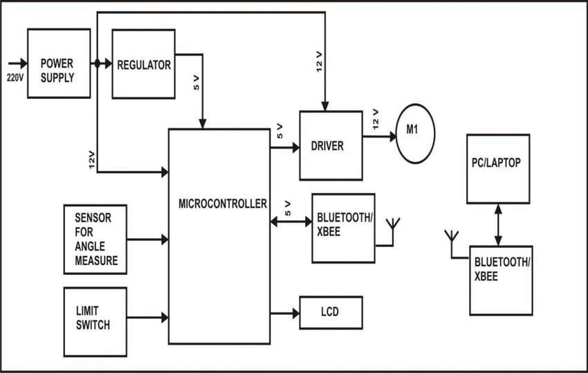
4. SOFTWARE DEVELOPMENT

The software used for programming Siemens PLC’s is Totally Integrated
Automation Portal (TIA Portal) this Innovative simulation tool is highly

flexible, secure, and easy to operate.

It has advanced options like smart selection wizard for error-free
configuration and ordering, Configuration options can be tested and
simulated in advance, we have used student version of TIA V13.

                         Fig -3: TIA Portal Software

5. CONCLUSIONS

Now a days, PLC’s are being used to reduce maintenance and labour
cost of many control systems. Therefore, it is highly recommended that
operations like gate controlling will be based on such advanced
controllers by considering risk factors, we have developed such a control
system. The proposed system is designed to control a Institution gate
with the help of PLC controller, Proximity sensors, Through beam
sensors, Limit switches and Motors. The auto control of this system will

reduce human efforts, labour cost, wastage of time and traffic.

InstruTech, Vol.3 (2), April-2021
Also, the project contributes to a smart campus of a engineering
institution. After on field implementation and successful testing of the
whole system, it was found that the developed system operates very
well.

6. REFERENCES

[1] Kazybek K, Aydarkhan S, Zhantileu S, Dinara J and Md. Hazrat Ali.

(2008) ‘Parking Gate Control Based on Mobile Application.’ 2018 Joint 7th

International Conference on Informatics, Electronics & Vision (ICIEV) and
2018 2nd International Conference on Imaging, Vision & Pattern
Recognition (icIVPR), 399-403.

[2] 'Muhibul H and Md. Ahsanol Kabi. (2010) ‘PLC based Automatic Railway

Gate control system.’ Conference on Electronics and Telecommunication

2010, 136-138.

[3] Ahire D, Attar A, Katare K and Hake C. (2020) ‘Automatic Opening and

Closing of Institute Main Gate.’ International Research Journal of

Engineering and Technology (IRJET), Volume 7, Issue 6, 1239-1243.K.

Elissa, “Title of paper if known,” unpublished.

InstruTech, Vol.3 (2), April-2021

2. Touchless & Automatic Physiotherapy machine for Legs
    Mr. S. R. Pandit, Sarole Gajanan Gangadhar,     Bhandare Satyam
                                    Bhagwan
INTRODUCTION

As the current situation is badly affected by Covid-19 pandemic, many
physiotherapy patients are not getting treatment and physiotherapy
centres are getting closed. In most patients after extensive joint
surgery, attempts at joint motion cause pain and as a result, the patient
fails to move the joint. This allows tissue around the joint to become

stiff and scar tissue is formed. This results in limited range of motion of
the joint and often may take months of physical therapy to recover that
motion. Passive range of motion means, the joint is moved without

use of the patient’s muscles. Due to use of this machine joint receives
nutrition, venous flow increases and deterioration of cartilage is being
prevented. Also pain is decreased, ROM is maintained. Scientific studies
have determined that patients who have troubled achieving the normal
range of motion can be benefited by the use of CPM Machine and the
recovery is accelerated.
Fig.1.1 Manual Physiotherapy

The equipment consists of Geared motors controlled by software, which
receives the data generated by other software, interprets them and
sends the information through drivers to the motors that drive the axles
through synchronized The computerized CPM can be applied to both
upper limbs, enabling computerized control of time and for the ROM to
calculate automatically the speed from the data provided by the

InstruTech, Vol.3 (2), April-2021
physical therapist. The equipment structure includes an adjustable

vertical rod, fixed at the lower end to a support base in a cross shape.
At the upper part of this rod there is an assembly attached, which is
responsible for the elbow flexion/extension movements. This consists of

a metal plate where they are fixed by: Screw Drive arrangement, axles,

angle sensor, Geared Motor. The motor is connected to the screw driver

and platform to Movement Supporter [Ankle]. The arm supporting base
is connected to the support rod and has adjustable angular positioning
that allows for an inclination of up to 90º in the sagittal plane of the
patient's body. This base contains the thief support / and also an

extension adjustment mechanism. The lateral rods from the ankle
supporting base fit the lateral rods of the arm supporting base
This base contains the support for the arm and also has an extension
adjustment mechanism. At the other end of the arm rod, an assembly is

attached    which    is   responsible   for   forearm   pronation/supination

composed by a plate, where the Geared motors and the handle are fixed.
This component is directly connected to the motor axle which can
perform the movement of pronation/supination from 0 to 90º, starting

from the neutral position of the forearm.

InstruTech, Vol.3 (2), April-2021
Fig. 2.1 Block Diagram

REFERENCES:

1. K. Donald Shelbourne and Paul Nitz. Accelerated rehabilitation after

anterior cruciate ligament reconstruction. Am. J. Sports Med. 18, 1990,

pp.292.

2. Nicola Phillips, Michael Benjamin, Tony Everett and Robert W. M. van

Deursen. Outcome and progression measures in rehabilitation following

anterior cruciate ligament injury. Physical Therapy in Sport, 1, 2000,

pp.106-118.

3. O'Driscoll SW, Giori NJ: Continuous passive motion (CPM): Theory and

principles of clinical application.

InstruTech, Vol.3 (2), April-2021
3.Intruder Detection System for Home Security using
                   Open CV on Raspberry Pi 3.
                       Mr. Gupta Nitesh Shyamsundar
ABSTRACT:

Home security system has established its importance and benefits
numerous times by providing immediate monitoring of the house. This is
because of the increasing home theft and burglary incidents that create
an awareness among most of the house owners. CCTV-based security

systems are not real-time because the alert comes to the owner after

the incident occurred unless they are at home during the incident. To

overcome this problem, many researchers are developing cost-effective

custom-based security systems, which are affordable for everyone. Most
of these systems use a Passive Infrared (PIR) motion sensor for

motion detection. Although affordable, such a system still has many

limitations. For example, false alarms triggered due to an abnormal

condition such as rapid heating from sunlight exposure. In this work, a

vision-based home security system using OpenCV on Raspberry Pi 3

model B was developed to improve the effectiveness of motion detection.

This   system    applied    the     Hear-Cascade   algorithm   coupled   with
background subtraction as well as considered the Histogram of
Oriented Gradients (HOG) during the development stage. The

developed prototype was tested under a few conditions to determine the
accuracy of motion detection and compare the results with a system that
uses a PIR motion sensor for motion detection. From the results
obtained, the developed vision based home security system using

InstruTech, Vol.3 (2), April-2021
OpenCV has 100% of detection rate compared to the PIR motion sensor- based security system with 76% of the detection rate. INTRODUCTION Nowadays, the evolution of technology-based systems has drastically increased over the past few years. As the technology grows, it is no surprise that most of the work that was done by human will be taken over by machines. Although many people believe that this will make everyone to be lazy, it is an undeniable fact that this is for the betterment of humankind. Consequently, they have to confront this technology every day, which undoubtedly affects their lifestyle from the way they live until the way they work or relax. The convenience that technology provides them is the most common reason for their willingness to get it to affect their daily lifestyle to such extent Security has always been a major issue everywhere around the globe and the importance of security cannot be denied in today’s society because of the increasing crime rate. For instance, in Malaysia, the high crime rate can make it a less safe place to stay. Home theft rate in Malaysia is the second highest crime [1] and this creates awareness in the society. Home security systems development using IoT infrastructure has become ubiquitous because of the high home theft rate. The most common features of the home security system are motion detection, live monitoring, and alert notification. Systems relying only on a Passive Infrared (PIR) sensor to accommodate for motion detection have unreliable detection rate because it could trigger a false alarm due to abnormal conditions such as pet intrusion or rapid heating [2] e.g., from InstruTech, Vol.3 (2), April-2021
sunlight exposure. False alarms can have significant impacts such as in

security systems that trigger calls to the police [3] or other emergency

agencies.

SOFTWARE & HARDWARE IMPLEMENTATION

1. OpenCV

OpenCV (Open-Source Computer Vision Library) is an open-source

computer vision and machine learning software library. OpenCV was built
to provide a common infrastructure for computer vision applications and
to accelerate the use of machine perception in the commercial products.

Being a BSD-licensed product, OpenCV makes it easy for businesses to

utilize and modify the code.

     2. Passive Infrared (PIR) Sensor

PIR is a type of motion sensor. Fresnel lens, comparator, amplifier
circuitry and time delayer circuitry are combined to form the basic
Passive Infrared Device (PID) structure. The Fresnel lens in the PIR
motion sensor has a special filter that allows the infrared signal to be
focused onto the component. The Fresnel lens in a PIR motion sensor

captures the incoming infrared (IR) radiation and direct its focus to the

InstruTech, Vol.3 (2), April-2021
centre point. The IR source moves and exposes one element at a time. The Fresnel lens detection range can go up to 30m and thus suitable for applications like PIR sensors. PIR sensor is one of the important mechanisms for motion detection in a security system. The sensor’s functionality is to detect heat emitted from a human or a living body. The change in the radiation of infrared signal produced by moving warm- blooded living things is how the sensor detects. It is indeed the foundation tool for motion detection but using only PIR motion sensor to evaluate a movement will be insufficient. 3. Raspberry Pi The Raspberry Pi is a low cost, credit-card sized computer that plugs into a computer monitor or TV, and uses a standard keyboard and mouse. It is a capable little device that enables people of all ages to explore computing, and to learn how to program in languages like Scratch and Python. It’s capable of doing everything you’d expect a desktop computer to do, from browsing the internet and playing high- definition video, to making spreadsheets, word-processing, and playing games. InstruTech, Vol.3 (2), April-2021
SYSTEM IMPLEMENTATION

      System Flowchart

InstruTech, Vol.3 (2), April-2021
Video Streaming Demonstration CONCLUSION: In this work, a home security system using a camera with OpenCV implementation has been successfully developed on Raspberry Pi 3 Model B. The system composed of both hardware and software implementations, where both parts collaborate to form an effective motion detection mechanism. The Haar-Cascade algorithm coupled with a background subtraction method was applied in the OpenCV implementation. The results obtained from the three conducted experiments suggest the high-accuracy of a vision-based motion detection system, eliminating false 020013-9 alarms. This OpenCV motion detection system was shown to be more effective than the developed PIR motion detection system, with a passing rate average of 100% against 76% based on the three experiments conducted InstruTech, Vol.3 (2), April-2021
REFERENCE:

[1] M. Menon, "Innovating to zero crime rate," in Digital News Asia, ed,

  (2015).

[2] M. Pugh, J. Brewer, and J. Kvam, "Sensor fusion for intrusion detection

  under false alarm constraints," in 2015 IEEE Sensors Applications

  Symposium (SAS), (2015), 1-6.

[3] R. Sampson, "False burglar alarms," in Problem-Oriented Guides for

  Police: Problem-Specific Guides Series No. 5, U. S. D. o. J. Office of

  Community Oriented Policing Services, Ed., 2 ed, (2007).

[4] P. Vigneswari, V. Indhu, R. Narmatha, A. Sathinisha, and J. Subashini,

  "Automated security system using surveillance," International journal

  of current engineering and technology, vol. 5, no. 2, 882-884, (2015).

4.Bio-Medical Signal Interface with DICOM Standard

  Ms. Tejasvini Kailash Jadhav, Mr. Harshad Nandkishor Shirude,

                       Mr. Sahil Vivek Gaikwad

ABSTRACT :

In this project we proposed to inteface biomedical signal (

ECG,EEG,EMG)with DICOM standard using IOT.DICOM stands for

the Digital Imaging & Communication in medicine .DICOM defines
the formats for medical images that can be exchanged with the
data & quality necessary for clinical use. DICOM is implemented in

InstruTech, Vol.3 (2), April-2021
almost every radiology, cardiology imaging & radiotherapy device (X-ray,CT scan,MRI,Ultrasound etc) The DICOM Network Protocol architecture: Looks something like this Network ⇒ TCP/IP ⇒ DICOM ULP for TCP/IP ⇒ UL Service boundary ⇒ DICOM Message Exchange ⇒ Medical Imaging Application. To interface biomedical signals with DICOM we need software and hardware parts. In hardware side we need AD8232 sensor which used as signal conditioner in ECG signal, microcontroller 8051 to control all the activities and wifi module for connectivity. In software side we need any website which will work as server, mobile application to monitor the ECG signal . AD8232: The AD8232 is an integrated signal conditioning block for ECG and other biopotential quantification applications. The supply current is typically 170µA and the operating voltage and temperature range is 2.0 to 3.6 V and −40°C to +85°C respectively. This withal contains the 2-pole adjustable high pass filter and it can accept up to ±300 mV of half cell potential. It has a high signal gain of 100. It may contain two electrode configuration or three electrode configurations and the sensor contains five pins namely L0-, L0+, Output Vcc, GND, and SND. InstruTech, Vol.3 (2), April-2021
NODE MCU:

This board contains a microcontroller and WiFi module. The operating

voltage of ESP 8266 is 3.3 V. The single board microcontroller utilized in

this board contains 12 GPIO pins and D0.
WORKING:

The three lead ECG pins are connected to AD8232 sensor through which
it senses by placing its sensing tips on three different places of patient
body, at right arm, left arm and right leg AD8232 amplifies the signal
engendered at the sensing tips of the pins and convert this physical
quantity which is in analog nature into electrical quantity in terms of
volts.These engendered signals in terms of voltage are supplied to Node
MCU which accumulates the data from the sensor by processing and
send this data to the cloud. A cloud IoT predicated platform application

is utilized to post and visualize data on the cloud.Here we used such type
of platform called ThingSpeak to post and visualize the data on cloud
which updates perpetually predicated on the data given by the Node
MCU.The Node MCU provides the authenticate ID through which the
target end users can authenticate for access and can avail the
accommodations.
ADVANTAGES:

It can store the patient data every day.

It is more secure.

Less power consumption.

The visualization of the patient heart rate is good.

InstruTech, Vol.3 (2), April-2021
Less cost.
CONCLUSION:

The enhanced features of the smartphone, such as ro-bust sensors,

wireless communication technologies high-speed processors, and a
growing number of usage,made use of smartphones very vital in cardiac
health monitoring. A categorical review of smartphone-based systems for

real-time cardiac monitoring and abnormal-ity detection is presente in

this paper. The primaryfocal point was the analysis of ECG for heart

abnormal-ity detection using wearable sensors and smartphones.
Reference:

https://www.dicomstandard.org/about

https://www.extrahop.com/company/blog/2016/introduction-to-dicom-

protocol/

InternationalJournal of engineering and advance technology ( remote

ecg monitoring system using IOT)

Survey: Smartphones – based assessment of cardiovascular diseases
using ECG and PPGanalysis
Muhammad Shabaan1, kaleem Arshid2, Muhammad Yaqub2+, Feng

Jinchao2,3*+, M. Sultan Zia4, Giridhar Reddy Bojja5, Muazzam Iftikhan6,
Usman Ghani6, Loknath Sai Ambati5 and Rizwan Munir7

InstruTech, Vol.3 (2), April-2021
5. Calibration
                        Ms. Meenal Ramchandra Waje

INTRODUCTION

In measurement technology           and metrology, calibration is      the
comparison     of measurement values     delivered   by   a device   under
test with those of a calibration standard of known accuracy. Such a
standard could be another measurement device of known accuracy, a
device generating the quantity to be measured such as a voltage,
a sound tone, or a physical artifact, such as a meter ruler.

The outcome of the comparison can result in one of the following:

   no significant error being noted on the device under test
   a significant error being noted but no adjustment made
   an adjustment made to correct the error to an acceptable level

Strictly speaking, the term "calibration" means just the act of comparison

and does not include any subsequent adjustment.

The calibration standard is normally traceable to a national or
international standard held by a metrology body.

BIPM Definition

The increasing need for known accuracy and uncertainty and the need
to have consistent and comparable standards internationally have led to
the establishment of national laboratories. In many countries a National

Metrology Institute (NMI) will exist which will maintain primary standards

of measurement (the main SI units plus a number of derived units) which

InstruTech, Vol.3 (2), April-2021
will be used to provide traceability to customer's instruments by calibration. The NMI supports the metrological infrastructure in that country (and often others) by establishing an unbroken chain, from the top level of standards to an instrument used for measurement. Examples of National Metrology Institutes are NPL in the UK, NIST in the United States, PTB in Germany and many others. Since the Mutual Recognition Agreement was signed it is now straightforward to take traceability from any participating NMI and it is no longer necessary for a company to obtain traceability for measurements from the NMI of the country in which it is situated, such as the National Physical Laboratory in the UK. Quality To improve the quality of the calibration and have the results accepted by outside organizations it is desirable for the calibration and subsequent measurements to be "traceable" to the internationally defined measurement units. Establishing traceability is accomplished by a formal comparison to a standard which is directly or indirectly related to national standards (such as NIST in the USA), international standards, or certified reference materials. This may be done by national standards laboratories operated by the government or by private firms offering metrology services. Quality management systems call for an effective metrology system which includes formal, periodic, and documented calibration of all measuring instruments. ISO 9000 and ISO 17025 standards require that these traceable actions are to a high level and set out how they can be quantified. InstruTech, Vol.3 (2), April-2021
To communicate the quality of a calibration the calibration value is often
accompanied by a traceable uncertainty statement to a stated
confidence level. This is evaluated through careful uncertainty analysis.

Sometimes a DFS (Departure From Spec) is required to operate

machinery in a degraded state. Whenever this does happen, it must be
in writing and authorized by a manager with the technical assistance of
a calibration technician.

Measuring devices and instruments are categorized according to the
physical    quantities   they    are   designed     to     measure. These        vary

internationally, e.g., NIST 150-2G in the U.S. and NABL-141 in India.
Together, these standards cover instruments that measure various
physical       quantities       such     as electromagnetic             radiation (RF

probes), sound (sound       level   meter or noise        dosimeter),     time   and

frequency (intervalometer), ionizing radiation (Geiger counter), light

(light     meter),   mechanical        quantities        (limit   switch, pressure

gauge, pressure switch), and, thermodynamic or thermal properties

(thermometer, temperature controller). The standard instrument for each

test device varies accordingly, e.g., a dead weight tester for pressure
gauge calibration and a dry block temperature tester for temperature
gauge calibration.

Instrument calibration prompts

Calibration may be required for the following reasons:

   a new instrument
   after an instrument has been repaired or modified

InstruTech, Vol.3 (2), April-2021
moving from one location to another location
     when a specified time period has elapsed

     when a specified usage (operating hours) has elapsed

     before and/or after a critical measurement

     after an event, for example
     o    after an instrument has been exposed to a shock, vibration, or
          physical damage, which might potentially have compromised the
          integrity of its calibration
     o    sudden changes in weather
     whenever       observations      appear    questionable    or     instrument
     indications do not match the output of surrogate instruments

     as    specified   by   a   requirement,     e.g.,   customer    specification,

     instrument manufacturer recommendation.

In general use, calibration is often regarded as including the process
of adjusting the output or indication on a measurement instrument to
agree with value of the applied standard, within a specified accuracy. For
example, a thermometer could be calibrated so the error of indication
or        the    correction      is      determined,     and    adjusted       (e.g.

via calibration constants) so that it shows the true temperature

in Celsius at specific points on the scale. This is the perception of the

instrument's end-user. However, very few instruments can be adjusted

to exactly match the standards they are compared to. For the vast
majority of calibrations, the calibration process is actually the
comparison of an unknown to a known and recording the results.

InstruTech, Vol.3 (2), April-2021
Basic calibration process Purpose and scope The calibration process begins with the design of the measuring instrument that needs to be calibrated. The design has to be able to "hold a calibration" through its calibration interval. In other words, the design has to be capable of measurements that are "within engineering tolerance" when used within the stated environmental conditions over some reasonable period of time. Having a design with these characteristics increases the likelihood of the actual measuring instruments performing as expected. Basically, the purpose of calibration is for maintaining the quality of measurement as well as to ensure the proper working of particular instrument. Frequency The exact mechanism for assigning tolerance values varies by country and as per the industry type. The measuring of equipment is manufacturer generally assigns the measurement tolerance, suggests a calibration interval (CI) and specifies the environmental range of use and storage. The using organization generally assigns the actual calibration interval, which is dependent on this specific measuring equipment's likely usage level. The assignment of calibration intervals can be a formal process based on the results of previous calibrations. The standards themselves are not clear on recommended CI values: ISO 17025 "A calibration certificate (or calibration label) shall not contain any recommendation on the calibration interval except where this has been InstruTech, Vol.3 (2), April-2021
agreed with the customer. This requirement may be superseded by legal

regulations.”

ANSI/NCSL Z540

"...shall be calibrated or verified at periodic intervals established and

maintained to assure acceptable reliability..."

ISO-9001

"Where necessary to ensure valid results, measuring equipment shall...be

calibrated or verified at specified intervals, or prior to use...”

MIL-STD-45662A

"... shall be calibrated at periodic intervals established and maintained to

assure acceptable accuracy and reliability...Intervals shall be shortened
or may be lengthened, by the contractor, when the results of previous
calibrations indicate that such action is appropriate to maintain
acceptable reliability."

  Standards required and accuracy

The next step is defining the calibration process. The selection of a

standard or standards is the most visible part of the calibration process.

Ideally, the standard has less than 1/4 of the measurement uncertainty

of the device being calibrated. When this goal is met, the accumulated
measurement uncertainty of all of the standards involved is considered
to be insignificant when the final measurement is also made with the 4:1

ratio. This ratio was probably first formalized in Handbook 52 that

accompanied MIL-STD-45662A, an early US Department of Defense

metrology program specification. It was 10:1 from its inception in the

InstruTech, Vol.3 (2), April-2021
1950s until the 1970s, when advancing technology made 10:1

impossible for most electronic measurements.

Maintaining a 4:1 accuracy ratio with modern equipment is difficult. The
test equipment being calibrated can be just as accurate as the working
standard. If the accuracy ratio is less than 4:1, then the calibration

tolerance can be reduced to compensate. When 1:1 is reached, only an
exact match between the standard and the device being calibrated is a
completely correct calibration. Another common method for dealing with
this capability mismatch is to reduce the accuracy of the device being
calibrated.

For example, a gauge with 3% manufacturer-stated accuracy can be

changed to 4% so that a 1% accuracy standard can be used at 4:1. If the

gauge is used in an application requiring 16% accuracy, having the gauge

accuracy reduced to 4% will not affect the accuracy of the final

measurements. This is called a limited calibration. But if the final

measurement requires 10% accuracy, then the 3% gauge never can be

better than 3.3:1. Then perhaps adjusting the calibration tolerance for

the gauge would be a better solution. If the calibration is performed at

100 units, the 1% standard would actually be anywhere between 99 and

101 units. The acceptable values of calibrations where the test

equipment is at the 4:1 ratio would be 96 to 104 units, inclusive.
Changing the acceptable range to 97 to 103 units would remove the
potential contribution of all of the standards and preserve a 3.3:1 ratio.
Continuing, a further change to the acceptable range to 98 to 102
restores more than a 4:1 final ratio.

InstruTech, Vol.3 (2), April-2021
This is a simplified example. The mathematics of the example can be

challenged. It is important that whatever thinking guided this process in

an actual calibration be recorded and accessible. Informality contributes
to tolerance stacks and other difficult to diagnose post calibration
problems.

Also in the example above, ideally the calibration value of 100 units
would be the best point in the gauge's range to perform a single-point

calibration. It may be the manufacturer's recommendation or it may be

the way similar devices are already being calibrated. Multiple point

calibrations are also used. Depending on the device, a zero unit state,
the absence of the phenomenon being measured, may also be a
calibration point. Or zero may be resettable by the user-there are several

variations possible. Again, the points to use during calibration should be

recorded.

There may be specific connection techniques between the standard and
the device being calibrated that may influence the calibration. For
example, in electronic calibrations involving analog phenomena, the
impedance of the cable connections can directly influence the result.

  Manual and automatic calibrations

As an example, a manual process may be used for calibration of a
pressure gauge. The procedure requires multiple steps, to connect the
gauge under test to a reference master gauge and an adjustable
pressure source, to apply fluid pressure to both reference and test
gauges at definite points over the span of the gauge, and to compare
the readings of the two. The gauge under test may be adjusted to ensure
its zero point and response to pressure complies as closely as possible

InstruTech, Vol.3 (2), April-2021
to the intended accuracy. Each step of the process requires manual

record keeping.

An automatic pressure calibrator is a device that combines an electronic
control unit, a pressure intensifier used to compress a gas such
as Nitrogen, a pressure transducer used to detect desired levels in
a hydraulic accumulator, and accessories such as liquid traps and
gauge fittings. An automatic system may also include data collection

facilities to automate the gathering of data for record keeping.

  Process description and documentation

All of the information above is collected in a calibration procedure, which
is a specific test method. These procedures capture all of the steps

needed to perform a successful calibration. The manufacturer may
provide one or the organization may prepare one that also captures all
of the organization's other requirements. There are clearinghouses for

calibration procedures such as the Government-Industry Data Exchange

Program (GIDEP) in the United States.

This exact process is repeated for each of the standards used until
transfer standards, certified reference materials and/or natural physical
constants, the measurement standards with the least uncertainty in the
laboratory,    are   reached. This   establishes   the traceability of   the

calibration.

See Metrology for other factors that are considered during calibration
process development.

After all of this, individual instruments of the specific type discussed
above can finally be calibrated. The process generally begins with a basic

InstruTech, Vol.3 (2), April-2021
damage check. Some organizations such as nuclear power plants collect

"as-found" calibration data before any routine maintenance is performed.
After routine maintenance and deficiencies detected during calibration
are addressed, an "as-left" calibration is performed.

More commonly, a calibration technician is entrusted with the entire
process and signs the calibration certificate, which documents the
completion of a successful calibration. The basic process outlined above

is a difficult and expensive challenge. The cost for ordinary equipment

support is generally about 10% of the original purchase price on a yearly

basis, as a commonly accepted rule-of-thumb. Exotic devices such
as scanning      electron     microscopes, gas   chromatograph systems
and laser interferometer devices can be even more costly to maintain.

The 'single measurement' device used in the basic calibration process
description above does exist. But, depending on the organization, the
majority of the devices that need calibration can have several ranges
and much functionality in a single instrument. A good example is a

common      modern oscilloscope.    There   easily   could   be   200,000
combinations of settings to completely calibrate and limitations on how
much of an all-inclusive calibration can be automated.

InstruTech, Vol.3 (2), April-2021
An instrument rack with tamper-indicating seals

To prevent unauthorized access to an instrument tamper-proof seals are

usually applied after calibration. The picture of the oscilloscope rack
shows these, and proves that the instrument has not been removed
since it was last calibrated as they will possible unauthorized to the
adjusting elements of the instrument. There also are labels showing the
date of the last calibration and when the calibration interval dictates
when the next one is needed. Some organizations also assign unique
identification to each instrument to standardize the record keeping and
keep track of accessories that are integral to a specific calibration
condition.

When the instruments being calibrated are integrated with computers,
the integrated computer programs and any calibration corrections are
also under control.

Calibration and verification of instruments
A fundamental aspect of science is measurement and a key challenge to
scientists is to minimize associated errors in cost-effective ways (Hand,

2004). As instruments increase in sensitivity and hence cost, this balance

becomes harder to achieve. Neverthe less, it is a balance that must be

made. A key part of measurement is the process of calibration. This involves
checking the reading of an instrument against known values that span an
anticpated range or comparing an instrument’s readings with those of a
gold-standard equivalent and should not be confused with graduation; this
is simply the marks on an instrument’s dial that allow a measurement to
be recorded. Calibration should occur immediately before an instrument

issued. Comparators should have a direct link with the National Physical

InstruTech, Vol.3 (2), April-2021
Laboratory (http:// www.npl.co.uk/) or the System International dugite’s

(http://www.bipm.org/en/home/). There aren’t many of us who have wrestled

with chemical-based Lloyd-Haldane or micro-Schlender apparatus to
determine the concentrations of oxygen and carbon dioxide in expired air
or use these contraptions to confirm the concentrations of gases used to
calibrate electronic instruments. Those who haven’t should consider

themselves fortunate. In 1898, John Haldane introduced his system

(Haldane, 1898) and in 1958, Brian Lloyd refined the device (Lloyd, 1958)

which then became known as LloydHaldane apparatus. Incidentally, in 1970

Lloyd became Rector of the then Oxford Polytechnic (now Oxford Brookes

University) and is credited with introducing the modular system that

Chiractries   academic     courses   in   most   UK-based    highereducation

institutions. Lloyd was also a capable sport and exercise physiologist.

Schlender’s (1948) device required as little as 0.5 ml of air whereas

LloydHaldane apparatus required some 15–20 ml. The development of

widely-available electronic analyzers in the 1960s and 1970s was a key

advance. However, instruments were prone to drift. This was a problem for

the increasingly used long-duration exercise trials in which participants
exercised for hours as part of studies of their metabolism and other related
aspects. Exercise was and is, frequently to volitional exhaustion. As a result,

half-hour or so intra-trial verifications of instruments were required and

usually, re-setting was necessary. Continued improvements both in the

stability and sensitivity of instrumentation — especially for breath-by-

breath on-line devices — have reduced problems of drift but these problems

have not been eliminated. The process of verification tends to be

overlooked. While authors commendably, report calibration procedures, it

is rare to see equivalent intra- or aftertrial verifications described. Just as

InstruTech, Vol.3 (2), April-2021
calibration should occur immediately before an instrument is used,
verification should be undertaken immediately after an instrument’s use.
Moreover, depending on the length of a trial, verification should also occur
during the trial. However, while all this is a hallmark of good practice, it is

not inviolate. For instance, a master-builder friend of mine was tiling an area

immediately adjacent to a swimming pool. While he was working, another
builder immediately next to him proceeded to do some drilling with a drill
plugged into the mains electricity supply. My friend challenged his colleague

by pointing out that water and electricity were not the best of companions.

The colleague retorted that there was an earth-leakage circuit breaker that
would trip if anything untoward occurred and it had been checked before
drilling began. ‘‘Hmmm’’ replied my non-pulsed pal, ‘‘You still don’t know if

the breaker will work when it is really needed. Go away and come back

when I’m finished’’ (or words to that effect). This is a nice if extreme

example that pre-test calibration and testing are not sacrosanct. Verification

of instruments and devices must also occur. If drift is detected, one then

has to consider how readings should be adjusted. Similarly, it is not easy to

calibrate devices such as force platforms and online-gas analyzers because

they respond mainly to ever-changing, often stochastic events. This though

is a matter for another time. So, authors who submit manuscripts to the
Journal of Sports Sciences are urged to report not only how they calibrated
instruments before testing but also how they verified instruments
immediately after such testing and, as appropriate, during long-duration

trials.

InstruTech, Vol.3 (2), April-2021
REFERENCES
      Haldane, J. (1898). Some improved methods of gas analysis. Journal

      of Physiology, 22, 465–480. Hand, D. J. (2004). Measurement theory

      and practice. London: Arnold

      Lloyd, B. B. (1958). Development of Haldane’s gas analysis

      apparatus. Journal of Physiology, 143, 5–6P. Schlender, P. F. (1948).

      Analyzer for accurate estimation of respiratory gases in one-half

      cubic centimeter samples. Journal of Biological Chemistry, 167,
      235–250
      https://en.wikipedia.org/wiki/Calibration

          6.LED On Off (Based On Google Assistant)

                                Prasad B. Bondarde
   ABSTRACT: -

                   LED on/off Based on Google Assistant which can also
be used for home automation, to automate our home LED lights by using
Google assistant/Alexa & we can also use in automation of Fan, AC,

Heater, etc. This project gives us freedom to automate our homes from

anywhere. The only things we need is phone and the internet.

   1. Hardware: -

            LED (Light Emitting Diode)
            ESP32 development boards module
            Resistor
            Jumper wire male female
            USB cable

InstruTech, Vol.3 (2), April-2021
2. Software part: -
Account on IFTTT
Account on Adafruit IO
Coding Part
Step 1 :- Setup for Adafruit IO for IOT control Device
Adafruit IO is an IOT platform build around the MQTT (Message
Queuing Telemetry Transport) in the Adafruit IO we have created
the feed for LED control Create 1 block for LED on off switch.
Step2 :- Connection to Google Assistant through IFTTT
In this step, by using new Applet we will connect our Google
Assistant to
the Adafruit IO MQTT Broker to allow us to control the lights
with voice
commands. To do this we are using IFTTT (If This Then That)
platform.
InstruTech, Vol.3 (2), April-2021If we add in If This we say “Turn on LED” then That send data to
Adafruit
IO.
Step3 :-Coding Part
In coding part we have defined my Adafruit AIO key, User Name,
Server and
Server Port (1883)
Working:-
In this project we have used Google Assistant with Adafruit IO to Control
an LED with ESP32. So here we are using IFTTT to access Google
InstruTech, Vol.3 (2), April-2021Assistant and control LED by using voice commands. ESP32 has been
programmed by using Arduino IDE, limiting resistor is used in the circuit
to limit the current, hence preventing the LED from getting damaged.
For turning the LED on a person should say “OK Google Turn on LED”
and this command will be sent to IFTTT cloud server then it will revert
it to Google Assistant and it will reply with “OK! Turning on LED” and at
that time IFTTT will send this command to Adafruit IO and in Adafruit
IO there is LED control feed in Adafruit IO and it will turn on the button
and Adafruit IO will send this feed to ESP 32 by using MQTT(Message
Queuing Telemetry Transport). We have connected Negative pin on
ESP32 GND pin and Positive pin of LED is connect to D2 pin of ESP32.
For turning the LED off “OK Google Turn off LED” command is given the
same process is repeated and the LED is turned off.
References :-
1. IFTTT:- https://ifttt.com/discover
2. ESP32:-https://randomnerdtutorials.com/esp32-pinout-reference-
gpios/
3. Arduino IDE:- https://www.arduino.cc/en/Guide/Environment
7. Danger with food
Abhijit Ravindra Kulkarni
We come across diversified food in our life. The food contains
various preservatives, additives, colors, and other chemicals that we are
required to know now a day. Fruits and vegetables are extensively used
InstruTech, Vol.3 (2), April-2021in daily intake of many Indian families. To make the vegetables safe from
insects, pesticides are used on vegetables in different stages. In a near
history it was identified that a ship full of grapes those were exported to
other countries were rejected by specific countries. These countries did
not allow to throw the grapes those had higher amount of pesticides
than expected in their sea. This enforces use of instruments to detect
the pesticide content in fruits and vegetables. Commonly used
instruments include ultra-high-performance liquid chromatography/time-
of-flight mass spectrometry (UHPLC/TOF–MS), analytical weighing
balance, homogenizer, rotary evaporator, centrifuge, evaporator,
vacuum manifold [1]. In [1] mention of 60 pesticides analysis in
vegetables and fruits samples is there. Accuracy better than 2 ppm is
expressed as well. Statistical parameter like relative standard deviation,
uncertainty and repeatability, calibration curves are also explored.
Some pesticides detected in vegetables includes Chlorpyriphos
(Cauliflower), Monocrotophos (Cabbage), Endosulfan-T (Fish), Fenitrothion
and Phorate (wheat), Aldrin (Rice and Milk,Banana,Apple,), Chlordane
(Banana), Heptachlor and Endosulfan-T (Butter), Cyfluthrin-Beta (tomato)
[2]. Monocrotophos, Endosulfan-T, Lindane, Cypermethrin,
Phorate & Dimethoate were generality identified in Maharashtra [2].
Though the reference [2] is old, it emphasises importance of study area.
Some food additives are on [3]. It discusses Hyperactivity, Asthma
– and Cancer those are probably caused by number of food additives.
This includes red, yellow, blue and other food colours. There are number
of preservatives that can cause asthma and cancer. Further synthetic
antioxidants, food stabilizer, thickening and stabilizing agents, laxative,
InstruTech, Vol.3 (2), April-2021& emulsifier, anticaking agent, Gelling stabilizers, Hydrolyzing enhancer,
softner, flavor enhancers, Anti foaming, Lubricant agents, Coating,
glazing, agents used in Bleaching Flour, Sweetner.
So be careful while purchasing food from outside!
REFERENCES:
[1] P. Sivared, perumal, P. Anand, L. Riddhi,Rapid determination of
pesticide residues in fruits and , vegetables, using ultra-high-
performance liquid chromatography/time-of-flight mass spectrometry,
Food Chemistry 168 (2015) 356–365.
[2] Summary of Monitoring of pesticide residues at National
Level25november 2010.
[3] www.traditionaloven.com/articles/122/dangerous-food-additives-to-
avoid
8. Key challenges in wind power in India
Dr. A. K. Patil
INTRODUCTION:
The demand of energy is increasing day by day with emerging
technologies. Availability of energy can help the sustainable economic
development. Due to the population scenario, almost 1.4 billion people
in India, the challenge is bigger for India to create a better life. Energy
demand is increasing in all the sectors viz agriculture, process and all
types of industries, commercial and residential areas and also it will
continue to grow. In spite of creation of environmental pollution, most
InstruTech, Vol.3 (2), April-2021of the world’s commercial energy if fulfilled by fossil fuels. To overcome
the issues like global warming and other problems of power generation
using fossil fuels, Renewable energy technology is enhanced. The Net
Zero Challenge of world economic forum, mansion that the Global
greenhouse gas emissions increases by 1.5% per year. If it will reduce by
5% per annum, then the global warming to will limit to 1.5°C [1]. India
should implement new and efficient technologies to achieve a net-zero
emissions challenge. [2]. The sustainable natural resources producing
renewable energy can contribute for sustainable development. Wind
energy is one of the cheapest and cleanest renewable energy sources
which can significantly contribute to the installed grid power capacity in
India. That is the reason that the wind energy is renewable and
environment friendly, systems that convert wind energy to electricity
have developed rapidly. The contribution of wind energy is the largest in
renewables growth (1.4 EJ) in 2019. In 2019, wind supplied 1430 Tw of
electricity, which was 5.3% of worldwide electrical generation, [3] with the
global installed wind power capacity reaching more than 651 GW, an
increase of 10% over 2018 [4]. Wind Energy contributes the major portion
of 36.99% of total renewable energy capacity of the India [5].
Key challenges in the development of wind energy in India
The biggest barrier in yoking the wind energy is transmission.
Because of lack of grid evacuation capacity and appropriate
infrastructure for transmission, the potential wind sites
InstruTech, Vol.3 (2), April-2021in Rajasthan, Gujarat, and coastal Tamil Nadu remain have less
tapped.
Use of new technology is lacking in India due to various issues,
and so poor design causes number of failures. The maintenance is
very costly. It makes the wind energy less reliable.
The negligence in design consideration for earthling and lightning
protection lead to control system breakdown by lightning strike. It
hampers the reliability [6].
Due to grid problems, at start of wind turbines tremendous voltage
fluctuations are there. It reduces the power quality and affect the
customer’s appliances. The fluctuations cause weakening of grid
reducing reliability [6].
The sites where wind has good scenario, it is big challenge to
convert that land from agricultural to non-agricultural and get
permission for wind power plant from authorities, or it very much
time-consuming and difficult.
Identifying the suppliers for getting good quality raw material in
time is again a challenge in supply chain issues.
Still it is possible to compete the wind power with conventional
thermal power economically but the available locations mare not
always windy enough.
Offshore wind turbines which are remotely located can generate
good energy, but again the issue is with the infrastructure of
transmission lines which must be able to brought the electricity
from the wind farm to the city.
The usefulness of wind farms must compete with the alternative
use of land.
InstruTech, Vol.3 (2), April-2021Though the wind turbines have little impact on environment, it
causes noise and aesthetic pollution. .
Wind turbine harm wild life as birds get killed by rotating turbine
blades. Research is going on the saving wild life to reduce the
impact of wind turbines on these species [7].
REFERENCES:
[1] The world Economic Forum, The Net-Zero Challenge: Global Climate
Action at a Crossroads (Part 1),
(https://www.weforum.org/reports/the-net-zero-challenge-global-
climate-action-at-a-crossroads-part-1)
[2] India: Transforming to a net-zero emissions energy system,
(https://www.teriin.org/sites/default/files/2021-
03/India_Transforming_to_a_net-ero_emissions_energy_system.pdf)
[3] Statistical Review of World Energy 2020 | 69th edition,
(https://www.teriin.org/sites/default/files/2021-
03/India_Transforming_to_a_net-ero_emissions_energy_system.pdf)
[4] Global Wind Report 2019 | Global Wind Energy Council,
(https://gwec.net › global-wind-report-2019)
[5] Garcia-Garcia, G., Woolley, E., Rahimifard, S. et al. (2017). A
Methodology for Sustainable Management of Food Waste. Waste
Biomass Valor 8, 2209–2227. https://doi.org/10.1007/s12649-016-
9720-0
InstruTech, Vol.3 (2), April-2021[6] Victor K. Mallet “The Use of Wind Energy in India - Lessons learned”,
Term Paper, Sustainable Energy, 10.391J Spring 2001
[7] IEA India 2020 - Indepth Energy Policy Review,
(http://www.niti.gov.in/node/1015)
9. Fruits and Vegetables Sanitizer
Ms. Rao Aishwarya, Ms. Thapa Urmila
INTRODUCTION:
Washing of fruits and vegetables is vital step in any processing
operation, which gives attractive and chemical free fruit. Washers may
be continuous type or batch type. The batch type washer is
recommended only for small plants or community installations. Presently
the fruits are being washed by one or the combination of various
washing methods by manually or mechanically. Washing is an important
primary process unit operation, which reduces the surface microbial
load, while removing the field soil, dust and even residual pesticides,
thus leading to the value addition of the produce at the farm level.
Contamination of fruits and vegetables is generally due to unsanitary
cultivation and marketing practices [1]. The estimation of level of
microbial contamination of food allows the assessing of shelf life of food,
which is important from the health and economic point of view [2]. The
microorganisms involved with the food if pathogenic, can be critical from
a public health point of view, because they can lead to health hazard [3].
InstruTech, Vol.3 (2), April-2021Fruit washing is a mandatory processing step; it would be wise to eliminate spoiled fruit before washing in order to avoid the pollution of washing tools and / or equipment and the contamination of fruit during washing. Fruit washing can be carried out by emersion, by spray/showers or by combination of these two processes which is generally the best solution. Relatively very little information is available in research literature on small- scale fruit washer. Proposed System in the Project: The inputs are start, stop and emergency stop. LCD display is to be used for indicating which process is going on in the device. The power supply to be used is 0-12 VDC. The sprinkler will perform washing operation. The SMPS is to be used as blower which will perform drying process and UV- C lamp is to be used for sanitization. We are going to control all this function using pic 16f877a microcontroller. This device is designed for three processes i.e. washing, drying and UV sanitization. Each process requires different time setting. When Start button is pressed, the device will provide the facility to select the modes wash, dry and UV-C sanitization. The sequence is 1) wash 2) Dry 3) Sanitize but we can select the random mode. After selection of mode we have to select the time according to the requirement. There are count down timers used which will count the time in descending order and stops when time become 0 and the process will end. InstruTech, Vol.3 (2), April-2021
You can also read