JC REFRIGERATION INSTALLATION MANUAL - Jr and Jeremy Lambright www.jc-refrigeration.com
←
→
Page content transcription
If your browser does not render page correctly, please read the page content below
Norcold 1200 1201 1210 1211
           Hvac AC 120V

  JC REFRIGERATION
INSTALLATION MANUAL

     Jr and Jeremy Lambright
   JCREF@CENTURYLINK.NET   www.jc-refrigeration.com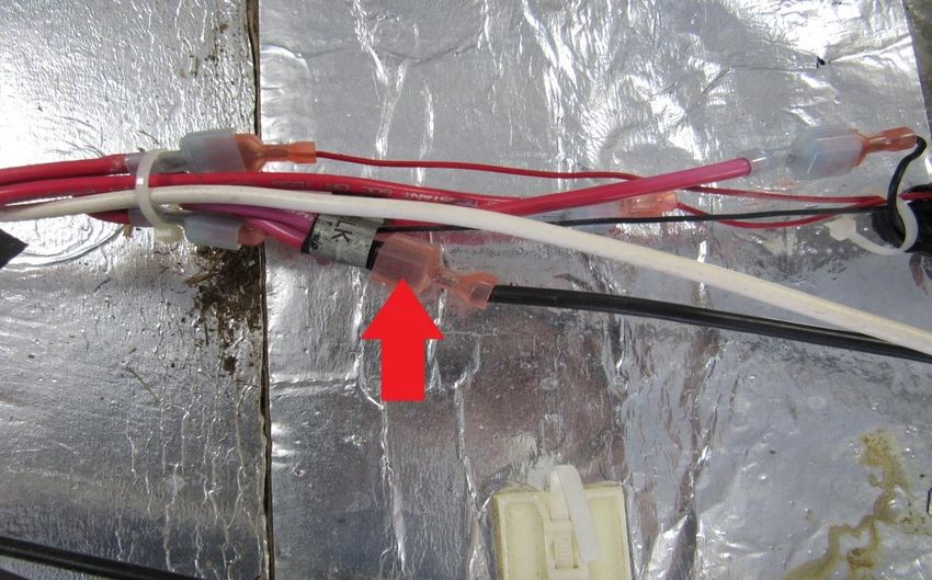
1

Good Day Friends, this is how it all begins, hope you find this helpful thru your installation.

                                                                  Units prepped for compressors

                                                         Brazed welded for strength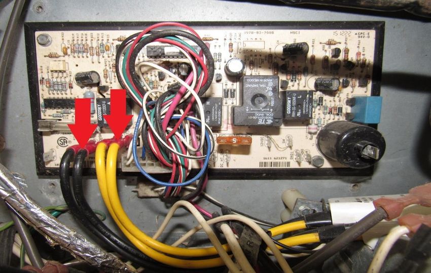
2

Tools needed to do the install:
Screw gun    5/16   ¼ Phillips wrench putty knife knife   caulk gun   zip ties

                        1 or 2
And enough time to think things thru at times, so don’t give up and hang in
there to the end it will be all worth it. A cold fridge is about to be had!!

We at JC Refrigeration try to build these as easy to install as possible, and so these are DIY cooling
units but please be aware tho that our upgrades might not look quite the same, and brackets, frames,
hole plates might not always line up perfectly as fridge boxes can vary at times, and so some
modifications, foam shaving or tweaking might need to be done at times to install it. A thing to
remember is these are made out of thick steel tube and plates so some twisting or pushing into place
is very normal and nothing to be alarmed about. We offer videos for the gas/elect and install manuals
for the Hvac units to help you thru this install and feel free to send us a picture along with your
question, and we will help you to the best of our ability.

JR & Jeremy Lambright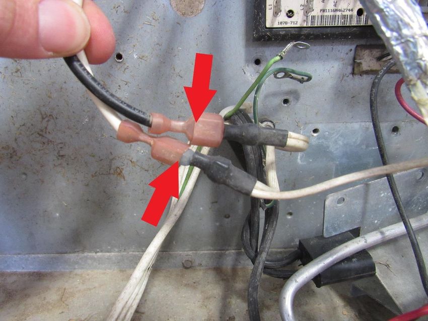
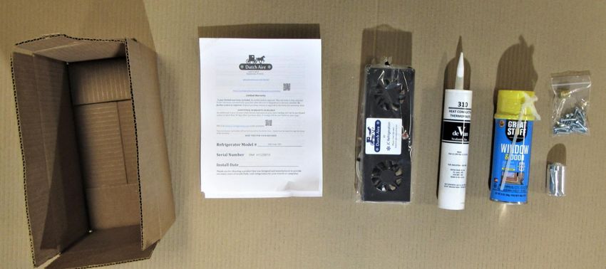
3

To start this process, begin by taking the cooling unit out of the box, if box
appears to be damaged don’t panic as we foam package them into the box (YA)
and so the box can be practically destroyed and the unit is still not damaged. So,
when you take the box apart you will notice a spray foam packing inside and so
this needs to be removed and then the unit will slide out. Inside the box you
should have the cooling unit, and parts needed to do the install (RA).
4

Cover up your floor with blankets and removing any door handles or smoke
alarms that might hinder the exit of your refrigerator from your cabinet. Turn
off the water pump (if you have an ice maker in your fridge) and the refrigerator
control panel.

       WARNING:
Make sure to turn off LP gas at the tank before starting the install.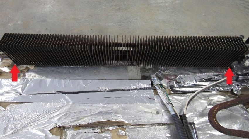
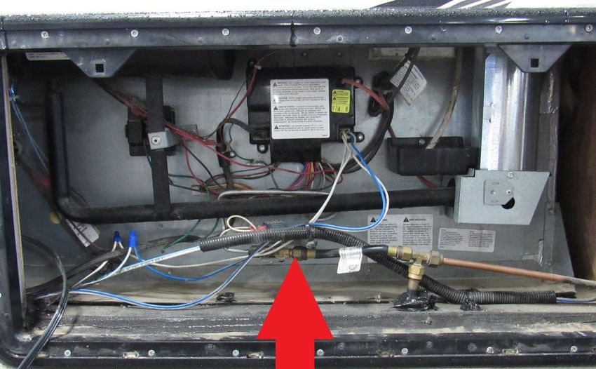
5

Locate the side vent to your refrigerator.Take the main 12V wires (RA) loose
from your board. The wire colors will vary from coach to coach. Note: If your
wire ends are not insulated, wrap the end in electrical tape so you don’t blow
the fuse.

6

Unplug your 120v plug (RA) from your RV. Location will vary from coach to
coach, if you have an icemaker unplug its cord from wall socket, making sure
water pump is turned off unscrew water supply line from solenoid (RA).
7

Using 2 wrenches remove the LP line (RA) off of the LP solenoid valve. Make
sure LP gas is turned off.
8

There are many different styles out there but most have at least 2 mounting
screws through the back plate holding the fridge to your RV floor. Screw size
and bit needed will vary from coach to coach. Remove these screws or bolts
(RA).

On Winnabago coachs you will have 4 bolts lagged to a steel side plate, 2 on
each side of the fridge, also the top roof vent cap needs to be removed and 2 to
4 philips screws need to be loosend from the top of the fridge.
9

Going inside, remove all food items and start by removing the 4 black button
covers on the top and bottom. (RA) Remove the 4 mounting screws on top and
bottom (RA). Older style fridge trim might not have the external screw buttons
but screws will still be underneath the trim after trim is removed. Screw size
and bit needed will vary from coach to coach.
10

Take a 5/16” hex bit and cordless impact driver and proceed to remove all the
screws (RA) in the freezer and the refrigerator.
11

We do not show the fridge being slid out onto the floor, as the lay out of the
coaches vary greatly and so it could be misleading to your scenario. But the
object is to have 1 guy on each side of the fridge and as your fridge starts to exit
lift up gently so when the rear end of the fridge fully exits the cavity that it does
not drop, but needs to be gently and carefully set on the floor and pushed or
carried to your open floor area. Lay fridge face down on the floor, making sure
doors are latched shut so they don’t swing open and we normally put a pile of
blankets on the floor by the top freezer door so the fridge is lying face down at
an angle.
Start by taking the LP solenoid wires loose (save these for later) (RA) and 12v
fan wires (YA) loose from the board. On 1210 style this will be shown later.
12

Take the igniter (RA) and the 120v plug (YA) loose from the board.

Remove ¼” Hex mounting screws on board (RA).
13

Remove ¼” mounting screws on LP bracket (RA).

Remove ¼” ground screw (RA).
14

Remove ¼” defrost cup screw (RA) and set cup to the side.

Remove the heating element wires from board (RA).
15

Remove the ice maker solenoid brown and white wires (RA).

Disconnect the ice maker heater wires (RA) and water supply line (YA).
16

Disconnect the 120V ice maker wires, mark these to make sure you know which
ones they are later, because these can be confused with the 12V fan wires (RA).
17

Remove the 5/16” mounting screws (RA) on the top and bottom of the unit.
18

Remove the black wire loom (RA) and cut all zip ties holding the bundle of wires
together.

Disconnect the black 12V fan wire (RA).
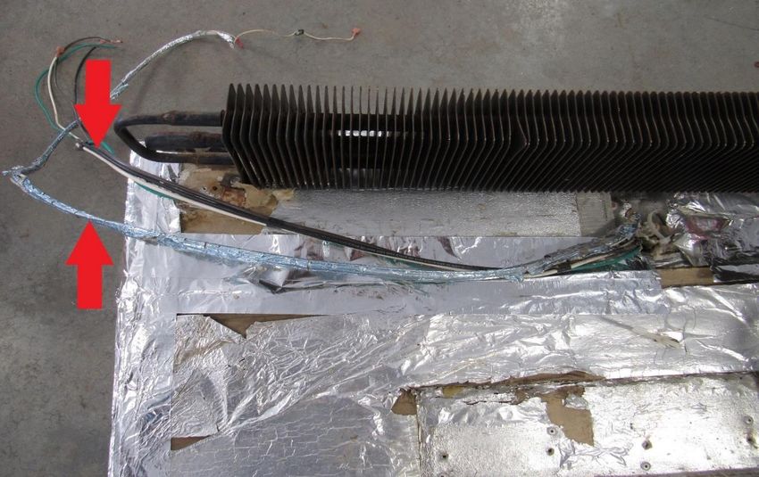
19

Disconnect the white wire (RA) from the thermal switch. This wire is red on
newer models.

Pull wires and water line up and to the side as shown (RA). Be careful with the
water line as it gets brittle with age. If you are removing the ice maker, these
can be cut and completely eliminated.
20

Leave fan wires and the black and white cords hanging over side as shown (RA).

If old unit is taped along the sides cut tape with knife (RA).
21

Take off the old cooling unit of your refrigerator by lifting straight up and out.
Clean off any residual foam or thermal sealant around the edges (RA).
22

Clean off the old thermal mastic (RA) from the freezer plates and refrigerator
fin. A large blade putty knife or scraper works well. A shop vac works well to
remove any other debris or loose foam.
23

We will now need to shift the main control board to make room for the
compressor. Remove ¼” mounting screws from board (RA). 1210 style board
does not need to be moved.

(YA) is oringal placment. Shift board left 3” as shown in picture, and secure
board (RA) using the 2 supplied 1/4” self-taping screws.
24

Remove ¼” water valve screws (RA). If you are removing the ice maker this can
be removed and left off

Shift left and reinstall the top screw (RA) in the pre-drilled hole as shown below.
25

This is how your board and wiring should look like before continuing the install.
As mentioned before, if the ice maker is being removed, all ice maker wiring,
water valve, and 120V ice maker cord can be removed and discarded. 1210 style
will look similar but the board is different size.
26

Take the fin fan out of the plastic bag. It will include two scotch locks that we
will use to hookup later.
27

Installing the fin fan has 2 options:
Option#1 Set the fin fan into the refrigerator fin opening, make sure it’s
somewhat secured to a shelve for now. Leave enough wire as shown inside and
also enough on the bottom to hook up with later. The fin fan wire will remain in
this position throughout the rest of the install.

Option #2
If you would rather install the fin fan wire thru the defrost hose later, please see
our fin fan installation manual at https://jc-refrigeration.com/wp-
content/uploads/2021/04/fin-fan-installation-website.pdf?3f35fa&3f35fa
28

Take a caulk gun and place a small bead of thermal mastic in this fashion. You
will need to use the whole tube.
29

Lay unit into box being careful so as not to scrape off any thermal mastic on the
box.
Insert defrost hose into the pre-drilled hole (RA) as shown, while lowering the
unit into the box. Make sure to keep defrost hose snug so it does not kink while
unit is being set down
30
Warning: The next few steps are very important. If done incorrectly, the
cooling unit freezer and fin screws might not line up the best. If possible, have
someone to help you with the next steps as it will make everything much easier.
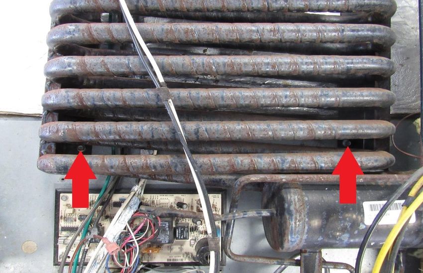
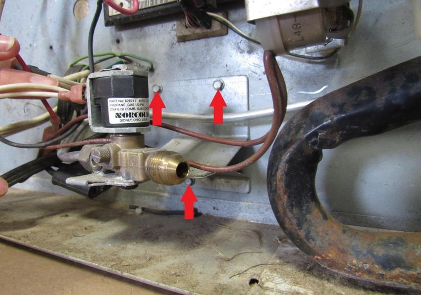
Install two 5/16” self-taping mounting screws. One on the bottom and one on
top as shown (RA). Top hole is not predrilled. This will hold the unit while its
upright. Do not be alarmed if the unit does not sit flush with the box at first.
When you fasten the mounting screws, it will pull it into place.31
Set refrigerator in upright position.
If holes are not aligned have the rear person remove the top mounting screw
and shift the unit side to side until holes are aligned, or if alone you have to set
fridge back down, take out mounting screws and adjust the unit to where the
holes line up. It does not have to be perfect, just close enough where you can
see the edge of them. Don’t be afraid to sand or shave foam off the side, top or
bottom to let the unit slide the way it needs to go to line up the freezer screws.
Pictured below is an example with the holes just visible.
Warning: The box holes can be redrilled or enlarged to make holes line up
and then the washers can cover the hole.
But do not ever drill new holes into the cooling unit plates as you will hit the
cooling tubes causing a rupture. If part of holes are visible you can either leave
them as is since unit will be sealed in the back or you can use white silicone
caulk to cover the holes.32 When holes are lined up, install all eight freezer screws (RA), using the supplied 5/16” screws in the parts bag, pulling the unit tight against the back. Do the same with the refrigerator section fin (RA). Install seven screws pulling it tight.
33

        Warning: Make sure this step gets followed precisely, otherwise your
fridge is unable to cool properly
Lay fridge back down, take the can of Great Stuff foam (shake can for a few
seconds) and apply a bead of foam around all four sides as shown below. Make
sure and seal all cracks and gaps. This will help seal all air leaks while travelling
down the road.
34 After filling all gaps with foam, follow up with covering the edges with the supplied aluminum tape as shown. This does not serve as a seal but for cosmetic purposes only.
35

On the 1200, reinstall board cover using self-drilling ¼” screws supplied,
36

On 1210 Style board connect the “limit in” spade and the “limit out spade
together using a short wire (any gauge) completing the circuit. This is where
your safety temp switch was plugged into, you will no longer need it.
37

Snip the zip tie which holds the wiring that came with the unit. You will have
three main wires coming from the control box.

They have labeled tabs on where they need to go.
38

On 1200 Style grab the two white wires that were removed prior (RA) coming
from the main control board. These need to be plugged into the wires labeled
“Gas valve wires” These 2 white wires used to go to the gas safety valve on the
old unit (Female Ends). Our controller gas valve wires have male ends (YA).

On 1210 Style board take the 2 white wires (RA) and connect to the 2 gas valve
wires.
39

Take the wire marked “Ground to fridge box” and “Igniter” and place them as
shown. Igniter simply plugs into the igniter terminal on the main control board
and the black wire with a ground terminal gets grounded out to the box.

If the fan is already prewired as shown in the picture below (RA), you can skip
pages 40 & 41
40

On the 1200 style take the white and black wires that powered your old fans
and connect the black wire to the compressor fan black as shown (RA).

1210 Style is also a black wire, but coming from a different location.
41

Secure the black wire with a zip tie (YA) to prevent accidently tearing the
connecter off.

Take the white wire (1200 style) red wire (1210 Style) that powered 12V positive
to your old fans and connect to the thermal switch as shown (RA).
42

Next, we will hook up the ice maker water line and AC 120V wires. Skip to page
47 if ice maker was removed.

The black and white coming from the ice maker go to the main 120V plug as
before.
43

The brown wire goes to ice maker water valve (RA). The white wire splits off of
the main120V plug and plugs into the ice maker water valve (YA).

You will have three ground wires coming from the main black plug, the main
white plug, and the ice maker wiring. Install a 1/4” self-taping screw shown
(RA).
44

Connect the water line to the ice maker water valve (RA).

To connect the ice maker 12V DC water line heater, start with finding these 6
wires shown in the next 3 pictures, 2 white, water valve heater wires Red Circle.
45

2 brown thermostat wires blue circle.

2 red and black 12V DC power wires coming from the board. Yellow circle, on
1210 style these are the same wires that took power to the 12V vent fans that
you just use to take power to the compressor fan, originally these had a T on
them to use for this purpose, if its missing go to your old unit and take them off
as you will need these.
46

These 6 wires need to interconnect, wires are color coded to previous pics.

Install the defrost cup as shown (RA) using a 5/16” self-taping screw.
47

Using zip ties, clean up the wiring as shown. Your wiring should look like this
when done.
48

       Warning: Please make sure and follow thru this step, otherwise unit
could over heat causing damage to the unit.
Before installing the fridge back into the cavity, check to make sure wall
insulation is secured and this is a good time to sweep or vacuum any loose
debris. If this fridge is installed into a slide out then make sure and remove the
top side vent (YA) baffling (RA), as you will no longer need this and all it will do
is slow air flow. If It’s installed into a roof vent style then nothing has to be
changed, but make sure and leave both vents open, as this unit will still have to
breathe.
49 Now you’re ready to slide the refrigerator back into the cavity. Once it’s started it helps to have someone outside to watch as you slowly push the fridge back into place, making sure the gas line is out of the way. Attach black trim pieces on top and bottom. Install mounting screws (RA)on the top and bottom.
50

Unclip the thermistor from its far-right position, and clip onto fin #21 counting
from right to left (YA), this placement is not so crucial up and down. The fin fan
needs to be attached so the fans are centered over the points of cooling which
are fin # 4 and # 20. (RA) The fin fan has a simple on/off switch in the center
(RC). Your unit will run more efficiently, and ice will not form on the fins with
the fans running at all times, if ice does accumulate to the right or left of the fan
with time the fan might need to be unclipped and moved so it’s centered over
the ice area.

Now we are ready to finish the outside. Put the two mounting screws (RA) back
in place. Or if your coach is a Winnebago, put the four bolts back in, see pic #8.
51

Plug in your 120v power cord. Keep in mind, every RV manufacturer has its own
location for this power outlet.

      WARNING: Make sure this step is properly followed and leak checked so
you don’t have a gas leak.
Thread gas plug into gas line (plug included) use wrenches to tighten in, after its
tight, gas tank is ready to turn back on and using a soap water mixture, check
for leaks. (RA) This copper tube can be bent carefully and tucked out of the way
once the fridge is back in place.
52 If your coach has an inverter you will want to plug the 120V power cord into the power outlet that is powered by your inverter. The way to determine if you have inverter power behind the fridge is to see if you have 2 separate outlets, one will be for shore power/generator and the other is always for inverter power. If they are not marked, then you need to test which is live when all other power is disconnected and the inverter is turned on. You will then leave the inverter turned on, when you plug into shore power or when the generator runs the inverter goes onto sleep mode, so when all power is disconnected and you are travelling or dry camping the inverter will turn back on and power the fridge compressor. Pics below are an example of the 2 separate outlets, if you do not have 2 outlets and yet have an inverter check this outlet as some coaches have only one outlet yet it’s powered by the inverter.
53

Plug in the 12V wires (RA) that come from your RV. The color of the wire coming
from your coach will vary from one RV to the next, and make double sure you
are putting positive to the correct pin marked 12VDC.
54

Go to the inside of your RV and turn your refrigerator control “ON” (RA) now
push the mode button (YA) and set it onto LP mode. After a few seconds your
compressor should start up and run, you can now adjust your temp setting (BA)
to your desired temp, we recommend setting it onto 4 and then after approx. 6
hrs. adjust up or down to your desired temp inside the fridge. A thing to
remember is food zone is 38F to 42F, but most times you will want this fridge to
run between 34F to 36F and in the freezer 0F to 10F.
55

We highly recommend using a digital wireless thermometer to monitor your
inside fridge temps, many phone calls or temp misleading’s can be avoided by
making sure the thermometers you are using are accurate, you do not have to
use our brand but we do recommend using something like this type.
https://jc-refrigeration.com/product/refrigerator-freezer-digital-wireless-thermometer-free-shipping/

Use digital wireless                                              DO NOT USE

Clip fridge sensor underneath second shelf down or first shelve beneath the fin,
place it center front to back and center side to side (RA), if its clipped
underneath it will be out of food containers way.
56

Same with freezer, clip underneath bottom shelves center side to side but have
this one more towards the back of the freezer.

You are all done and ready to hit the road and do some serious camping
Let us know if you see any areas we missed or that should be made clearer, since we do installs
practically every day, we get blind at times to things that should be mentioned or be made clear.

dahvac@outlook.comThanks for hanging in there to the end, give yourself a fair
pat on the back and enjoy your cold fridge for many years on your travels.
57
58

                           *Troubleshooting *
Warning Codes:
“SR”: Check your fridge ground wires and try grounding a wire from the fridge
box to your gas line.
“NO FLO” #1Check fridge ground wires. #2 Open controller cover and make sure
wires are all intact and not broken, #3 make sure the relay makes a “CLICK”
after it’s turned on. #4 Make sure igniter screw is not touching ground or wet,
turn out 1 full round. #5 Flame rectification wire may need to be changed. See
Controller below.
“NO AC” should not be turned onto “AC”, needs to be turned onto LP
59
“NO CO “Code
This code will shut down the control board and a restart is needed, see diagram below how to
restart
Make sure your thermistor has been moved to the proper location on the fin as shown in
Page 50
Make sure left hand door flapper is swinging shut and sealing to the right-hand door
Makes sure fin fan is running at all times, and compressor fan is running while the
compressor is running
If this code continues to come back wire compressor direct as seen in earlier page, this will
bypass all controls, if the fridge cools down in bypass mode the rear control needs to be
changed, if it still does not cool in the bypass mode other compressor diagnostics will have to
be done.
Restart control board
Remove board cover and remove all wires except the 12V power wires and the
gas valve wires going to the controller.
Take a 18ga or smaller wire and strip back both ends at least 1 “, make sure 12V
power and gas valve wires are hooked up, then push one end of wire in empty
slot (RA) and hold other end of wire onto a ground, either back of fridge box or
ground from coach, after approx. 5 seconds you will hear a click and you can
take wire back out and put cover back on as well as other wires and your fridge
should function as normal again.60
Thermistor check
Push and hold the “set temp” and “mode” button in at the same time after 5 seconds you will see a 1 or
88, now push the “mode” and scroll up to 3 this will then flash you your thermistor temp, this temp
should be 25 – 28 for normal food zone depending where it located on the fin, but it’s very important
that the door has been closed for at least 1 hr. before doing this test. To come back out of this mode
turn fridge off and then back on again. If you want to check the accuracy of your thermistor or vice
versus, unclip the thermistor from the fin and leave it hang into the box for approx. 1 hr with the door
closed, then do this test and the thermistor and your thermometer should match up or be close the
same.
If your controls are not operating correctly or the eyebrow seems to not be
giving fits, do this to reset all codes and this will refresh both rear and front
board.
Push and hold the “set temp” and “mode” button in at the same time after 5 seconds you will see a 1 or
88, now push the “mode” and scroll up to 6 this will then show a “ER”, then push and hold the mode
button in till a “CL” shows, let it set like this for a least 5 minutes, then shut fridge off and turn back on
and the fridge should be ready to operate again.You can also read