Jemena Electricity Networks (Vic) Ltd - 2021-26 Electricity Distribution Price Review Revised Proposal
←
→
Page content transcription
If your browser does not render page correctly, please read the page content below
Jemena Electricity Networks (Vic) Ltd
2021-26 Electricity Distribution Price Review
Revised Proposal
Attachment 04-03
Network Development Strategy - Comply with Bushfire Mitigation
Obligations at Coolaroo Zone Substation

Internal—3 December 2020

Copyright statement
    © Jemena Limited. All rights reserved. Copyright in the whole or every part of this document belongs to Jemena
    Limited, and cannot be used, transferred, copied or reproduced in whole or in part in any manner or form or in any
    media to any person other than with the prior written consent of Jemena.
    Printed or downloaded copies of this document are deemed uncontrolled.

Authorisation
Name                  Job Title                       Date              Signature

Reviewed by:

                      Customer & System Planning
                                                      3 December 20
                      Manager (acting)

                      Grid Transformation Manager     3 December 20

Approved by:

                      GM Asset Management –
                                                      3 December 20
                      Electricity Distribution

History
Rev No Date                       Description of changes                                   Author

1           03/12/2020            First issue

Owning Functional Area

Business Function Owner:          ED Asset Management

Review Details

Review Period:                    Not Applicable
NEXT Review Due:                  Not Applicable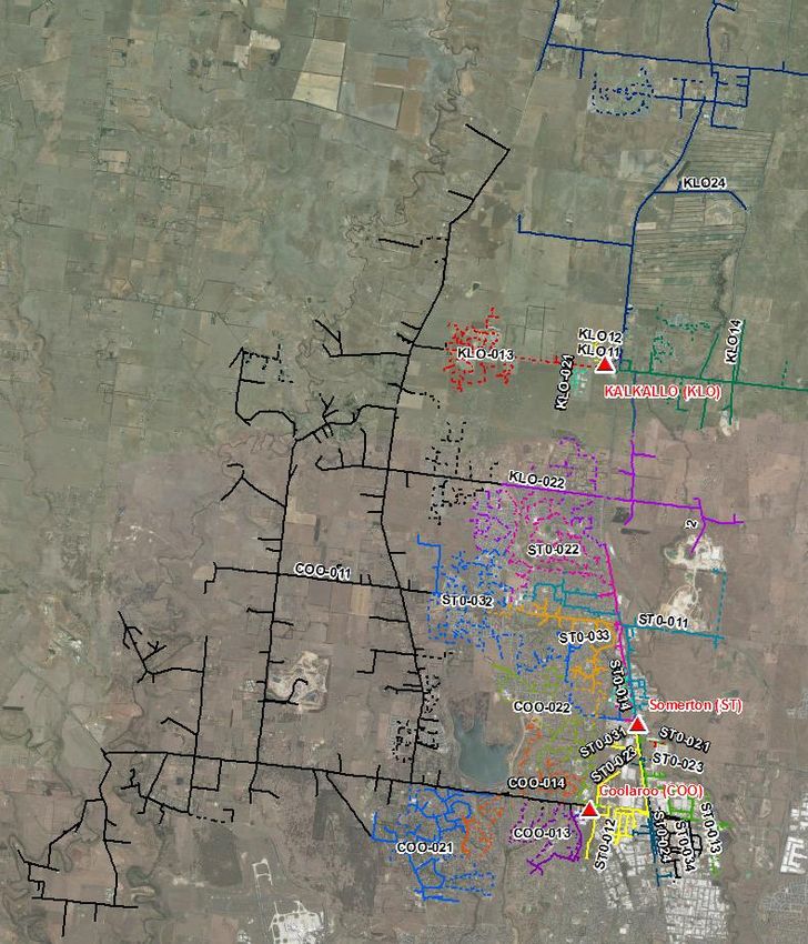
TABLE OF CONTENTS

Table of contents

Glossary.................................................................................................................................................................... iv
Abbreviations .......................................................................................................................................................... vii
Executive Summary................................................................................................................................................ viii
1.        Introduction ....................................................................................................................................................1
          1.1       Purpose .................................................................................................................................................1
          1.2       Background ...........................................................................................................................................1
          1.3       Network Overview ..................................................................................................................................4
2.        Identified Need ................................................................................................................................................8
3.        Assessment Methodology and Assumptions.................................................................................................9
          3.1       Probabilistic Economic Planning .............................................................................................................9
          3.2       Assessment Assumptions.......................................................................................................................9
4.        Options Analysis........................................................................................................................................... 11
          4.1       Options Description .............................................................................................................................. 11
          4.2       Load Forecast ...................................................................................................................................... 19
          4.3       Project and On-going Operational Costs ............................................................................................... 22
          4.4       HV Customer Cost to Comply ............................................................................................................... 23
          4.5       Network Reliability and Capacity Assessment (Unserved Energy).......................................................... 23
          4.6       Summary of Cost Analysis.................................................................................................................... 26
5.        Recommendation and Next Steps ................................................................................................................ 27
          5.1       Recommended Solution ....................................................................................................................... 27
          5.2       Next Steps ........................................................................................................................................... 27

                                                                                Internal—3 December 2020 © Jemena Electricity Networks (Vic) Ltd                                  iii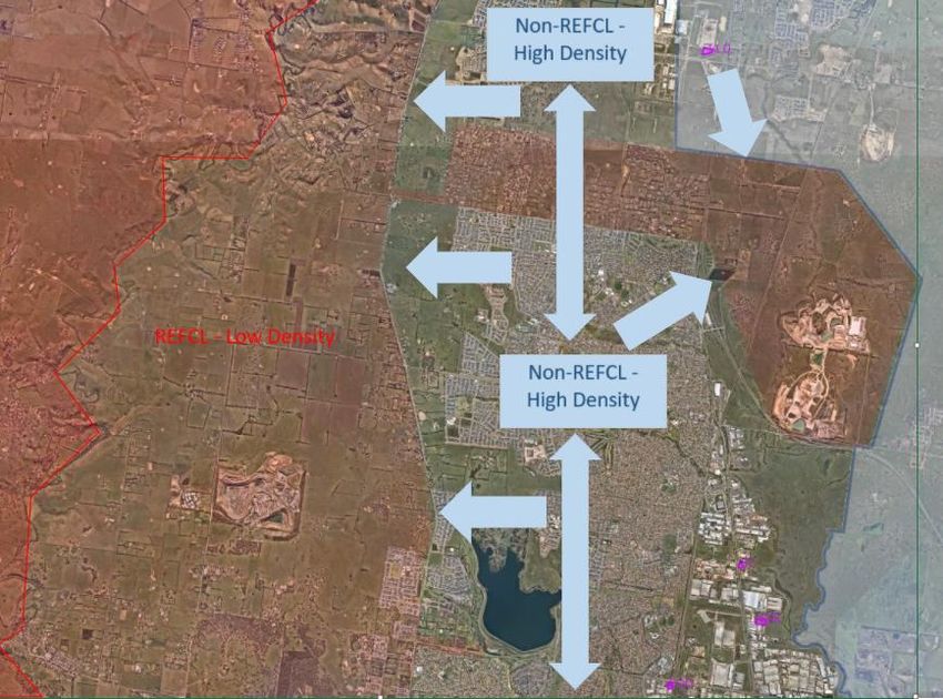
GLOSSARY

Glossary
                          Refers to a unit of measurement for the current flowing through an electrical
Amperes (A)
                          circuit. Also referred to as Amps.
Capital expenditure       Expenditure to buy fixed assets or to add to the value of existing fixed assets to
(CAPEX)                   create future benefits.
Constraint                Refers to a constraint on network power transfers that affects customer service.
                          Refers to the loss or failure of part of the network.
Contingency condition     An event affecting the power system that is likely to involve the failure or removal
(or event)                from operational service of one or more generating units and/or network
                          elements.
                          The probability that a contingency condition (or event) will occur, and typically
                          approximated by multiplying the number of times a contingency condition occurs
Contingency probability
                          (usually in a year) by its duration, normalised by the total available time (in this
                          case, a year).
Energy-at-risk            The total energy at risk of not being supplied if a contingency occurs.
                          Refers to an estimate of the long-term, probability weighted, average annual
                          energy demanded (by customers) but not supplied.
Expected unserved
energy (EUSE)             The EUSE measure is transformed into an economic value, suitable for cost-
                          benefit analysis, using the value of customer reliability (VCR), which reflects the
                          economic cost per unit of unserved energy.
                          One of five licensed electricity distribution networks in Victoria, the JEN is 100%
Jemena Electricity
                          owned by Jemena and services over 360,000 customers via an 11,000 kilometre
Networks (JEN)
                          distribution system covering north-west greater Melbourne.
Limitation                Refers to a limitation on a network asset’s capacity to transfer power.
                          The highest amount of electrical power delivered (or forecast to be delivered)
Maximum demand (MD)
                          for a particular season (summer and/or winter) and year.
Megavolt ampere           Refers to a unit of measurement for the apparent power in an electrical circuit.
(MVA)                     Also million volt-amperes.
Network                   Refers to the physical assets required to transfer electricity to customers.
                          An investment that increases network capacity to prudently and efficiently
Network augmentation      manage customer service levels and power quality requirements. Augmentation
                          usually results from growing customer demand.
Network capacity          Refers to the network’s ability to transfer electricity to customers.
                          Refers to anything potentially affecting the transfer of electricity to customers
Non-network
                          that does not involve the network.
                          A response to growing customer demand that does not involve network
Non-network alternative
                          augmentation.
Operations &
Maintenance               Expenditure (ongoing) for running a product, business or system.
expenditure (O&M)
Peak or maximum           The highest amount of electrical power delivered (or forecast to be delivered)
demand                    for a particular period of time.

                                                Internal—3 December 2020 © Jemena Electricity Networks (Vic) Ltd   iv
GLOSSARY

Probability of          The likelihood that a given level of maximum demand forecast will be met or
exceedance (POE)        exceeded in any given year:
                        Refers to an average daily ambient temperature of 32.9ºC derived by NIEIR and
10% POE condition
                        adopted by JEN, with a typical maximum ambient temperature of 42ºC and an
(summer)
                        overnight ambient temperature of 23.8ºC.
                        Refers to an average daily ambient temperature of 29.4ºC derived by NIEIR and
50% POE condition
                        adopted by JEN, with a typical maximum ambient temperature of 38.0ºC and an
(summer)
                        overnight ambient temperature of 20.8ºC.
                        A planning methodology applied to network types with the most significant
                        constraints and associated augmentation costs. It involves estimating the cost
Probabilistic method
                        of a network limitation with consideration of the likelihood and severity of
                        network outages and operating conditions.
                        Rapid Earth Fault Current Limiter or REFCL means any plant, equipment or
                        technology (excluding neutral earthing resistor) which is:
Rapid Earth Fault
                             (a) designed to reduce the effect of distribution system faults and when
Current Limiter
                                  operating as intended may lead to a REFCL condition; and
(REFCL)
                        approved by Energy Safe Victoria in an electricity safety management scheme
                        or bushfire mitigation plan pursuant to the Electricity Safety Act 1998 (Vic).
Regulatory Investment   A test administered by the Australian Energy Regulator (AER) that establishes
Test for Distribution   consistent, clear and efficient planning processes for distribution network
(RIT-D)                 investments in the National Electricity Market (NEM).
                        The measure of the ability of the distribution system to provide supply to
Reliability of supply
                        customers.

                        As prescribed by the Electricity Safety (Bushfire Mitigation Duties) Regulations
                        2018, means that in the event of a phase-to-ground fault on a polyphase electric
                        line, then network must have the ability:

                           •   to reduce the voltage on the faulted conductor in relation to the station
                               earth when measured at the corresponding zone substation for high
                               impedance faults to 250 volts within 2 seconds; and

                           •   to reduce the voltage on the faulted conductor in relation to the station
                               earth when measured at the corresponding zone substation for low
                               impedance faults to:
                               –   1900 volts within 85 milliseconds; and
Required Capacity
                               –   750 volts within 500 milliseconds; and
                               –   250 volts within 2 seconds; and

                           •   during diagnostic tests for high impedance faults, to limit:
                               –   fault current to 0.5 amps or less; and

                               –   the thermal energy on the electric line to a maximum I2t value of
                                   0.10;

                               where:

                                             Internal—3 December 2020 © Jemena Electricity Networks (Vic) Ltd   v
GLOSSARY

                        •   high impedance faults means a resistance value in ohms that is equal
                            to twice the nominal phase-to-ground network voltage in volts;
                        •   I2t means a measure of the thermal energy associated with the current
                            flow, where I is the current flow in amps and t is the duration of current
                            flow in seconds;

                        •   low impedance faults means a resistance value in ohms that is equal to
                            the nominal phase-to-ground network voltage in volts divided by 31.75;
                            and
                        •   polyphase electric line means an electric line comprised of more than
                            one phase of electricity with a nominal voltage between 1 kV and 22 kV.

                    An operating condition on the 22kV distribution system arising from the proper
                    operation of a REFCL which results in the neutral reference of the distribution
                    system moving to allow the un-faulted Phase to Earth voltage magnitude to
REFCL condition     approach a value close to the Phase to Phase voltage magnitude. The term
                    “operating condition on the 22kV distribution system‟ in this term extends up to,
                    but not beyond any device or plant which is functionally equivalent to an isolating
                    transformer.

                    The condition where no network assets are under maintenance or forced
System normal       outage, and the network is operating according to normal daily network
                    operation practices.
value of customer   Represents the dollar value customers place on a reliable electricity supply (and
reliability (VCR)   can also indicate customer willingness to pay for not having supply interrupted).
                    Refers to the location of transformers, ancillary equipment and other supporting
zone substation     infrastructure that facilitate the electrical supply to a particular zone in the
                    Jemena Electricity Network (JEN).

                                          Internal—3 December 2020 © Jemena Electricity Networks (Vic) Ltd   vi
ABBREVIATIONS
Abbreviations
Act Electricity Safety Act 1998
ASC Arc Suppression Coil
BD Broadmeadows Zone Substation
Co Network capacitive current
COO Coolaroo Zone Substation
CSIRO Commonwealth Scientific and Industrial Research Organisation
DELWP Department of Environment, Land, Water and Planning
ESV Energy Safe Victoria
EUE Expected Unserved Energy
GVE Greenvale Zone Substation
HBRA Hazardous Bushfire Risk Area
HV High Voltage
JEN Jemena Electricity Networks (Vic) Ltd
KLO Kalkallo Zone Substation
kV Kilo-Volts
LBRA Low Bushfire Risk Area
MVA Mega Volt Ampere
MVAr Mega Volt Ampere Reactive
MW Mega Watt
MWh Megawatt hour
NEM National Electricity Market
NPV Net Present Value
O&M Operations and Maintenance
REFCL Rapid Earth Fault Current Limiters
Regulations Electricity Safety (Bushfire Mitigation) Regulations 2013
ST Somerton Zone Substation
VCR Value of Customer Reliability
VEDC Victorian Electricity Distribution Code
Internal—3 December 2020 © Jemena Electricity Networks (Vic) Ltd viiEXECUTIVE SUMMARY
Executive Summary
Jemena is the licensed electricity distributor for the northwest of Melbourne’s greater metropolitan area. The
network service area ranges from Gisborne South, Clarkefield and Mickleham in the north to Williamstown and
Footscray in the south and from Hillside, Sydenham and Brooklyn in the west to Yallambie and Heidelberg in the
east.
Our customers expect us to deliver and maintain a reliable electricity supply at the lowest possible cost over the
long-term. To do this, we must choose the most efficient solution to address emerging network issues. This means
choosing the solution that maximises the present value of net economic benefit to all those who produce, consume
and transport electricity in the National Electricity Market (NEM).
Identified need
Under the Electricity Safety Act 1998 (the Act) and the Electricity Safety (Bushfire Mitigation) Regulations 2013
(the Regulations), Jemena Electricity Networks (Vic) Ltd (JEN) is obliged to ensure all 22 kV feeders originating
from its Coolaroo Zone Substation (COO) meet certain specified technical performance requirements by 1 May
2023, effectively requiring these feeders to be protected by Rapid Earth Fault Current Limiters (REFCL) or
otherwise requiring these feeders to be the subject of exemptions under the Act and the Regulations. Additionally,
JEN takes supply for three of its feeders in the nearby area from the Kalkallo Zone Substation (KLO), which is
owned by AusNet Services, and JEN must also meet the Required Capacity for its KLO feeders by 1 May 2023.
In the process of assessing and identifying viable options to provide the most economic and technically feasible
solution to maintain the long-term compliance with the Act and Regulations, JEN is also obliged to consider the
customer reliability impact (unserved energy) associated with the technical limitations of the REFCL technology,
the costs to High Voltage (HV) customers to upgrade their equipment (to enable them to continue to take supply
safely from a REFCL protected feeder in accordance with Clause 16 (c)1 of the Victorian Electricity Distribution
Code (VEDC)), and the long-term load growth and associated network augmentation requirements.
Options Considered
Recognising the interrelationships between COO and KLO, in 2019, JEN and AusNet Services engaged the
consultant WSP to assist in a joint planning exercise to examine a number of technical design options and
determine the most efficient cost of meeting the requirements of the Act and Regulations across both COO and
KLO supply areas over the long-term. This exercise identified 26 options. Through this process, we identified that
there was only one option (Option 15) which did not require any exemptions from the requirements of the Act and
Regulations. However this option involved significantly higher expenditure than other options due to significant
technical limitations of the REFCL technology.
For the reasons identified above, JEN has investigated alternative solutions to the installation of a REFCL at COO
and proposed an approach which will result in a level of residual bushfire risk that we consider is commensurate
with that which was originally intended by the Act and Regulations, but at a lower cost to customers than if no
exemptions to the Act or Regulations were granted. We considered that such alternative options would likely be
more preferable in customers’ long-term interests than Option 15 described above.
This document is based on outputs of previous joint planning report 2 prepared by the engineering consultant WSP
in December 2019 (and published as part of JEN’s regulatory proposal on 31 January 2020), and further works
undertaken by JEN since then. For the purpose of evaluating the option that maximises net market benefits, only
four credible options3 have been considered and assessed, with each option providing a commensurate level of
bushfire risk mitigation:
1
Clause 16 (c) of VEDC states that “A business customer must take reasonable precautions to minimise the risk of loss or damage to
any equipment, premises or business of the business customer which may result from poor quality or reliability of electricity supply or
the distribution system operating under the REFCL condition in accordance with clause 4.2.2A”
2
Refer to “Economic Options to Maintain REFCL Compliance at Kalkallo and Coolaroo Zone Substations, Joint Planning Report,
December 2019” report.
3
Options 7, 11 and 15 are extracted from “Economic Options to Maintain REFCL Compliance at Kalkallo and Coolaroo Zone Substations,
Joint Planning Report, December 2019” report, and re-produced in this document for information that are relevant to JEN only.
Internal—3 December 2020 © Jemena Electricity Networks (Vic) Ltd viiiEXECUTIVE SUMMARY
• Option 7 – Install Isolation Transformers On Underground Feeders and REFCLs at COO;
• Option 11 – Install REFCLs at COO;
• Option 15 – Two REFCL Zone Substations in JEN; and
• Option 27 – Build a New REFCL Zone Substation (‘GVE’)
A summary of the NPV cost analysis assessed for each option is presented in Table ES–1-1
Table ES–1-1: Summary of NPV Cost Analysis (real, $2020)
NPV of Cost
NPV of of Expected NPV of HV
Option
Project Cost NPV of O&M Unserved Customer Total Costs
($M) ($M) Energy ($M) Cost ($M) ($M) Ranking
Option 7 25.8 2.2 60.8 9.1 97.8 4
Option 11 23.6 2.2 60.2 9.1 95.1 3
Option 15 49.5 2.2 12.9 9.1 73.7 2
Option 27 35.24 2.2 13.0 1.3 51.6 1
Preferred Option
The assessment shows that the preferred solution is Option 27, as by representing the lowest total cost, this
option maximises the net economic benefit to all those who produce, consume and transport electricity in the
NEM.
Option 27 includes the following works:
• Construct a new zone substation with REFCL capability in the Greenvale area and transfer those sections of
the existing COO 22 kV network with high bushfire risk, mainly COO11, to the new zone substation – thereby
providing REFCL protection to those 22 kV feeders in compliance with the Act and Regulations; and
• Undertake various bushfire mitigation activities to reduce the bushfire risk for those polyphase electric lines
of an overhead construction within an urban environment that pose some risk to a fire ignition that could
propagate to a bushfire – therefore resulting in a bushfire risk-neutral outcome – and obtain exemptions under
the Act and Regulations in respect of these lines.5.
Option 27 provides a bushfire risk-neutral outcome when compared to the installation of REFCL protection at
COO.
JEN has lodged its exemption applications to both Energy Safe Victoria (ESV) and Department of Environment,
Land, Water and Planning (DELWP) for the above alternative solution at COO, and the exemptions from the Act
and the Regulations have been granted in November 2020.
4
Project cost for option 27 is $37.3M (real, $2021).
5
Additionally, JEN would rely on exemptions already granted under the Act and Regulations in respect of polyphase electric lin es
originating from COO which are of a fully underground construction.
Internal—3 December 2020 © Jemena Electricity Networks (Vic) Ltd ixINTRODUCTION — 1
1. Introduction
1.1 Purpose
This document describes the network development strategy adopted by JEN to comply with Section 120M of the
Electricity Safety Act 1998 together with sub-regulation 7(1)(ha) of the Electricity Safety (Bushfire Mitigation)
Regulations 2013 for the COO supply area.
It describes our process of identifying viable options to provide the most economic and technically feasible solution
to maintain the long-term compliance of COO with the Act and Regulations. It also considers the customer supply
reliability impacts associated with REFCL technical limitations, the costs to HV customers to upgrade their
equipment (to enable them to continue to take supply safely from a REFCL protected feeder in accordance with
Clause 16 (c)6 of VEDC, and the long-term load growth and associated network augmentation requirements.
The document is based on outputs of previous joint planning report 7 prepared by WSP in December 2019, and
further works undertaken by JEN since that time.
1.2 Background
The Act and Regulations requires JEN to ensure that all polyphase electric lines (22kV feeders) originating from
COO zone substation meet specified technical performance requirements in regard to conductor voltage, current
and thermal energy dissipation limits, referred to as “Required Capacity” by 1 May 2023. Additionally, JEN takes
supply for three of its feeders in the nearby area from KLO, which is owned by AusNet Services, and JEN must
also meet the Required Capacity on its KLO feeders by 1 May 2023.
In practical terms, generally, these performance requirements can be achieved through the installation of REFCLs
at the zone substation.
However, there are inherent technical limitations of REFCL that prevent a simple REFCL installation at COO,
including:
• A limit of only one Arc Suppression Coil (ASC) per 22 kV bus;
• A limit of 100A of network capacitive current (Co) per ASC due to network damping ratios. This means that
the Co for each 22 kV bus must not exceed 100A;
• A limit of 80A Co per 22 kV feeder; and
• A limit of two REFCLs per zone substation (i.e maximum zone substation Co of 200A).
COO is a two-transformer zone substation with 6 feeders, the network capacitance (Co) of each are as tabulated
in
6
Clause 16 (c) of VEDC states that “A business customer must take reasonable precautions to minimise the risk of loss or damage to
any equipment, premises or business of the business customer which may result from poor quality or reliability of electricity supply or
the distribution system operating under the REFCL condition in accordance with clause 4.2.2A”
7
Refer to “Economic Options to Maintain REFCL Compliance at Kalkallo and Coolaroo Zone Substations, Joint Planning Report,
December 2019” report.
Internal—3 December 2020 © Jemena Electricity Networks (Vic) Ltd 1INTRODUCTION — 1
Table 1-1.
Internal—3 December 2020 © Jemena Electricity Networks (Vic) Ltd 2INTRODUCTION — 1
Table 1-1: 2019 Co of COO Zone Substation 22 kV feeders
Feeder Co (A) Underground (km) Overhead (km) Comments
COO-11 105 36.7 133.3 Exceeds maximum feeder Co of 80A.
COO-12 2 0.5 0.3
COO-13 52 11.4 3.9
COO-14 51 16.5 1.4
COO-21 45 13.5 17.1
COO-22 65 21.2 0.7 Heavily loaded
TOTAL 320 99.8 156.7
It is clear from Table 1-1 that the existing 320A of Co cannot be accommodated with a simple configuration of two
REFCLs at COO zone substation, without some form of network rearrangement and significant augmentation.
Furthermore, the COO supply area forms part of the Melbourne northern growth corridor, and network Co is
forecast to increase to 410A by 2029 due to network growth, which will further exacerbate the high Co issue.
JEN and AusNet Services engaged the consultant WSP in 2019 to assist in a joint planning exercise to examine
a number of technical design options and determine the most efficient cost of meeting the requirements of the Act
and Regulations across both COO and KLO supply areas over the long-term. This exercise identified 26 options.
Through this process, we identified that there was only one option (Option 15) which did not require any
exemptions from the requirements of the Act and Regulations. However this option involved significantly higher
expenditure than other options due to significant technical limitations of the REFCL technology.
For the reasons identified above, JEN has investigated alternative solutions to the installation of a REFCL at COO
and proposed an approach which will result in a level of residual bushfire risk that we consider is commensurate
with that which was originally intended by the Act and Regulations (referred to below as a bushfire risk-neutral
outcome), but at a lower cost to customers than if no exemptions to the Act or Regulations were granted. JEN’s
proposed approach is to:
• Construct a new zone substation with REFCL capability in the Greenvale area and transfer those sections of
the existing COO 22 kV network with high bushfire risk, mainly COO11, to the new zone substation – thereby
providing REFCL protection to those 22 kV feeders in compliance with the Act and the Regulations, and
• Engage the Commonwealth Scientific and Industrial Research Organisation (CSIRO) to assess the bushfire
risk associated with those sections of the COO 22 kV feeder network that will remain supplied by COO (as a
non-REFCL zone substation) and obtain exemptions from the Act and the Regulations for these network
sections on the basis that:
– For those polyphase electric lines (or parts thereof) of an underground construction, which pose an
insignificant bushfire risk, the implementation of REFCL protection would not reduce the bushfire risk
associated with these lines – and therefore not implementing REFCL protection for these lines represents
a bushfire risk-neutral outcome;
– For those polyphase electric lines of an overhead construction within an urban environment that, following
expert assessment by CSIRO, pose no risk of a fire ignition that could propagate to a bushfire – that not
implementing REFCL protection for these lines represents a bushfire risk-neutral outcome; and
– For those polyphase electric lines of an overhead construction that pose some risk of a fire ignition that
could propagate to a bushfire, that JEN would undertake various alternative bushfire mitigation activities
to reduce this risk – therefore resulting in a bushfire risk-neutral outcome.
Internal—3 December 2020 © Jemena Electricity Networks (Vic) Ltd 3INTRODUCTION — 1
This solution (Option 27) provides a bushfire risk-neutral outcome when compared to the installation of REFCL
protection at COO.
JEN has lodged its exemption applications to both the ESV and DELWP for the above alternative solution at COO,
and the exemptions from the Act and the Regulations have been granted in November 2020.
For the purpose of demonstrating the above option (Option 27) that maximises the net market benefits (measured
in terms of total project cost, cost of expected unserved energy and HV customers cost to upgrade their equipment
to continue to take supply safely), this document only considers Options 7, 11 , 158 and 27 for COO supply area.
All other options assessed by WSP previously were considered non-credible and the proposed solutions at KLO
are independent to that of COO, thereby those ‘non-credible’ options are excluded from this assessment.
1.3 Network Overview
1.3.1 General Network Strategy
JEN has identified the areas of the COO supply network which are expected to experience urban growth in the
near future. Meanwhile, other areas are expected to remain rural and will experience low levels of growth in the
short to medium term. These differences are highlighted in Figure 1-1, where the high density non-REFCL areas
are indicated as pushing out in the direction of the blue arrows.
JEN’s overall REFCL strategy must not inhibit this future network topology.
8
Options 7, 11 and 15 are extracted from “AusNet Services and Jemena Electricity Networks, Economic Options to Maintain REFCL
Compliance at Kalkallo and Coolaroo Zone Substations, Joint Planning Report, December 2019” report, and re-produced in this paper.
Internal—3 December 2020 © Jemena Electricity Networks (Vic) Ltd 4INTRODUCTION — 1
Figure 1-1: Network Growth Strategy
1.3.2 COO Network
Single line diagrams and network area maps of COO existing network is provided below.
COO is fed from two 66 kV incoming lines and includes two 66/22kV 20/33MVA Yyn0d11 transformers, that supply
six JEN 22 kV feeders (refer to Figure 1-2).
Internal—3 December 2020 © Jemena Electricity Networks (Vic) Ltd 5INTRODUCTION — 1
Figure 1-2 COO Single Line Diagram
Source: “AusNet Services and Jemena Electricity Networks, Economic Options to Maintain REFCL Compliance at Kalkallo and Coolaroo
Zone Substations, Joint Planning Report, December 2019” report
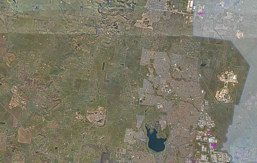
The network area fed by COO is a mix of underground and overhead feeders (Figure 1-3). The underground
feeder areas are urban and are all within the Low Bushfire Risk Area (LBRA), as depicted by the greyed areas.
COO11 represents the vast majority of the COO 22 kV network and has 36.7km of underground cable and
133.3km of overhead network, where COO 22 kV network totals are 99.8km and 156.7km respectively.
There are two HV customers within the COO LBRA, located on COO12 and BD14 (ex. COO13), and one in the
COO Hazardous Bushfire Risk Area (HBRA), on COO 11. These customers or ‘substation points’ are still subject
to the requirements of the Act and Regulations due to having been part of the COO network on the date as
specified within the Act & Regulations.
Internal—3 December 2020 © Jemena Electricity Networks (Vic) Ltd 6INTRODUCTION — 1
Figure 1-3: COO 22 kV Network Area
Source: “AusNet Services and Jemena Electricity Networks, Economic Options to Maintain REFCL Compliance at Kalkallo and Coolaroo
Zone Substations, Joint Planning Report, December 2019” report
Internal—3 December 2020 © Jemena Electricity Networks (Vic) Ltd 7IDENTIFIED NEED — 2
2. Identified Need
As outlined in Section 1.2, the primary driver of this network development strategy is to comply with the Bushfire
Mitigation Act and Regulations for the COO network area. Under section 120M of the Electricity Safety Act 1998
and Regulation 7(1)(ha) of the Electricity Safety (Bushfire Mitigation) Regulations 2013, JEN is obliged to ensure
all 22 kV feeders originating from COO have the Required Capacity by 1 May 2023.
In the process of identifying viable options to provide the most economic and technically feasible solution to
maintain the long-term compliance of COO, JEN is also obliged to consider the customer reliability impact due to
the technical limitations of the REFCL technology, costs to HV customers to upgrade their equipment to continue
to take supply safely, and the long-term load growth and associated network augmentation requirements.
Internal—3 December 2020 © Jemena Electricity Networks (Vic) Ltd 8ASSESSMENT METHODOLOGY AND ASSUMPTIONS — 3
3. Assessment Methodology and Assumptions
This section outlines the methodology that JEN applies in assessing its network supply risks and limitations for
each of the feasible option that complies or has the potential to comply with the Act and Regulations. It presents
key assumptions and input information applied to the assessments described in this document.
3.1 Probabilistic Economic Planning
In accordance with clause 5.17.1(b) of the National Electricity Rules, JEN’s augmentation investment decisions
aim to maximise the present value of the net economic benefit to all those who produce, consume and transport
electricity in the NEM.
To achieve this objective, JEN applies a probabilistic planning methodology that considers the likelihood and
severity of critical network conditions and outages. The methodology compares the forecast cost to consumers of
losing energy supply (e.g. when there is a feeder outage and it can’t be transferred to an adjacent feeder due to
the REFCL technical limitations) against the proposed augmentation cost to mitigate the energy supply risk. The
annual cost to consumers is calculated by multiplying the expected unserved energy (the expected energy not
supplied based on the probability of the supply constraint occurring in a year) by the value of customer reliability
(VCR). This expected benefit is then compared with the costs of the feasible options.
In essence, the total cost for each option would cover the following:
• Project cost to comply with the Act and Regulations by 1 May 2023;
• Annual on-going operating and maintenance expenditure (O&M) to maintain compliance;
• Present value of the annual cost of expected unserved energy over 10-year period; and
• HV customer cost to comply with the Act and Regulations by 1 May 2023.
As this strategy is developed to meet the safety regulation as the primary focus, future network augmentation
costs due to load growth under each option have not been specifically quantified, however the impacts of load
growth are factored into the annual cost of expected unserved energy considered in our analysis.
All options considered would result in the same bushfire risk-neutral safety outcome. Therefore, the option that
has the least overall cost would be considered to be the option that maximises the net economic benefit to all
those who produce, consume and transport electricity in the NEM.
JEN has not considered any non-network alternatives in this paper as a non-network solution is unlikely to be
considered sufficient to mitigate the bushfire risk.
3.2 Assessment Assumptions
In evaluating net economic benefits, the following assumptions are used to calculate the annualised value of
expected unserved energy (EUE) for all the options analysed in this paper:
– Value of Customer Reliability of $41,738 per MWh;
– Average feeder outage rate is calculated based on JEN historic data;
– Average feeder outage repair time (or supply restoration time) for underground assets is 8 hours and
overhead assets is 4 hours;
– Average feeder operational response time to perform load transfers to adjacent feeders is 1 hour;
Internal—3 December 2020 © Jemena Electricity Networks (Vic) Ltd 9ASSESSMENT METHODOLOGY AND ASSUMPTIONS — 3
– Feeder average demand is used to determine expected unserved energy at risk for a feeder outage that
cannot be transferred to adjacent feeders due to REFCL technical limitations;
– Feeder load factor of 0.55 is assumed;
– NPV is calculated over 10 years, using a real discount rate of 2.5%;
– Options 7, 11 and 15 have the same assessment outcomes in terms of technical feasibility, compliance,
risk and costs as documented in the “AusNet Services and Jemena Electricity Networks, Economic
Options to Maintain REFCL Compliance at Kalkallo and Coolaroo Zone Substations, Joint Planning
Report, December 2019” report; and
– Option 27 is technically feasible, is compliant with the Act and Regulations, and results in an acceptable
risk outcome (bushfire risk-neutral outcome).
Internal—3 December 2020 © Jemena Electricity Networks (Vic) Ltd 10OPTIONS ANALYSIS — 4
4. Options Analysis
4.1 Options Description
This section provides a summary of the scope of works for Options 7, 11, 15 and 27.
Options 7, 11 and 15 are extracted from “Economic Options to Maintain REFCL Compliance at Kalkallo and
Coolaroo Zone Substations, Joint Planning Report, December 2019” report, and re-produced in this document to
reflect the information relevant to JEN only.
4.1.1 Option 7 – Install Isolation Transformers On Underground Feeders and REFCLs at COO
This option is technically feasible and entails installing isolation transformers on underground feeders and
installing REFCLs at COO zone substation.
Option objective
This option aims to provide REFCL protection for all overhead conductors and seek exemption for all underground
cables, particularly for the sections of isolated underground cables.
Scope of works by 2023
Figure 4-1 provides a high-level overview of the scope of works.
The high level scope of works required by JEN are:
• Install 2 REFCLs at COO zone substation, including network hardening and balancing
• For COO-11 feeder:
– Underground 1.8km of overhead line on Mt Ridley Road
– Install one isolation transformer, 5 kiosks and one Ring Main Unit on Mt Ridley Road
– Install 370m of 22 kV cable
– Install two isolation transformers at the start of the underground section on Mickleham Road
• For COO-13 feeder,
– Install 2 x 170m 22 kV cable and one Ring Main Unit
– Install one isolation transformer at the start of an underground section of the feeder
• For COO-14 feeder,
– Transfer 1.4km of overhead conductor on COO-14 to COO-21
– Install two isolation transformers at the start of an underground section of the feeder
– Transfer the entire feeder to spare COO-23 CB to balance the capacitance on the COO zone substation
bus so that the REFCL constraint limits are maintained
• For COO-22 feeder,
– Underground 0.7km of overhead conductor
Internal—3 December 2020 © Jemena Electricity Networks (Vic) Ltd 11OPTIONS ANALYSIS — 4
– Install 2 kiosks
– Install two isolation transformers at the start of the feeder
• Seek exemptions under the Act and Regulations for all isolated underground cables.
Internal—3 December 2020 © Jemena Electricity Networks (Vic) Ltd 12OPTIONS ANALYSIS — 4
Figure 4-1: Option 7 High Level Scope of Works
1 Iso tx for KLO-24
2 Iso tx
for KLO- 2 REFCLSs
23 at KLO ZSS
2 Iso tx for KLO-13
2 Iso tx for KLO-21
2 Iso tx for KLO-22 1 Iso tx for KLO-14
1 Iso tx for COO-11
1 Iso tx for COO-11
1 Iso tx for COO-11 2 Iso tx for 2
2 Iso tx for COO-22 REFCLs
COO-14 at COO
ZSS
1 Iso tx for
COO-13
Internal—3 December 2020 © Jemena Electricity Networks (Vic) Ltd 13OPTIONS ANALYSIS — 4
4.1.2 Option 11 – Install REFCLs at COO
This option is technically feasible and entails installation of REFCLs at COO and transferring its underground 22
kV feeders from COO to its neighbouring Somerton Zone Substation (ST).
Option objective
This option aims to provide REFCL protection for all overhead conductors and seek exemption for all underground
cables.
Scope of works by 2023
The high level scope of works required by JEN are:
• 1.06km of new 22 kV cables to connect underground sections of COO-11 on Mt Ridley Road to KLO-22 and
one Ring Main Unit. This will transfer the supply of this underground section from COO to KLO and will assist
COO in meeting REFCL compliance by reducing the capacitance at the zone substation.
• Install 2 REFCLs at COO, including network hardening and balancing
• Transfer underground sections of COO-11, COO-13, COO-14, COO-21 and COO-22 to ST zone substation.
• Seek exemptions under the Act and Regulations for the COO feeders transferred to ST on the basis that they
are all underground cables.
Figure 4-2 provides a high-level overview of this option.
Internal—3 December 2020 © Jemena Electricity Networks (Vic) Ltd 14OPTIONS ANALYSIS — 4
Figure 4-2: Option 11 High Level Scope of Works
1 Iso tx for KLO-24
KLO non- REFCL ZSS New REFCL KLN ZSS with 2
supplying KLO-11, KLO- tx, KLO-14, KLO-24,
12, KLO-13, KLO-21 and overhead section of KLO-22
UG section of KLO-22 and cut into 66kV KLO-DRN
line
Underground and 1
kiosk for KLO-13
Overhead
section of KLO-
22 transferred to
KLN ZSS
UG KLO-22 and COO-
11 supplied from KLO
ZSS
Supply UG
sections of COO-
11, COO-13,
COO-14, COO-21
and COO-22
Transferred to
ST ZSS
2 REFCLs at COO ZSS, retain
supply of all COO feeders without
transferred sections
4.1.3 Option 15 – Two REFCL Zone Substations in JEN
This option is technically feasible and does not require any exemption to the Act and Regulations. It entails two
REFCL Zone Substations, COO and Greenvale Zone Substation (GVE) in JEN supply area. This requires one
new REFCL Zone Substation to be built in the Greenvale area.
Internal—3 December 2020 © Jemena Electricity Networks (Vic) Ltd 15OPTIONS ANALYSIS — 4
Option objective
This option aims to provide REFCL protection for all overhead conductors and underground cables.
Scope of works by 2023
The high level scope of works required by JEN are:
1 GVE REFCL zone substation scope of works
– Build a new REFCL GVE zone substation with two transformers and 2 REFCLs which will supply
COO-11 and COO-21
– New 10km of 66 kV overhead lines to supply GVE zone substation from COO
– Short sections of 22 kV underground cable and overhead line to connect COO-11 and COO-21 to
GVE zone substation
2 COO REFCL zone substation scope of works
– Install 2 REFCLs at existing COO, including network hardening and balancing
– COO retains supply to COO-12, COO-13, COO-14 and COO-22
– Transfer 4km of underground cable from COO-14 to COO-22 to balance Co on both COO 22 kV
buses within the 100A Co bus limit
Figure 4-3 provides a high level overview of this option.
Internal—3 December 2020 © Jemena Electricity Networks (Vic) Ltd 16OPTIONS ANALYSIS — 4
Figure 4-3: Option 15 High Level Scope of Works
New REFCL KLN ZSS with 2
KLO-24 south of REFCLs, KLO-14, KLO-24,
this point is and cut into 66kV STMS-KLO
supplied by KLO line
ZSS
2 REFCLs at KLO ZSS,
retain supply of KLO-11,
KLO-12, KLO-13, KLO-21,
KLO-22 and part of KLO-24
2 REFCLs at COO ZSS,
retain supply of COO-12,
COO-13, COO-14, COO-22
New REFCL GVE ZSS with 2
REFCLs, COO-11 and COO-21,
supplied by 66kV from COO ZSS
line
4.1.4 Option 27 – Build a New REFCL Zone Substation (‘GVE’)
Option objective
This option aims to:
• provide REFCL protection for all overhead conductors and some underground cables in the HBRA from the
new GVE zone substation; and
• seek exemption for all underground cables and overhead conductors within an urban environment supplied
by COO (as a non-REFCL zone substation) and undertake various bushfire mitigation activities for the
remaining overhead conductors (supplied by COO) that pose some risk to a fire ignition that could propagate
to a bushfire.
Internal—3 December 2020 © Jemena Electricity Networks (Vic) Ltd 17OPTIONS ANALYSIS — 4
By separating the current COO supply area into a low density rural area (or HBRA) to be REFCL protected and a
high density area within an urban environment to be a non-REFCL network, the capacity of COO can be fully
utilised and provide supply back-up to its neighbouring ST zone substation and Broadmeadows Zone Substation
(BD) – the reverse also applies. This arrangement would allow JEN to avoid a decrease in network reliability
levels for customers in the COO and neighbouring ST and BD supply areas.
Scope of works by 2023
This option is technically feasible and includes the following works:
• Construct a new zone substation with REFCL capability in the Greenvale area and transfer those sections of
the existing COO 22 kV network with high bushfire risk, mainly COO11, to the new zone substation – thereby
providing REFCL protection to those 22 kV feeders in compliance with the Act and the Regulations, and
• Engage CSIRO to assess the bushfire risk associated with those sections of the COO 22 kV feeder network
that will remain supplied by COO (as a non-REFCL zone substation) and obtain exemptions from the Act and
Regulations for these network sections on the basis that:
– For those polyphase electric lines (or parts thereof) of an underground construction, which pose an
insignificant bushfire risk, the implementation of REFCL protection would not reduce the bushfire risk
associated with these lines – and therefore not implementing REFCL protection for these lines represents
a bushfire risk-neutral outcome;
– For those polyphase electric lines of an overhead construction within an urban environment that, following
expert assessment by CSIRO, pose no risk of a fire ignition that could propagate to a bushfire – that not
implementing REFCL protection for these lines represents a bushfire risk-neutral outcome; and
– For those polyphase electric lines of an overhead construction that pose some risk to a fire ignition that
could propagate to a bushfire, that JEN would undertake various alternative bushfire mitigation activities
to reduce this risk – therefore resulting in a bushfire risk-neutral outcome.
This solution therefore provides a bushfire risk-neutral outcome when compared to the installation of REFCL
protection at COO.
JEN has lodged its exemption applications in May 2020 to both the ESV and DELWP for the above alternative
solution at COO, and the exemptions from the Act and the Regulations have been granted in November 2020.
This proposed option is most aligned with JEN’s general network strategy for the area detailed in Section 1.3.1
and as provided in Figure 4-4.
Internal—3 December 2020 © Jemena Electricity Networks (Vic) Ltd 18OPTIONS ANALYSIS — 4
Figure 4-4: Option 27 – Proposed GVE Zone Substation
Non-REFCL -
High Density
Remote
REFCL
REFCL - Low Density
Non-REFCL -
High Density
GVE
4.2 Load Forecast
This section presents the maximum demand forecast at COO, neighbouring ST and the new GVE zone
substations prior-to- and post- REFCL augmentation work under each option and compares them to the station
ratings. In doing so, it indicates whether the proposed REFCL augmentation under each option caters for the load
growth requirement over the next 10 years or whether it requires further augmentation to meet the projected
growth in the area.
This assessment supports us in determining the most efficient outcome in the long-term interests of JEN’s
customers.
Table 4-1 and Table 4-2 present the ratings of existing COO and ST zone substations respectively – these ratings
remain the same prior-to- and post- REFCL augmentation work.
Table 4-1: COO Zone Substation Ratings
Summer Winter
Substation N Secure Rating (MVA) 47.6 47.6
Substation N-1 Rating (MVA) 38.0 39.6
Internal—3 December 2020 © Jemena Electricity Networks (Vic) Ltd 19OPTIONS ANALYSIS — 4
Table 4-2: ST Zone Substation Ratings
Summer Winter
Substation N Secure Rating (MVA) 95.2 95.2
Substation N-1 Rating (MVA) 79.7 89.3
Table 4-3 presents the maximum demand forecast for COO zone substation for the forward 10-year planning
period.
Table 4-3: COO Zone Substation Demand Forecast Prior to REFCL Augmentation
2020
2021 2022 2023 2024 2025 2026 2027 2028 2029 2030
(actual)
Summer –
10% POE 43.7 49.4 51.0 52.1 52.7 53.2 53.5 53.5 53.9 54.2 54.2
(MVA)
Summer –
50% POE 43.7 43.0 44.4 45.3 46.0 46.5 46.4 46.7 46.9 47.2 47.4
(MVA)
Based on the above forecast, there is insufficient capacity at COO zone substation to supply the area in the
forward 10-year planning period, meaning action (most likely augmentation work given the size of this constraint)
will be required to alleviate the emerging capacity constraint to meet on-going load growth.
Table 4-4: ST Zone Substation Demand Forecast Prior to REFCL Augmentation
2020
2021 2022 2023 2024 2025 2026 2027 2028 2029 2030
(actual)
Summer – 10%
76.4 82.0 83.4 83.9 83.3 83.3 84.1 84.3 85.2 85.9 86.1
POE (MVA)
Summer – 50%
76.4 75.1 76.6 77.0 76.6 76.7 76.9 77.6 78.2 78.8 79.5
POE (MVA)
Based on the above forecast, there is sufficient capacity at ST zone substation to supply the area in the forward
10-year planning period. However, it should be noted that the station is fully utilised. Beyond 2030, JEN will likely
need to consider some form of augmentation or alternative non-network solution to alleviate the emerging capacity
constraint to meet on-going load growth.
Internal—3 December 2020 © Jemena Electricity Networks (Vic) Ltd 20OPTIONS ANALYSIS — 4
4.2.1 Load Forecast for Option 7
Under Option 7, the maximum demand forecasts for COO and ST zone substations over the forward 10-year
planning period remain the same. Based on this outcome, there is likely a need for further augmentation at COO
to meet the load growth requirement within the forward planning period.
Due to the complexity in the REFCL technical limitations and supply arrangements between REFCL and non-
REFCL supply areas, the future network augmentation scope and cost for load growth have not been quantified.
However, we have factored this load growth impact in the annual cost of expected unserved energy in Section
4.5.
4.2.2 Load Forecast for Option 11
Under Option 11, it is expected that there will be a net load transfer from COO to ST of approximately 11MVA
from summer 2024 onwards. This results in the demand reduction at COO, which will likely mean avoiding any
augmentation work to meet load growth requirement within the forward 10-year planning period. However, the
increase in demand at ST would necessitate augmentation work or alternative non-network solution to address
the emerging capacity constraint within the forward planning period.
Due to the complexity in the REFCL technical limitations and supply arrangements between REFCL and non-
REFCL supply areas, the future network augmentation scope and cost for load growth have not been quantified.
However, we have factored this load growth impact in the annual cost of expected unserved energy in Section
4.5.
Table 4-5 presents the maximum demand forecast for COO zone substation for the forward 10-year planning
period.
Table 4-5: COO Zone Substation Demand Forecast Post REFCL Augmentation (Option 11)
2020
2021 2022 2023 2024 2025 2026 2027 2028 2029 2030
(actual)
Summer – 10%
43.7 49.4 51 52.1 41.7 42.2 42.5 42.5 42.9 43.2 43.2
POE (MVA)
Summer – 50%
43.7 43 44.4 45.3 36.4 36.9 36.8 37.1 37.3 37.6 37.8
POE (MVA)
Table 4-6 presents the maximum demand forecast for ST zone substation for the forward 10-year planning period.
Table 4-6: ST Zone Substation Demand Forecast Post REFCL Augmentation (Option 11)
2020
2021 2022 2023 2024 2025 2026 2027 2028 2029 2030
(actual)
Summer – 10%
76.4 82 83.4 83.9 94.3 94.3 95.1 95.3 96.2 96.9 97.1
POE (MVA)
Summer – 50%
76.4 75.1 76.6 77 86.2 86.3 86.5 87.2 87.8 88.4 89.1
POE (MVA)
Internal—3 December 2020 © Jemena Electricity Networks (Vic) Ltd 21OPTIONS ANALYSIS — 4
4.2.3 Load Forecast for Options 15 and 27
Under Options 15 and 27, it is expected that there will be a net load transfer from COO to the new GVE of
approximately 15MVA from summer 2024 onwards. This results in the demand reduction at COO, which will avoid
any augmentation work to meet the load growth requirement. The new GVE zone substation will also have
sufficient capacity to meet the on-going load growth over the forward 10-year planning period.
There is no change to ST demand forecast.
Table 4-7 presents the maximum demand forecast for COO zone substation for the forward 10-year planning
period.
Table 4-7: COO Zone Substation Demand Forecast Post REFCL Augmentation (Options 15 & 27)
2020
2021 2022 2023 2024 2025 2026 2027 2028 2029 2030
(actual)
Summer – 10%
43.7 49.4 51 52.1 37.7 38.2 38.5 38.5 38.9 39.2 39.2
POE (MVA)
Summer – 50%
43.7 43 44.4 45.3 32.9 33.4 33.4 33.6 33.8 34.1 34.3
POE (MVA)
Table 4-8 presents the maximum demand forecast for GVE zone substation for the forward 10-year planning
period.
Table 4-8: GVE Zone Substation Demand Forecast Post REFCL Augmentation (Options 15 & 27)
2020
2021 2022 2023 2024 2025 2026 2027 2028 2029 2030
(actual)
Summer – 10%
0 0 0 0 15.0 15.0 15.0 15.0 15.0 15.0 15.0
POE (MVA)
Summer – 50%
0 0 0 0 13.1 13.1 13.0 13.1 13.1 13.1 13.1
POE (MVA)
4.3 Project and On-going Operational Costs
Based on the scope of works provided in Section 4.1, the project costs for each option is summarised in Table
4-9 below.
Table 4-9: Project Costs (real, $2020)
Option 7 Option 11 Option 15 Option 27
Project capital cost ($M) 27.1 24.7 51.9 36.9
NPV of project capital 25.8 23.6 49.5 35.2
cost ($M)
Internal—3 December 2020 © Jemena Electricity Networks (Vic) Ltd 22OPTIONS ANALYSIS — 4
The on-going annual O&M expenditure of REFCL compliance testing for each option is estimated at $306.2
thousand per annum (real, $2020). Applying the real discount rate of 2.5% per year, the present value of this
expenditure over the ten-year assessment period equates to $2.2M.
4.4 HV Customer Cost to Comply
In determining the option that maximises the net economic benefit to all those who produce, consume and
transport electricity in the NEM, JEN also considers the cost to HV customers within COO supply area required
to upgrade their equipment to continue to take supply safely9.
Following our discussions with a HV customer connected to COO in early 2020, they’ve indicated that the total
cost to upgrade both their HV substations in Roxburgh Park and Coolaroo to the Required Capacity is estimated
at $8M. JEN also has a third HV customer connected within the COO supply area that also require to meet the
Required Capacity. For this HV customer, we assume that an isolation transformer will be used to meet the
compliance and is estimated at $1.3M.
Table 4-10 presents a summary of the HV customers cost under each option.
Table 4-10: HV Customer Cost to Comply within COO Supply Area ($M, real 2020)
HV Customer Cost to Comply Option 7 Option 11 Option 15 Option 27
HV Customers 1 & 2 8 8 8 0
HV Customer 3 1.3 1.3 1.3 1.3
Total HV Customers Cost 9.3 9.3 9.3 1.3
Total NPV of HV Customers Cost 9.1 9.1 9.1 1.3
4.5 Network Reliability and Capacity Assessment (Unserved Energy)
The complexities and technical limitations associated with REFCL equipment can introduce a number of
constraints during network operations—for example, by limiting our ability to undertake emergency load transfers
between feeders—that may lead to significant supply interruptions under some circumstances. The following table
summarises an assessment of the impact on the affected feeders for each proposed option, in terms of prolonged
customer supply interruptions (unserved energy) during unplanned outages affecting customer supplies reliability.
It also summarises the impact on network capacity for COO, where significant urban growth is expected in the
mid-term.
9
Clause 16 (c) of VEDC states that “A business customer must take reasonable precautions to minimise the risk of loss or damage to
any equipment, premises or business of the business customer which may result from poor quality or reliability of electricity supply or
the distribution system operating under the REFCL condition in accordance with clause 4.2.2A”
Internal—3 December 2020 © Jemena Electricity Networks (Vic) Ltd 23OPTIONS ANALYSIS — 4
Table 4-11: Prolonged customer supply interruptions (unserved energy) summary for each option
Single Contingency
Event Option 7 Option 11 Option 15 Option 25
Feeder COO-11 100% of customers 100% of customers Reliability risk reduced Reliability risk reduced
cannot be transferred cannot be transferred to 1/3 compares with to 1/3 compares with
to COO-21 because of to COO-21 because of Options 7 & 11 Options 7 & 11
COO Bus #2 COO Bus #2 because COO-11 is because COO-11 is
capacitance limit, until capacitance limit, until split into 3 feeders, split into 3 feeders,
fault is repaired fault is repaired reducing exposure by reducing exposure by
2/3 2/3
Feeder COO-12 100% of customers 100% of customers 100% of customers 100% of customers
cannot be transferred cannot be transferred can be transferred to can be transferred to
to COO-11 due to to COO-11 due to COO-11 COO-11 or ST-12
thermal capacity limit thermal capacity limit
Feeder COO-13 70% of customers 70% of customers 100% of customers 100% of customers
cannot be transferred cannot be transferred can be transferred to can be transferred to
to COO-11 or ST-31 to COO-11 or ST-31 COO-11 COO-11 or BD-14
because of because of
capacitance limit capacitance limit
(80A) on COO-11 and (80A) on COO-11 and
thermal capacity limit thermal capacity limit
on ST-31, until fault is on ST-31, until fault is
repaired repaired
Feeder COO-14 25% of customers 50% of customers No customer is at risk No customer is at risk
cannot be transferred cannot be transferred with prolonged with prolonged
to adjacent feeders. to COO-22, ST-31 or outage, as there are outage, as there are
Isolation transformer ST-32 because of likely to be transfers to transfers to COO-21,
provides 75% of capacitance limit on adjacent feeders on COO-22, GVE-12 and
customer transfer to COO Bus #2 and the same bus. GVE-13.
COO-22 and ST-32 thermal capacity limit
on ST-31 and ST-32,
until fault is repaired
Feeder COO-21 100% of customers 100% of customers No customer is at risk No customer is at risk
cannot be transferred cannot be transferred with prolonged with prolonged
to adjacent feeders to adjacent feeders outage, as there are outage, as there are
COO-11 or COO-14, COO-11 or ST-31, likely to be transfers transfers available to
due to capacitance due to capacitance available to adjacent COO-11, COO-14,
limit on COO-11 or limit on COO-11 or feeders on the same GVE-11, GVE-12 and
COO-14 as non- ST-31 being a non- bus. GVE-13
REFCL via isolation REFCL feeder
transformer
Feeder COO-22 25% of customers 50% of customers No customer is at risk 25% of customers
cannot be transferred cannot be transferred with prolonged cannot be transferred
to adjacent feeders. to adjacent feeders outage, as there are to adjacent feeders –
Isolation transformer due to capacity limit likely to be transfers 75% transfers
provides 75% of on ST-31 and ST-32. available to adjacent available to COO-14
and ST-32, and
indirect transfers to
Internal—3 December 2020 © Jemena Electricity Networks (Vic) Ltd 24You can also read