June 2020 - Model Flying NZ
←
→
Page content transcription
If your browser does not render page correctly, please read the page content below
June 2020


June 2020 Page 1

Editor
Murray Race Model Flying New Zealand Council Contents
6 Stevenson Street 3 Council Report
Ph: 03 418 0969 President 4 AGM Notice
Mobile: 027 418 0969 Len Drabble 5 Choosing the Right Electric Power Part 2
Balclutha 9230 6 E36 Why You Must Fly One
04 526 2622 Simple Wing Bags
race.m@xtra.co.nz 8
President@modelflyingnz.org 9 DB Ghost Rider
12 Using Cardboard Tubes For Storage
Advertising Manager 13 Foam Board Fun
Vivienne Race 13 Piggy Back
Ph: 03 418 0969 Secretary 14 A Tiger With Only One Wing
v.race@xtra.co.nz Jonathan Shorer 15 Home Detention
16 A Hobby For All Seasons
Copy Deadlines 21 Emma Drive 17 Low Cost Battery Backup System
RD31 Levin 5573 19 Snipe 2/2 Electric F5K
March Issue
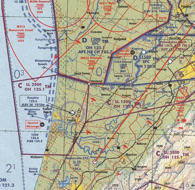
027 225 1952 20 Civil Aviation Rules For Aeromodellers Part 2
31st January 22 Builds
Secretary@modelflyingnz.org
June Issue 23 Building Your Own Flight Box
25 How Fast Was That?
23rd April Treasurer 27 New Plymouth MAC Annual Memorial Fly-in
September Issue 30 My Trip To The Tucson Aerobatic Shootout
24th July 31 Brazil/Argentina 2020
32 Reflections On The 72nd Nationals
December Issue 33 Rees Jones Memorial Fly-in
23rd October 35 Hawkes Bay Glider Tow
37 Pylon SIG
39 Vintage SIG
Front Cover Northern North Island 47 Control Line SIG
Chris Jackson 48 Soaring Scribe
Frazer Brigg’s Sig Cadet seems 021 0729 458 50 Free Flight SIG
to be heading for the moon in this 51 NDC Report & Results
dramatic shot at the New
NNIRep@modelflyingnz.org Classifieds
55
Plymouth Memorial Fly-in early
March.
Central North Island
Frazer Briggs Special Interest Groups
CNIRep@modelflyingnz.org Pylon Aerobatics
John Danks Frazer Briggs
Ph 09 432 2071 021 288 9455
theteam@airsail.co.nz frazer@pbgsoftware.co.nz
Southern North Island LMANZ Control Line
Graham Job Hamish Loveridge Dave Thornley
hamishloveridge@hotmail.com Ph 07 349 3719
027 357 5638 027 460 3848
SNIRep@modelflyingnz.org Free Flight
Large Model Co-Ordinator Rob Wallace
Rene Redmond Ph 06 878 4993
Ph 06 356 5861 ffonzrjw@gmail.com
largemodelpermits@
Northern South Island modelflyingnz.org Free Flight &
The Opinions expressed in this Dave Griffin
publication are not necessarily Control Line Scale
those of the editor or 021 352 595 Radio Control Scale Ricky Bould
Model Flying New Zealand. NSIRep@modelflyingnz.org Gwyn Avenell Ph 09 478 8949
Ph 09 298 4819 unimec1994@gmail.com
Neither this publication nor avenellsnz@gmail.com
MFNZ are responsible for the Helicopter
contents or services advertised Soaring Allen James
within these pages.
Southern South Island David James 027 580 5630
Daniel Munro Ph 06 354 3452 allenjames@orcon.net.nz
All advertising is accepted 027 474 3316 nzsoaringtc@hotmail.com
on the integrity of those SSIRep@modelflyingnz.org Vintage
placing the advertising. NZ Jet Turbine Don Mossop
Craig Abbott 07 578 9783
Printed by president@NZJMA.com donmossop@gmail.com
Fisherprint Ltd
Competitions Manager FPV & Multirotors
Kevin Botherway Mathew Wellington
mat_wellington@yahoo.co.nz
027 5570 470
CompMan@modelflyingnz.org
Recording Officer
Allan Knox
recordingofficer@modelflyingnz.org
Administration/Membership Manager
Paul Clegg
The body Governing 021 986 566
Model Aeronautics in New Zealand members@modelflyingnz.org
Recognised by
The Royal New Zealand Aero Club (Inc)
New Zealand Representatives of the F.A.I
Page 2 Model Flying World
Council Report                          Anyone got a little bit of space?
                        Who would have thought, when we wrote
                        three months ago in the last magazine, that         I’ve been giving a home to some of the interesting bits of
                        we should be kind to each other at the club, it     MFNZ history for a while now and with my imminent
                        would become the National anthem to get us          departure, they need a new home. It is records and such
                        through the Covid-19 crisis? Emotions have          going back to the formation of NZMAA so it just needs
run high as we’ve envisaged a terrible disaster whilst others have          somewhere dry. Have you got space?
disparaged precautions about “just another flu”. By the time you are
reading this, club flying will have returned to near normal and the
strengths of camaraderie and companionship will have been
reaffirmed.

So what have we learned? So far, membership renewals are on track
and cards are being distributed. We are experimenting with this issue
of the magazine being primarily digital and looking at the implications.
It is hard to second guess or even first guess what Government rules
mean when applied to model flying. There is no right answer to how
best to communicate with clubs and members, someone will always
think they have a better solution. Modellers are very practical and will
turn an inconvenient isolation into a mega opportunity for building and
refurbishing.

You will find elsewhere in the Magazine, the notice regarding the AGM.
We plan to hold a physical meeting in Wellington at the Miramar golf
club next to the airport. We will not be having a SIG meeting on the
same day. Please register proxy votes if you are not planning to            Contact secretary@modelflyingnz.org and we can
attend.                                                                     arrange delivery.

                                    External Affairs
                            Our principle contacts are with the CAA and
                            the Ministry of Transport. Having got to know
                            the three person team at the Ministry of
                            Transport working on new drone regulations,
                            we heard at Christmas that 2 of them were
moving to other jobs. We have met replacements but had no chance to
brief them about the difference between a model aeroplane and a
flying taxi. They are all working from home so it may be some time
                                                                            Never too young to get them into it
before we can explain to them why rules need to be crafted carefully
rather than being “sweeping”. We saw examples during the release of
Alert Level rules that this message never gets tired and needs frequent
repetition.

At CAA, they have been under a cloud for some time. There were
allegations that the place had a poor work culture and a Ministerial
investigation was conducted to examine complaints of workplace
bullying. The report is not yet announced but this period has been
overlapped by a comprehensive reorganisation. The changes to top
level staff have been completed but the levels at which we conduct
normal business have not been announced yet. They were due after
Easter but lockdown got in the way and should be public in July.
Against this background they have a funding problem. CAA gets about
80% of its’ revenue from the Air passenger levy. So every time you fly,
part of your airfare is heading down to Asteron House to fund the CAA.
But not for the past two months and not much for the next many months
or years. Reorganisation, lack of funding and a Ministerial review are
not an ideal working base. A short while ago, the Director Graeme
Harris, who I have worked with for 7 years, resigned with immediate
effect and the Deputy Director Janine Hearn went on indefinite leave.
However we emerge from the Covid-19 crisis, working with CAA is
going to be different.
Farewell.

After living in New Zealand for 12 years and being on the MFNZ
Council for almost 9 years, my wife and I have decided to move back to
UK to be nearer to our children and grandchildren. It has been a              Here is a photo of my boy Patrick (who is 2) in
fantastic OE for us but now it is time for a new chapter. We haven’t
chosen the easiest time for such a big move but we’ll figure it out step
                                                                              bed reading the December issue of Flying
by step. I will have lots of memories of brilliant clear blue skies and       World.
some terrific modelling friends. Cheerio and thank you one and all.
                                                                              Hamish Loveridge

June 2020                                                                                                                          Page 3
ANNUAL GENERAL MEETING
                    Miramar Golf Club, Wellington Airport                                               FREE
                    Saturday 4th July 2020 at 10am                                                     Parking
  Agenda:                             Council Officers for 2020/21:                   How can I vote?
  1. Apologies for absence            1. President             Len Drabble          1.By attending in person.
  2. Roll call                        2. Secretary             Vacant               2.By sending in the form in this
  3. Minutes of previous meeting      3. Treasurer             Vacant                 magazine electronically or surface
  4. Matters arising                  4. Competition Manager Kevin Botherway          mail to the Secretary.
  5. Presidents report                5. Northern North Island Chris Jackson        3.By using the form in this magazine
  6. Treasurers report                6. Central North Island  Frazer Briggs          to nominate a proxy holder to vote on
  7. 2021/2022 Budget                 7. Southern North Island Graham Job             your behalf. All forms must be with
  8. Review of 2019/2020 accounts     8. Northern South Island Dave Griffin             the Secretary five (5) days before the
  9. Subscriptions for 2021/2022      9. Southern South Island Daniel Munro           meeting.
  10. Election of Council members
  11. Motions to be considered       At the time of publication of the magazine there are no contested positions on the
  12. General business               Council and no Notices of Motion. Proxy votes are needed for the purposes of
                                     establishing a quorum.

                 PROXY VOTING FORM
    FOR THE MFNZ/NZMAA ANNUAL GENERAL MEETING
             BEING HELD ON 4th JULY 2020
  To: Paul Clegg, Administrator of MFNZ/NZMAA                  Please send your completed form to the Administrator,
                                                               members@modelflyingnz.co.nz not later than 5 days before
  (Postal & email address as per Web & Model Flying World)     the day of the meeting

  Dear Sir,

  I, (print full name)

  being member number                  of

  MFNZ/NZMAA hereby nominate (print name)

  to vote on my behalf at the MFNZ/NZMAA Annual General Meeting on 4.7.2020.

  Signed                                              Date

     I accept the nomination as proxy holder

     (print full name)

     Member No.             Signed                           Date               Contact number

                                                                                                    For        Against
                   Remit 1. That Bill McGarvey be made a Life member of the Association.
 Notices                    Proposed Rex Bain
   of                                                                                               For       Against
 Motion            Remit 2. That Jonathan Shorer be made a Life member of the Association.
                            Proposed Len Drabble

Page 4                                                                                                    Model Flying World
Having selected the combination suggested it is now just a case of
                                                                              double-clicking the selection and the program will enter all the data into
                                                                              propCalc where you can fiddle with many of the parameters to your
                                                                              hearts content.
                                                                              Here is a selection of the performance data available.

Perhaps you wondered if there is an even easier way to get a range of
power system options for that new plane you are building or buying?
What about using one of the “Calculator” programs that are available?
In this part of the article I will be using eCalc program and in particular
seeing if their setupFinder tool provides the same result as we
achieved using the manual method.

                                   propCalc             setupFinder

Choose your Calculator             Calc                   Calc
                                  for Airplane          for Airplane

(eCalc is not a free program but is reasonably priced- pay US$2.50 for
a month to use it for a new project or about US$7.00 for a year)
                                                                              The dials give a quick overview and if you have chosen values outside
In our previous example we had a sports plane weighing 5 lbs (2.3Kg)
                                                                              the manufacturers published data you will be indicating in the red
requiring about 750 Watts of power. If we use setupFinder we will need
                                                                              areas. (Load indicated above relates to battery C rating)
to know details about our plane such as overall weight, wingspan and
wing area. We will also need to choose the number of cells for our
                                                                              In conclusion, whatever method you use to chose your new power
battery and the typical flight time we would like to achieve. In our
                                                                              system the proof that you have made good choices will be at the flying
previous example we also limited the prop diameter to 11 inches to give
                                                                              field.
ample ground clearance. Some fields in the input screen can have a
low value if you want the program to provide a larger number of
                                                                              However before your first flight remember to check the current and
options.
                                                                              watts at 100% throttle with your trusty power meter before you head for
Here is what I entered for our example.
                                                                              the sky.

The burning question then is our previous choice of motor and prop combination amongst the many
options that the program suggested from its database?
We chose a Cobra C3520/10 980Kv motor with a 11x 7 APC e prop.

Here are the Cobra offerings from the program

June 2020                                                                                                                                      Page 5
• For trimming you will need
                                                                                o a number of small wedges 1/8” x ½” trailing edge stock is
                                                                                    good,
                                                                                o small ply pieces (1/32 ply or smaller)for packing
                                                                                o Cyno or double sided tape

                                                                            Flight Pattern
                                                                            The flight pattern we want is a fast right hand spiral climb, a right hand
                                                                            transition that rolls into a glide keeping the nose up without a stall, and
                                                                            a slow right hand glide. The climb is right turn balanced by a left roll.

          36
                                                                            Each part of the flight can be considered separately but as these
                                                                            models are fixed surface any trim changes made will affect all
                                                                            elements of the flight.
               Why You                                                                                                    The real challenge with
                                                                                                                          free flight is that after the
               Must Fly One!                                                                                              model leaves your hand it
               Kevin Barnes                                                                                               is completely out of your
                                                                                                                          control – all the trim
                                                                                                                          settings are made before
                                                                                                                          launch.

                                                                                                                          Initial Flights.
                                                                                                                          By now your heart should
                                                                                                                          be pumping. It is exciting
                                                                                                                          to test a new model for the
                                                                                                                          first time! And also a bit
                                                                                                                          scary.

                                                                                                                          It is fair to say that if the
                                                                                                                          model “survives” the first
                                                                                                                          few flights then it has a
                                                                                                                          good chance of lasting
                                                                                                                          well. So let’s get to the
                                                                                                                          business of the initial
                                                                                                                          flights.

                                                                                                                          Our target in this phase is
  Joulebox headed                                                            Rex Bain
                                                                                                                          to get the model the climb
  for next flight                                                             Pearl 202                                    safely for 5 seconds and
                                                                                                                          DT after that.
In the last article we discussed E36 models and component options.
This article now focuses on flying and trimming of your E36. This article
assumes you have built one of the four designs considered and that
you are using power and control systems close to what was
recommended.

Lets start by considering what we are trying to achieve. Our objective is
to achieve a 2 minute flight from a motor run of less than 10 seconds.
To achieve that we need to have a strong fast climb, a “clean” transition
(no stall) to glide, and a gentle slow glide. Outside the scoop of this
article are competition flying, lift picking and pushing the envelope on
performance. If at all possible have an experienced free flighter with
you – they will help you to see the model issues and recommend trim
adjustments.

Before you leave the workshop there are a number of things that you
must do
 • Check CG is in the right place
 • Check the wing warps – remember a little bit of wash-in on the
    main right panel (approx. 2mm). Most plans call for small amounts
    of wash-out on the tips – check that this is OK                          Launch position
 • Check you have the wing keyed to the fuselage                             (Kevin Joulebox)
 • Does the tailplane have the required tail tilt? Most plans show
    what is needed: generally it is slightly high on the right side          • Start by checking the glide; there are two
    (looking from the rear of the model). Tail tilt is what provides the       pieces to this a slow check and a fast check
    glide turn                                                                 (you did remember to check the CG?)
 • Check that you have the left thrust on the motor                            o The fast check is the really important one.
 • Is the propeller balanced?                                                     You launch the model hard flat and level
 • Check all your systems                                                         from your hand. We want to see the
      o Have you played with the timer? Can you set and change it                 model going out flat and level without any
         easily. If you haven’t then get really familiar with the timer           tendency to dive strongly or stall strongly,
      o Make sure motor runs and cuts out as you expect, check that               and with a very slight tendency to drift
         the propeller brake is working (if not check and adjust the              right. Make adjustments to the incidence
         ESC)                                                                     to achieve this. The place to do this is at
      o Make sure the DT operates as expected. Check that all lines               the tailplane (add ply shims or use              Rudder
         are free and cannot be “snagged”. Watch that the DT bands                adjustment screw). If the model veers            Tab
         holding the tailplane are not jamming the DT line                        strongly right or left then check your

Page 6                                                                                                                         Model Flying World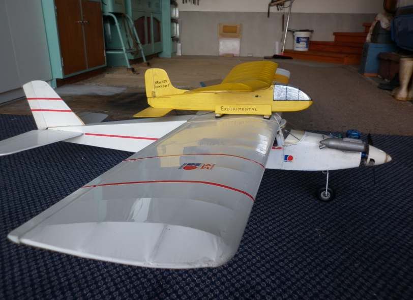
warps, wings level, and fin alignment. One or some of these will          seconds run increase to 4 seconds and repeat the analysis. Adjust as
      be out and need to be corrected.                                         necessary.
    o The slow check is a gentle push from your hand. We are looking
      to see a slow glide with slight right hand turn. This check is to        When you are increasing the motor run to 5 seconds increase the DT
      see the glide is “safe”. Add tail or nose weight, or move battery        delay to 2 seconds after motor cut. This will reduce the DT stresses on
      position, to achieve the glide. Do not be tempted to adjust              the wing.
      incidence.
    o If you make adjustments on either check then repeat the other            Safe Flights
      check again. Typically this will take a few iterations                   At this stage the model is safely climbing for 5 seconds and using the
                                                                               short DT. Our next objective is to take the power to almost full length
 • Set the timer. We need a very short flight with a quick DT. This is          run, transition safely and glide reasonably well.
   one of the most important ways to achieving safe initial flights. Set
   the motor run to 2 seconds and DT 1 second later. Anything longer           It is important to know the model will continue to accelerate through the
   than that is high risk.                                                     climb and the trim issues will change. As the model speed increases
                                                                               motor thrust changes have lessor effect and changes to rudder and
 • Ground run the systems and check that: you are comfortable                  wash-in have greater effect. Any incidence changes should be small
   holding the model, the motor cuts as expected and the DT works              and should go back to short motor run and quick DT (say 4 seconds
   consistently. Do this several times.                                        motor) before continuing on.

 • Practice the launch (without letting go). We are trying to launch the       Now the really scary flights are out of the way we can move onto
   model into its right hand spiral. The launch we want is just slightly       trimming for safe flights.
   right of wind, nose 45-60 degrees up and the right wing slightly
   down. Have a look at the photo. Bad launches are the cause of               Increase motor run to 7 seconds (still fast DT 2 seconds after motor
   many poor flights.                                                           cut). We continue to look for the safe right hand spiral climb. Issues that
                                                                               could start to appear:
Now you are ready for the first flight of the model. Take your time, be            • Model rolling to the left as speed increased – generally this is too
considered about what you do and watch carefully what the model                     much wash-in, if you can reduce wash-in make the adjustment,
does. With the short motor run and quick DT many potential problems                 otherwise small increase in right rudder tab
are able to be corrected before becoming fatal to the model.                     • Model climb flattening out, almost dropping nose. This is
Launch!                                                                             underelevation. Increase incidence slowly, as little as a 1/32
                                                                                    adjustment could be needed. Increasing elevation will cause the
Ok the first flight has occurred and one of number of things will have                model to roll right so watch for this and adjust rudder to
happened. Remember that in this phase we are seeking a right hand                   compensate
spiral climb, followed by a quick DT. Treat all re-flys as if they are first       • Model climbing safely but very flat. Generally this is either too
launches and analyse from there. Correcting one trim problem may                    much right rudder or too little elevation. This is a safe trim but not
show another.                                                                       optimal. Reduce right rudder first and if that is not enough look at
                                                                                    increasing elevation, again very small adjustments.
 • The model pulled strongly to the left starting to drop the nose.              • Model does fast right turns, without climbing much. This is difficult
   Either a poor launch or too much left thrust. If the model was safe              to pick but is often caused by overelevation. Extra incidence
   on the short run then fly it again to eliminate the bad launch option,            causes the model to roll right and hold pattern flat. Go back to short
   otherwise reduce left thrust and re-fly. If the pull to the left is slight        runs and reduce incidence very slowly.
   with the nose dropping then it will need more incidence. Increasing
   incidence will hold the nose up and roll the model to the right.            A number of these issues can look very similar and make it challenging
                                                                               to analyse. It is worth repeating “if at all possible have an experienced
 • The model pulled strongly to the right starting to drop the nose.           person with you”.
   Three things to consider here, poor launch, not enough left thrust,
   or not sufficient elevator. Again if model is safe on short run re-fly to      Once you are happy with the climb for 7 seconds it is time to
   eliminate the bad launch. If the launch is ok increase the incidence        concentrate on the transition. Part of the reason for 7 seconds is that a
   a wee bit (go back to the fast glide test to check) and re-fly. If that      9.5 second motor run should have sufficient height that it will be difficult
   did not correct it then increase the left thrust and re-fly                  to see the transition. At this stage I suggest a 7 second motor run and
                                                                               move to DT 5-10 seconds after motor stop. This is just enough to allow
 • The model corkscrewed to the left. Again check the launch – this            you to see the transition without the risk of a poor glide. What we are
   could be if you have launched left of the wind. Otherwise there is          looking for here is for the motor to cut and the model to smoothly
   probably too much wash-in; if you can reduce the wash-in then               transition to the glide. Be aware that any adjustments here will impact
   adjust this, otherwise add a small tab of right rudder (no more than        the climb trim. To transition well the model needs to be climbing right
   3/8inch (see photo) and re-fly                                               with sufficient speed to “flow” into the glide. The big issue here is that
                                                                               we do not want a stall at the end of the climb.
 • The model headed for a loop straight in front of you. Check the
   launch, this often happens if the launch is directly into or just left of   So to issues:
   the wind, even with a well-trimmed model. Otherwise reduce                   • Model climbs safely but very straight (probably high) and has little
   incidence slightly and re-fly. Reducing the incidence will also pull             or no transition. This is where the compromises come in. There is
   the model left so watch for this on the re-fly and if needed apply a             not have enough right turn to put the model into the glide. Add a
   little bit of right rudder. If the change in incidence is not sufficient          small bit of rudder and start at 4 second motor run and work back
   you may need to add downthrust to the motor.                                    up to 7 seconds motor run
                                                                                • Model climbs safely with a good spiral but the spiral reduces
 • The model climbed to the right but was dropping the right wing.                 towards the end of run and there is no transition. There is probably
   This is probably not enough wash-in. Add a small tab to the right               a wee bit too much wash-in, reduce wash-in if possible Less
   main wing. Re-fly.                                                               favored is more right rudder. Again back to 4 second run.
                                                                                • Model climbs safely with a good spiral but the model stalls on
 • The model headed off into right hand spiral climb…….well done!!                  motor cut and does not cleanly transition. This is starting to get into
   Enjoy.                                                                          tough trimming areas and probably the model does not have
                                                                                   enough speed to transition well. There are generally two ways to
When the initial flights are successful increase the motor run to 3                 fix this: increase elevation slightly (1/32 or less), this will increase
seconds and repeat the analysis. Any violent tendencies should have                roll to the right and is the right correction for slower models. Or
been eliminated by now and so you are looking for the same issues but              increase speed, on an electric model this really means increasing
smaller. Adjust as above. If the model pattern is safe use small                   propeller pitch. Increasing elevation is probably safer but there will
adjustments only and quietly trim the model. When you are happy off 3               be a cost in height. Increasing propeller pitch is riskier but could be
                                                                                   the right answer. Particularly for increasing propeller pitch revert to

June 2020                                                                                                                                        Page 7
the 4 second run and build up.                                            Generally changing tail tilt requires shimming at the front of the
     • Model climbs safely but is dropping right wing towards end of             tailplane mount, if you do this then put half the height of adjustment
       run. Transition is generally into a steepish dive. This is either         under the rear of the tailplane. Definitely go back to the short motor
       too little wash-in or too much right rudder. Start by adding a bit        runs and build up again.
       of wash-in (tab under right main wing), this generally has less
       effect than rudder and may be enough to hold the wing up. The              If the turn is too wide it is really a question of “can I Iive with this” or does
       alternative of reducing right rudder (could require adding left           it need fixing. A model with a wide glide will be pushed out of thermals
       rudder tab) needs to be addressed with small changes. Again               easier than one with a tighter turn. The adjustment, if needed, requires
       good practice to go back to 4 second run.                                 increasing the tail tilt. This also requires adjustment at the rear of
                                                                                 tailplane and building up from short motor runs.
    Be aware that adjustments made to fix the transition will probably
    effect the earlier part of the climb and that trimming may involve            If this is all good then let the model rip! Set the timer for 9.5 seconds
    the selection of compromises.                                                and see where it goes. Some issues may reappear and need fine
                                                                                 trimming but generally if you get to 7 seconds motor run you are pretty
    Ok the transition is good. Now is the time to check the glide.               safe.
    Increase the DT to activate 20-30 seconds after motor cut.
    Remember that for the initial flights you did the slow glide test, this       And after the safe flights there is so much more to learn, test and try.
    should mean that the glide is safe. If you have made significant              The model will be able to be fine trimmed. As your trimming confidence
    trim adjustments in the course of getting to here then repeat slow           improves you will see issues that can be addressed. There are
    glide test and use ballast to trim for safe glide. We want a slow            changes in props, different batteries, motors, connection leads and so
    glide with a definite right turn.                                             much more to be try.

    In adjusting the glide we use tail tilt for glide turn and slight cg         There are really good readings on trimming available with the best
    changes for glide speed. Changes to rudder and elevator are for              synopsis that I have seen being “Trimming that New Model” by Terry
    changing the power pattern.                                                  Thorkildson. This is available on FFoNZ facebook page
                                                                                 https://www.facebook.com/groups/1116574628384500/files
    Watch what the model is doing on glide. If it is flying nose down
    gradually increase the tail weight until the model either stalls or          Have fun and enjoy your E36. Even though this is written addressing
    mushes (i.e. sort of stops in glide and drops downwards) then take           competition, E 36’s will make very fine sports models. I look forward to
    a small amount of tail weight out and the glide should be good. If it        seeing you on the competition field and may the best person win!
    stalls add weight to the front of the model until stall disappears.
                                                                                 Thanks to Bernard S & Dave A for reviewing the drafts of these articles.
    If you have built the tail tilt in then the model should have some           Feel free to contact me to chat E36 with the best contact
    form of glide turn. The question is “is it too tight or too wide”            K.Barnes@xtra.co.nz

    If the turn is too tight there is no option other than to reduce tail tilt
    and open the glide up. If you do not almost certainly your model will
    spiral in from glide. Changing tail tilt also adjusts the incidence.

simple wing bags                                          Murray Irvine
Here’s an idea for you… I kept banging and denting my lovely new
wings and wanted some way to protect them. Hobbyking do a really
good cheap wing bag – but they never seem to be in stock. While                                                              When I saw the picture of
browsing in Kmart I discovered that they sell sponge-like yoga mats                                                          David Ackery launching in
(1700mm x 610mm x 3mm thick) for only $5. You can also get 5mm                                                               F1B on the cover of the March
thick versions for $8 each. It seemed too good an opportunity to miss. I                                                     2020 edition I thought I’d
bought two mats and cut them into a triangle shape. I used Ados F2 to                                                        come across a picture very
glue the edges together (I masked the edge with tape to stop the glue                                                        similar.
going into places I didn’t want it) – and even added a pocket for the
wing spar.

It works well – no more dumb dents – a simple, cheap, and effective
solution.

                                                                                  An almost identical photo taken
                                                                                  some 25 years earlier on page 100
                                                                                  of “The National Championships”
                                                                                  book written by John Malkin.

                                                                                  This is what makes David a top
                                                                                  competitor in the world of Free
                                                                                  Flight.

                                                                                  Even looks like the same field but
                                                                                  the trees have grown….

                                                                                  David Crook

Page 8                                                                                                                                  Model Flying World
DB
Nick Ward
Ghost Rider 50
Build log
The original Ghost Rider 38” design was published in 1968 as a
‘pocket-sized aerobatic model’ for use with Galloping Ghost RC
systems and .09cu.ins (1.5cc) motors. This was immediately
followed by the larger Ghost Rider 50, which was then modified
and re-published for 3-4 channel proportional radio control as a
follow on model from the Tyro Major basic trainer design using 5.Two panels initially butt-glued at
centre, taking care to make sure they
the same sized .19 to .25 cu.ins motors, and it is this design that I are properly aligned.
have used for my build.
The plan and set of wing ribs were purchased from DB Sport & Scale in 6.Cutting through wing sheeting to
the UK – I thoroughly recommend them if you wish to do a traditional instal dihedral brace before
reinforcing centre join with PVA-
build from a plan or a kit. They have a good range to choose from. The soaked glass cloth bandage. Note
older plan and build article is also available on the Outerzone website. cut-outs for mini-servos and wires.
I chose this model as my second electric scratch-build as I wanted a
fairly compact general purpose sport model for use at Kendall Park
which was relatively straightforward to fly, had good aerobatic
performance and which could use standard 2200mAH battery packs.
I’ve built and flown a Tyro Major glow model in the past which was a
terrific flyer, so Ghost Rider seemed to fit the bill.
1.DB always recommended making a
‘kit’ of parts before starting to speed
up construction. I had to cut a couple 7.Ailerons cut out and extra wood
of extra ribs as I was using wing- fitted for support – this took time to
mounted aileron servos, together carefully sand and get a good fit.
with LE and TE top and bottom
sheeting. Inboard ribs had to be
drilled for servo wires. Packing
pieces for LE and TE for use in
construction also had to be cut.
2.’Dry’ fitting ribs to sheet spar to
9. A typical David Boddington
check fit. Note cut-outs for wires and
construction method; fuselage sides
extra rib at servo mount position –
prepared with all doublers, gussets
strip aileron installation differs from
longerons and uprights pre-installed
plan
before sides go together. Note, I chose
to use thinner wood for sides, added
the longerons and changed the nose
structure to reflect the electric 8.Tailplane
installation. What look like engine built up
bearers are in fact battery pack rather than
supports. A triangular section corner all sheet
reinforcement is included for the original –
plywood engine mount former. Lite-ply hopefully a
gussets have been added for the wing bit lighter.
mount dowel holes.
3.Gluing ribs to spar over plan.
Gladwrap protects plan. Carefully
cut packing pieces supporting TE
cater for aligning symmetrical wing
section accurately over plan.
10.Gluing in formers to one fuselage
side at 90 degrees. Note built up
formers F2 &3, similar to Tyro Major
construction; plan formers actually
4. Sheet pieces on left assembled to
solid sheet. This change
make a light but very rigid wing
accommodates larger battery packs
panel on the right. Note paper tube
if necessary, and clear path for push-
glued in hole cut-outs to aid guiding
rods from servos.
servo wires during installation.
June 2020 Page 916.Hatch made up and spot glued in
position so fuselage sanding and
shaping can take place, rounding off all
corners for streamlining. U/C clamp
holes drilled and tested – good
opportunity to assemble model for
photo-opportunity!
11.It’s always nice part way through a
build to assemble the main components
to get a feel for the end result you are
aiming for – encouraging!
17.Airframe components prior to
covering; hatch is cut free, 1/32 ply added
to key points eg wing-band edges,
control horn mounts on built-up ailerons.
12.Pre-drilled F1 (6mm ply) holes for
cooling and motor mount. NB mount holes
1mm offset left of centre - F1 glued at slight
angles for down- and right-thrust.
18.Sig Koverall used, attached with dope,
13.Recycled 5/32” undercarriage wire from a Tower heat-shrunk then weave dope filled with 2-3
Hobbies ‘Uproar’ which was written off on only its second coats; exceptions are ailerons and elevator
flight – all salvageable parts were stripped from the where tissue doped on. Thinned acrylic paint
wreckage! applied after light sanding all over.
This was cut-down to lower it, and 3” lightweight foam
wheels added. Fastened with standard plastic clamps. 19.Fin glued carefully at 90 degrees
to tailplane using PVA – mating
surfaces pierced with mapping pin,
14.Cross grain sheeting of fuselage multiple holes created allow glue to
deeply penetrate wood fibres. Left
overnight.
Tail assembly glued to fus. using
24hour epoxy - gap-filling qualities
allow for any discrepancies
between mating surfaces eg fin to
fuselage. For this operation, wing
is seated in position so that
tailplane can be checked for
parallel alignment. Centreline
carefully marked to help accurately
position tail assy. Again left
overnight.
20.Control surfaces attached using
Dubro pinned hinges. Before covering, I
15.Internal structure drill 1/16” holes the hinge width apart in
– note extra gussets each of the mating surfaces and cut the
slot between them – this helps avoid
around F2 over splitting the wood any further than need
3mm ply U/C be. A sliver of material is removed to
mounting plate. allow for the hinge thickness. Once
covered, the slot is re-opened and the
hinges pushed into the control surface
first, secured by drilling a pair of 2mm
holes through the surface and hinge,
pegging in place with pieces of
toothpick. These are sanded flush and
glued in place with a dab of PVA or liquid
Cyano. The control surface is then
attached to the airframe by the same method (see photo). The pegs are then touched
up with paint to match the rest of the surface . This attachment method has proved
to be very strong and reliable on all my built-up models to date.
Page 10 Model Flying World21.Undercarriage clamped in place. 28.Servos mounted as far back as
possible to help achieve correct CG
over main spar position.
22.Simple wire tailskid epoxied to ply
underfin, protecting rudder.
28.Servos mounted as far back as
possible to help achieve correct CG
over main spar position.
23.Rudder and elevator control horns
attached. Corresponding pushrod exit
slots cut into fuselage side, taking care to
align correctly with horns.
30.Aileron servos and linkages
installed. Note Y-lead.
24.Battery/ESC mounting plate made up
and Velcro straps epoxied in place.
25.Testing battery/ESC fit
on mounting plate -
31.Receiver and spare battery pack
temporarily connected so control
surface function and throws can be
checked.
26.Rubber wing-seat strips epoxied to fuselage.
32.10x6 prop balanced and fitted – this
may change to 9x6 or 10x4 after initial
flight testing.
27.Airframe assembled with
battery/ESC/motor in place to
see where CG is – found to be
nose heavy at this point prior
to servo installation.
June 2020 Page 11I have often wondered if I could somehow utilize card tubes rather
than let them end up in the recycling bin.
The thinner ones (usually from toilet rolls or kitchen paper towels) are
too thin and easily torn up for our compost bins (worms love
cardboard!), but the ones found at the centre of baking paper or cling
wrap rolls are quite thick and therefore potentially of use elsewhere.
I started using this idea after designing/building my first bench
toolboard/caddy. I constructed a second, larger version for a more
extensive range of tools and materials. Different lengths of tube proved Card cap glued with PVA to
end of tube, weighted while
useful for cable-ties, epoxy mixing sticks, pens/pencils/markers etc. joint cures. Resulting tube is
stiff enough to be hung for a
variety of storage functions.
These tubes were considerably strengthened/stiffened just by glueing
one end shut with 1mm card, similar to that found on the back of writing
pads.
Tubes of any size, up to the length of the original, could be made up by
cutting down the original tube as desired before attaching the bottom
using PVA glue.
With the tube made up, they can then be attached to the wall/plywood
toolboard etc using a single screw near the top.
I have found them to be particularly useful for sorting out lengths of
spruce, piano wire, various stripped balsa sizes etc, and the great part
is that if they are mounted vertically on the wall of your shed, they take
up very little room that could be utilized for something else and you can
keep adding to them – I’ve already asked ‘wifey’ to put the thicker ones
aside rather than throw them into the recycling.
I hope others find this storage idea as useful as I am finding.
Page 12 Model Flying Worldfoam board fun David Goodall
Although I enjoy balsa construction, I have recently been focusing on
foam board construction due to its benefits of cheapness, lightness,
availability and ease and speed of construction. These aspects of the
material are a less daunting prospect for entry level aviation
enthusiasts. It is better suited to electric power and I have not seen
examples of glow versions probably due to fuel proofing issues. I
source foam board from a national large stationery supplier in 1 metre
by 0.8 metre sheets but there may be industrial suppliers that would
need a bulk order.
I scratch built a semi scale Pilatus PC6 which is ideal for foam
construction due to its mainly ‘boxy’ fuselage. The wing is also easy to
construct as it has no dihedral or taper. It is an easy flier due to its high
wing, and my two sons have flown it with a buddy radio. I followed on
with a second improved version, complete with camouflage. These model aircraft from a popular American kit maker. It helps to have plans
models that I am holding in the picture do not have undercarriage as and push out balsa parts! I managed to put my perfectionist tendencies
they are on loan to my sons models for flight testing. aside, and gave them complete freedom with the builds except for
technical advice and some minor assistance to my younger son. They
In an attempt to interest my two sons, aged twelve and nine, further into are holding the Typhoon and Mustang in the picture and they were
the hobby, I recently made a plane each for them of their request, a pleased with the end results.
Typhoon and an obscure German WWI biplane. In hindsight, these
are not the best for beginners, but a buddy radio system will help. The I have also experimented with ducted fan foam board jets and the
initial idea was that my sons would help with the builds, but a Nighthawk Delta in the picture just managed to fly. I made a smaller
combination of impracticalities of scratch building, young boys still version which flew too well, developed elevon flutter and crashed due
developing manual dexterity and my perfectionist tendencies, made to loss of orientation.
this plan fail. We compromised that I would build the airframes and
they would help install the electrics and programme the transmitter. For more information on foam board construction and designs, do a
The recent lockdown afforded plenty of time to complete both planes Youtube search for ‘Flitetest’. They have designed some incredible
as well as successful taxing on the front lawn, but they are yet to be test scale models, constructed exclusively from foam board and show how
flown due to lockdown restrictions. adaptable foam board can be. They also have some free plans on their
website. I have learnt a lot from them and their main goal is to inspire
Prior to this, what was more successful for the boys over the last people into the world of aviation. Maybe give it a try, even if just to test
Christmas holiday’s, was they each built a rubber powered balsa out a design.
PIGGY Piggy backing with model
aircraft is not a new thing, the fist
time I saw it was some years
BACK
Ian ago at the Nat's in Carterton. Its
Crosland just another way of getting a
Photos: glider up, especially one that
Alastair Rivers hasn't got ailerons. So two or
three years ago I built a little
yellow Hawker Head Butt and a
launching platform and fitted it
on to my old Hustler trainer
which caused a bit of excitement
at our Kapiti club. John Miller
decided to build a glider and
launcher which seems to work
better than mine. The secret is to allow a
reasonable gap between the two models wings
and a reliable release mechanism. In the glider you
can use either a separate servo or couple the the
elevator servo in the up position to work the
release. Test the release by applying a bit of up and
back hand pressure on the glider and it should slip
out of the catch easy. The other photos were taken
by Alastair at our last rally and is something for the
crowd to ooh' ah' about. The plane is my old Stol Mk
2 and Johns glider and launcher.
June 2020 Page 13A
Tiger
With
Only
One
Wing
Bruce
Pickering
“That’s not a Tiger Moth; it’s only got one wing!” I hear you say. But fear (This article originally appeared in
not, it truly is a Tiger Moth; let me explain. In July 1927, in an effort to Flight Lines Bulletin, of Hamilton
explore high speed flight, the deHavilland Company produced two MAC
small single-seat low wing monoplanes the\at they called DH71 Tiger
Moth. With its slender fuselage, designed to fit around the slim test pilot
Hubert Broad, this diminutive aeroplane had a wingspan of only 6.9 m
(22.5 ft). The top of the fuselage sides sloped outwards to
accommodate the pilot’s shoulders.
Powered by the 85hp ACD Cirrus engine, both aeroplanes were
entered for the King’s Cup Air Race, which at the time was the
accepted way of proving any new light aircraft. One was scratched
before the race; the other was withdrawn during the race due to
handling problems in the turbulent conditions. Soon after Hubert
Broad, in a modified aircraft that weighed only 411kg at take
off—wingspan was reduced to 5.7 m (18.7 ft), with a 135 hp Gipsy
engine—set a new altitude record of 5849 m (19,190 ft), having to give
up due to lack of oxygen, although the aircraft was still climbing at over
305 m (1000 ft) per minute!
In 1930 one DH71 was taken to Australia, where it crashed, killing the
pilot, due to engine failure on takeoff. The other airframe was
destroyed at Hatfield in 1940 during an air raid. So, although
successful, this experimental aircraft was short lived, which is possibly
why the name Tiger Moth was used again for the very well know
biplane of the 1930’s.
Following a conversation with a fellow club member, who suggested I
build a racing aeroplane, I dug up a picture of the dH71 in my research.
It satisfied my off-beat liking for the unusual and I knew I had to build
one. Further research unearthed a 3-view and some black and white
photos of the original aeroplanes.
Because the fuselage is long, I went for a scale of around 30%,
resulting in a wingspan of 84” (2134mm). Construction is
straightforward, the fuselage has slab sides, curved top and bottom,
with a full length “turtle deck” spine, starting just behind the
propeller—covering the engine—and extending to the fin. What made
it easier was that it has no separate canopy; just some windows each
side, which must have made visibility a nightmare for the pilot.
I built the wings by sliding ribs over front and rear spars, at scale
spacing. Between each pair of ribs there is a truncated rib back to the
front spar. The spars do not show, there is no sheeting, and the wing
looks exactly like the original. The flying and landing wires (fishing line
trace cable) are semi functional—I wanted to eliminate any possible
twist. The only tricky area was the engine cowl; the 3-view was
somewhat confusing and the black and white photos were a bit
obscure, so I applied some ‘artistic licence’ and the TLAR (That Looks
About Right) method. The upright mounted RCGF 30 motor fits snugly
inside the cowl.
Finding the right type of wheels at the required size—150mm—and
cost turned out to be a problem, so I decided to make my own. Initially I
considered turning them out of solid plywood, but that would be heavy.
So instead, I turned up a set of cone shaped plywood dies, male and
female. Then with five layers of veneer and glue placed between the
Page 14 Model Flying Worlddies it was simply a matter of closing the lot up in clamps. The
inside face of the wheel is flat, so ordinary ply was suitable.
Then I turned up a hub and rim to fit between the two faces
and glued the lot together. They turned out quite light and
strong. For tyres, I obtained some 20mm diameter round
foam sealing strip; when cut slightly undersized and glued
with CA they slipped onto the wheels nicely. The
undercarriage is bent up from 4.5mm piano wire, with fairings
shaped from litho plate and fixed on with silicone. To reduce
weight and drag deHavilland designed rubber bungee
springs inside the wheel hubs. This was too difficult for me to
copy so the model has no springs; however the large wheels
help to compensate for that.
I covered the fuselage with 24gm fibreglass cloth applied with
polyurethane varnish; the wings and tail are covered with
Koverall. Photos of the original were all black and white, but
documentation described the colour scheme for G-EBQU as
‘pale bronze and black, with tiger stripes on the flying
surfaces.’ I think I’ve got that pretty well right, except the
tapering tiger stripes are straight instead of wavy as on the
original.
The 30cc engine provides plenty of power and the aeroplane
lifts off smoothly. The first couple of flights were a bit twitchy,
indicating a need to move the centre of gravity forward. The
need for quite a bit of left aileron trim made me check the
wings and I discovered that the left wing’s incidence needed
to be reduced a small amount. With the CG moved forward it
was inclined to nose over on the ground, especially when the
grass was longer. To remedy that I moved the wheels forward
by 40mm—the only thing I deliberately did non scale. Now
ground handling is very good and she is very easy to fly—and
looks good in the air too. But now that we’ve moved to
Northland, my circumstances have changed and I have to
reduce the number of models in my hangar; so unfortunately,
she has to go.
home detention
Bernie Proctor
The first part of my "home detention' has been OK.
(apart from the best flying weather)
I have completed the Keilkraft BANDIT and now the
Carl Goldberg Sophisticated Lady. 2 meter span.
The lady is not as sophisticated as intended. The
flash canopy and pilot have been replaced with a
plain hatch and a Radian motor stuck on the front.
The 'T' tail has been lowered to cope with my dodgy
landings.
The coat of many colours is a result of using what I
had.
Fortunately I went into this lockdown with adequate
supplies, although glue is getting low.
I hope I'm still around to fly them.
June 2020 Page 15a
hobby
for
all
occasions
The Warners
It is two weeks into the general lockdown for most, as always, the
Warner family bucked the trend and arrived early. Due to a work trip to
Ireland the family lockdown began a week prior, so we were completely
unprepared and missed out buying way too much toilet paper.
Fortunately like most modelers we had many unfinished projects, so
the best thing to do was of course start something new! Being of sound
mind at the start of the lockdown had me thinking of the next Nationals
so we made a bit of a list
AGGY
This year Daniel and I are trying something different, thanks to the
Webby family we have got ourselves a reliable motor and have begun OUTDOOR AND INDOOR RUBBER SCALE
putting an aircraft around it (A Vic Smeed Popsie kitset from Belair Thanks to Ricky Bold and Stan Mauger’s guidance at the last Nat’s
Vintage kit cutters, it arrived while I was away). I also had a bit of a both Daniel and I have been bitten by the Rubber Bug. I have been
splurge and asked Ricky to pick me up something special when he was building the Easy Kit Mig3 and Daniel a Vintage Model Co Bird Dog that
in the UK, A Sam 35 Diesel that I am building a ¾ size 30 inch KK he won at the last nationals. Both of us are now at the covering phase
Ladybird for. All the parts were cut out in one day of scroll saw having had plenty of time to browse the internet for color schemes.
madness.
If you are looking for something to “have a go” at the next nats Indoor
and outdoor kit rubber models are a low cost to fun option, low stress
(once released) and plenty of tension... Rubber joke
All the info you need including kit scale rules and contacts can be found
on the Model flying Site
https://www.modelflyingnz.org/sigs/ff_cl_scale.html
There are heaps of kitset options available out there
FPV
And to keep the reflex’s sharp we have setup the lounge as an indoor
racetrack for the quad, none of us have mastered the FPV goggles yet
but there are a few weeks to go. Josh has shown the most promise with
the right amount of youth and reflexes. Probably helps that he didn’t
pay for the quad, house, TV or other obstacles.
We are so lucky to have a hobby that can be enjoyed no matter what
the circumstances are, I have spent more hours building and tinkering
than flying but am still getting a buzz.
Test runs in the garden had the bonus of making the laundry smell just
like we had been at the flying field. Ta k e c a r e o f
I have just finished a 2.4 Ghz yourselves and the
Radio dethermalizer, the brains of others around you
the unit can be bought from Phil and stay safe, I look
Green......................................... forward to seeing
http://www.peterboroughmfc.org/ what you have all
technical- articles2016/1-R- come up with once
DT.htm. This will allow me to bring we get the OK to
the models down during test runs venture back outside.
and keep within our flying site
boundary.
The rest of the stuff was found in
the third draw of my bench.
F3J
Replaced the sellotape servo
covers with something a bit more
modern (shame I now must wait
for Bunnings to reopen before I
can buy some matching spray-
paint). I also had the chance to
load the new model setup into my
radio, something I should have
done a long time ago. All the soaring fleet have had a thorough going
over to be ready for our eventual release. Batteries have been
discharged and checked and put into safe storage and the internet
trawled for potential Birthday and Xmas goodies.
Page 16 Model Flying Worldapart from each other so that load-induced voltage sag does not trigger
the switch-over to the reserve supply. The spread also helps with
setting up alarms on your radio as well. A 1V spread is what I have
chosen and seems to work well.
Since your primary power supply is likely already fixed or decided, the
only thing left to decide is how to provide the backup power source. You
must consider the forward voltage-drop introduced by the diode (allow
0.5V as your initial consideration). You will also need to consider the
discharge curve from a battery.
Let’s look at a few options for backup power supply:
• 1S LiPo only – Simple but is there enough voltage with the voltage
drop and a 50% battery? 3.7 Vs – 0.1 = 3.1 Volts. This might not be
enough…
• 2S LiFe only – Simple plenty of voltage but you will need HV servos
• 2S LiPo only – Simple but its most likely the same voltage (or
higher) as your primary supply, so unless you drop it down by
adding several diodes, this is perhaps not the best choice.
• 1S LiPo with a 5V regulator. Adds complexity but you get 5 volts
consistently. Combine this with a low forward drop diode and you
have a workable solution for LV servos.
I promised Rowdy a write-up for the MFNZ Flyers World Diodes
magazine, and while we are all in a pandemic lock-down, I may as The diodes you want are Schottky diodes for their low forward-voltage
well get it done. Please go easy, this is my first at such a venture. drop. All diodes will have a specified forward voltage drop, and in
This is more a build and test log of someone else’s idea. I can’t simple terms is a guide to how much voltage you lose when applying
take credit, but I will share my experiences and thoughts. current through it. Less is better obviously. Here are some diodes
Here is a link to the original article on rcgroups: people have used successfully in this application:
https://www.rcgroups.com/forums/showthread.php?2404539-A-low- • SB540 40V 5amp. You will need
cost-battery-backup-system two of these, joining the two
cathodes. This is what I have used.
So, what is it and what is it for? It is an independently powered and https://www.digikey.com/products/
automatic fail-over redundant RX power system, for when your en?keywords=sb540fsct-nd
primary power source fails. If your primary power source fails, it will • FYPF1545DNTU 40V 15amp –
continue powering the model for a safe return home. It is intended for this is a dual diode package. You
use in electric launched RC sailplanes like a Maxa or a Radian, will only need one of these. The
although it could work with most electric powered fixed-wing models centre pin is the common cathode.
with appropriate care and thought. The outer pins are the primary and
secondary power sources.
The need for such a device became apparent to me after a well-known • Smart Bypass Diode. These
brand of altitude limiting switches had some manufacturing issues with effectively do the same job as the
faulty servo plug pin crimping. Given the altitude limiter is normally the simpler diodes above but with
conduit of the main power to the model, I felt people could have easily “zero” forward voltage drop. They
lost their models, and we did lose some to unknown power related are a bit more expensive and a little
reasons about that time. A device like this may have saved them. harder to wire up. You would need
two of these....................................
h t t p s : / / n z . m o u s e r . c o m / P r o d u c t D e t a i l / Te x a s -
Instruments/SM74611KTTR?qs=KLh5H0KA3CMOyzy9HDzES
A%3D%3D
My Build
This is a picture of one of my devices I built with two SB540 diodes and
a 5V 2amp regulator. A single cell 400 mAh LiPo powers the 5V
regulator (red board on the left) and plugs into a standard JST
connector. On the right is the primary power source and output. The
orange is the ESC signal wire and is passed-through. Just to the right
of the regulator are the two diodes one (below) powered by the output
of the regulator, the other (above it) is powered from the BEC. The two
cathodes are joined and that powers the RX. All wrapped up in heat
shrink! It’s nice and small and a 1S LiPo is easy to stow in today’s slim
This diagram shows a representative circuit. D1 and D2 are Schottky
F5J fuselages.
diodes. In this diagram the RX will always receive the highest of the
two source voltages. If the 8.4V power source should fail, the receiver
will continue to be powered by the 4.2V source. If either source of
power is interrupted, the RX always get power from the other.
Simplicity is key here. The more complex a system is the more points
that can fail. Some people will apply this to thinking that the presence of
a redundancy system is added complexity and increases the overall
likelihood of the complete system to fail. I subscribe to the thinking that
any redundant system is highly likely to be better than none, especially
so if it is simple.
I program my Castle BEC to output 6V. My backup supply is a 400 mAh
Typically, we would have the primary power supply from a LiPo or BEC LiPo powering a 5V regulator minus the ~0.3V forward drop. which will
as we would normally have it, and a reserve battery pack to provide the give me a stable 4.7V supply for at least 10mins. This should be
redundant power supply. For the behavior of the circuit to be enough power and time to come home immediately and land safely. I
predictable, we need to ensure the two source voltages are far enough could use a zero-drop smart-diode, but 4.7 volts is plenty in my book.
June 2020 Page 17Parts: my backup voltage is 5.0 volts. I set an alarm on the radio when the
• 5V 2amp regulator. telemetry RX voltage drops below 5.1 Volts (this allows for a 0.9V sag
http://www.ebay.com/itm/DC- under load). This way I am alerted if the primary power supply fails, and
DC-Boost-Voltage-Converter-4- I have switched over to backup power. Once this happens, it would be
2V-5V-9V-12V-2A-Mini-Step- prudent to return home and land immediately.
Up-Power-Supply-Module-
/122167130715 Operation
• 2 x SB540 schottky diodes. At the field my usual operational procedure is to:
https://www.digikey.com/produc 1. Charge/check the backup 1S LiPo
ts/en?keywords=sb540fsct-nd 2. Power-up radio and select model
• Plugs and wires 3. Plug in the backup power system. Verify the model is working on
backup power and my alarm on the radio is sounding
Wiring up 4. Plug in the main LiPo to power the model. Verify it’s all still running,
This shows how I have wired mine up relative to the usual and the alarm has stopped
components. In my case I have put the ALES limiter before the 5. Good to go and fly
redundant power supply system. This way if my primary power supply 6. Unplug both power supplies (order doesn’t matter)
fails, the ALES limiter will turn off. F5J heights
will still be stored in the unit, so there isn’t a Testing
problem there. You could put it on the other My main concern with my setup is the 2amp regulator on the backup
side, but I feel it’s introducing more points of side. I worried that dropping full flaps at speed could see the current
failure after the redundant system increasing draw exceed 2amps. So, I’ve done a bit of bench-testing to verify the
chances of total power failure. stated 2amp rating. I tested with several large resistors in series to load
up the regulator while measuring the current flow. I can verify the
regulator can run a full 10mins on an average of 2.1amps. I did a torture
test of 5.1 amps for a full minute. The regulator got extremely hot and
started smelling like BBQed circuit smell, but it held a full minute at
5amps without dying.
From doing the test, I have learnt:
1. 2amp rating is conservative, and the device should be suitable for
emergency only come-home-now power.
2. Heat dissipation is the most critical. My tests were done with the
regulator exposed to open air. In practice the unit will be wrapped in
heat-shrink, so my numbers may be slightly better than real-world,
but easily within expected loads.
Alternatives 3. Flaps popping down while on the backup regulated supply
Using the smart-diode and an shouldn’t be a big issue if you’re sensible about it – e.g. gradual
deployment while going slow on final.
Page 18 Model Flying WorldYou can also read