Learn-/Training Document - Siemens
←
→
Page content transcription
If your browser does not render page correctly, please read the page content below
Learn-/Training Document | PA Module P02-01, Edition 02/2020 | Digital Industries, FA

                                                 Learn-/Training Document
                                                 Siemens Automation Cooperates with Education
                                                 (SCE) | As of Version V9 SP1

                                                 PA Module P02-01
                                                 SIMATIC PCS 7 – HMI generation

                                                                                                   siemens.com/sce

For unrestricted use in educational / R&D institutions. © Siemens 2020. All rights reserved.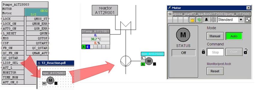
Learn-/Training Document | PA Module P02-01, Edition 02/2020 | Digital Industries, FA Matching SCE Trainer Packages for this Learn-/Training Document • SIMATIC PCS 7 Software Package V9.0 (set of 3) Order No.: 6ES7650-0XX58-0YS5 • SIMATIC PCS 7 Software Package V9.0 (set of 6) Order No.: 6ES7650-0XX58-2YS5 • SIMATIC PCS 7 Software Upgrade Packages (set of 3) Order No.: 6ES7650-0XX58-0YE5 (V8.x V9.0) • SIMIT Simulation Platform with Dongle V10 (contains SIMIT S & CTE, FLOWNET, CONTEC libraries) – 2500 simulation tags Order No.: 6DL8913-0AK00-0AS5 • Upgrade SIMIT Simulation Platform V10 (contains SIMIT S & CTE, FLOWNET, CONTEC libraries) from V8.x/V9.x Order No.: 6DL8913-0AK00-0AS6 • Demo Version SIMIT Simulation Platform V10 Download • SIMATIC PCS 7 AS RTX Box (PROFIBUS) only in combination with ET 200M for RTX – Order No.: 6ES7654-0UE23-0XS1 • ET 200M for RTX Box (PROFIBUS) only in combination with PCS 7 AS RTX Box – Order No.: 6ES7153-2BA10-4AB1 Note that these trainer packages are replaced with successor packages when necessary. An overview of the currently available SCE packages is available at: siemens.com/sce/tp Continued training For regional Siemens SCE continued training, get in touch with your regional SCE contact siemens.com/sce/contact Additional information regarding SCE siemens.com/sce Information regarding use The SCE Learn-/Training Document for the integrated automation solution Totally Integrated Automation (TIA) was prepared for the program "Siemens Automation Cooperates with Education (SCE)" specifically for training purposes for public educational facilities and R&D institutions. Siemens does not guarantee the contents. This document is to be used only for initial training on Siemens products/systems, which means it can be copied in whole or part and given to those being trained for use within the scope of their training. Circulation or copying this Learn-/Training Document and sharing its content is permitted within public training and advanced training facilities for training purposes. Exceptions require written consent from the Siemens. Send all related requests to scesupportfinder.i-ia@siemens.com. Offenders will be held liable. All rights including translation are reserved, particularly if a patent is granted or a utility model or design is registered. Use for industrial customer courses is explicitly not permitted. We do not consent to commercial use of the Learn-/Training Document. For unrestricted use in educational / R&D institutions. © Siemens 2020. All rights reserved. 2 p02-01-hmi-generation-v9-tud-0719-en.docx
Learn-/Training Document | PA Module P02-01, Edition 02/2020 | Digital Industries, FA

We wish to thank the TU Dresden, particularly Prof. Dr.-Ing. Leon Urbas and the Michael Dziallas
Engineering Corporation and all other involved persons for their support during the preparation of this
Learn-/Training Document.

For unrestricted use in educational / R&D institutions. © Siemens 2020. All rights reserved.                          3
p02-01-hmi-generation-v9-tud-0719-en.docx
Learn-/Training Document | PA Module P02-01, Edition 02/2020 | Digital Industries, FA

Table of contents
1     Goal ................................................................................................................................................. 5

2     Prerequisite...................................................................................................................................... 5

3     Required hardware and software ...................................................................................................... 6

4     Theory ............................................................................................................................................. 7

    4.1      Theory in brief ..........................................................................................................................7
    4.2      Objectives of process control ....................................................................................................8
    4.3      Concepts of representation .......................................................................................................8
    4.4      Representation techniques ..................................................................................................... 10
    4.5      HMI generation in PCS 7 ........................................................................................................ 13
    4.6      References ............................................................................................................................. 14
5     Task ............................................................................................................................................... 15

6     Planning......................................................................................................................................... 15

7     Learning objective .......................................................................................................................... 15

8     Structured step-by-step instructions................................................................................................ 16

    8.1      Faceplates in the plant hierarchy ............................................................................................ 16

    8.2      Creating block icons ............................................................................................................... 19

    8.3      Compiling and downloading objects ........................................................................................ 22

    8.4      Configuring WinCC ................................................................................................................. 27

    8.5      Editing the faceplate for the multipurpose plant ....................................................................... 37

    8.6      Configuring the picture change ............................................................................................... 44

    8.7      Editing the faceplate for T1_educt_tanks ................................................................................ 49

    8.8      Linking of picture elements with PLC tags ............................................................................... 55

    8.9      Saving in the project library ..................................................................................................... 59

    8.10     Adapting the orientation of the faceplates................................................................................ 61

    8.11     Testing the faceplates............................................................................................................. 67

    8.12     Checklist – step-by-step instruction ......................................................................................... 76

9     Exercises ....................................................................................................................................... 77

    9.1      Tasks ..................................................................................................................................... 77

    9.2      Checklist – exercise ................................................................................................................ 80

10    Additional information ..................................................................................................................... 81

For unrestricted use in educational / R&D institutions. © Siemens 2020. All rights reserved.                                                                     4
p02-01-hmi-generation-v9-tud-0719-en.docx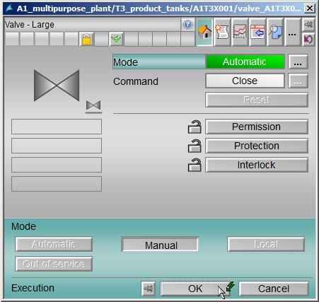
Learn-/Training Document | PA Module P02-01, Edition 02/2020 | Digital Industries, FA

HMI generation
1          Goal
           After working through this module, the students can design and implement a graphical user
           interface for efficient process control. They will also become familiar with the objectives of
           process control. They understand the basic concepts of representation and various
           representation techniques. This will enable the students to generate a usable and effective
           graphical user interface in PSC 7.

2          Prerequisite
           This chapter builds on chapter 'Functional safety'. To implement this chapter, you can use an
           existing project from the previous chapter or the archived project 'p01-08-exercise-r1905-en.zip'
           provided by SCE. The download of the project(s) is stored on the SCE Internet for the respective
           module.

           The (optional) simulation for the SIMIT program can be retrieved from the file 'p01-04-plantsim-
           v10-r1905-en.simarc'. It can be run in demo mode.

For unrestricted use in educational / R&D institutions. © Siemens 2020. All rights reserved.                          5
p02-01-hmi-generation-v9-tud-0719-en.docx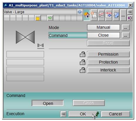
Learn-/Training Document | PA Module P02-01, Edition 02/2020 | Digital Industries, FA
3 Required hardware and software
1 Engineering station: Requirements include hardware and operating system
(for further information, see Readme on the PCS 7 installation DVD)
2 SIMATIC PCS 7 software V9 SP1 or higher
Installed program packages (contained in SIMATIC PCS 7 Software Trainer
Package):
Engineering PCS 7 Engineering
Engineering BATCH Engineering
Runtime Single Station OS Single Station
Runtime Single Station BATCH Single Station
Options SIMATIC Logon
Options S7-PLCSIM V5.4 SP8
3 Demo Version SIMIT Simulation Platform V10
2 SIMATIC PCS 7
V9 SP1 or higher
1 Engineering Station
3 SIMIT V10 or higher
For unrestricted use in educational / R&D institutions. © Siemens 2020. All rights reserved. 6
p02-01-hmi-generation-v9-tud-0719-en.docx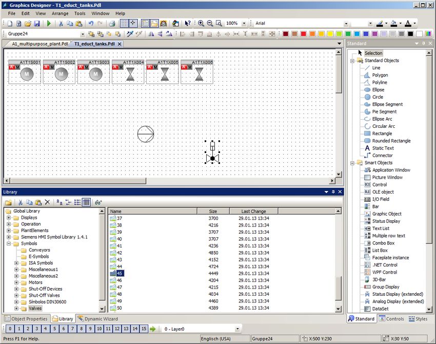
Learn-/Training Document | PA Module P02-01, Edition 02/2020 | Digital Industries, FA

4          Theory
4.1        Theory in brief
           A modern process control system such as PCS 7 provides operating personnel various screen-
           based windows to the process via which all process control tasks can be completed. Due to the
           large amount of information from the technical process that the operator must take in and
           process, it is useful to structure the information. In addition, certain rules for navigation and
           representation must be adhered in order to produce an easy-to-operate interface to the technical
           process that effectively supports operators in carrying out their various process control tasks.

           PCS 7 supports the design process of process pictures for operator control and monitoring in
           multiple ways. First, for many of the elementary blocks and individual control functions used in
           basic automation, operating icons and operator panels are defined that enable project-wide
           uniform interaction with similar technical equipment. Second, the plant hierarchy can be used to
           conveniently structure the information display.

           This structure allows a large number of elements of the operating system that would have to be
           implemented manually in other systems to be generated automatically and error-free in a single
           generation run. Two essential tasks remain for designing process pictures. The first is the
           representing of static process structures (tanks, pipes, etc.) for better orientation. The second is
           the inserting of elements for navigation along process streams on a plant hierarchy level.

           Figure 1: From the individual drive function to the faceplate

           The generation run creates block icons for all operable blocks of a hierarchical level. These icons
           then only have to be positioned and enhanced with static elements in order to obtain a complete
           faceplate (see Figure 1).

For unrestricted use in educational / R&D institutions. © Siemens 2020. All rights reserved.                          7
p02-01-hmi-generation-v9-tud-0719-en.docx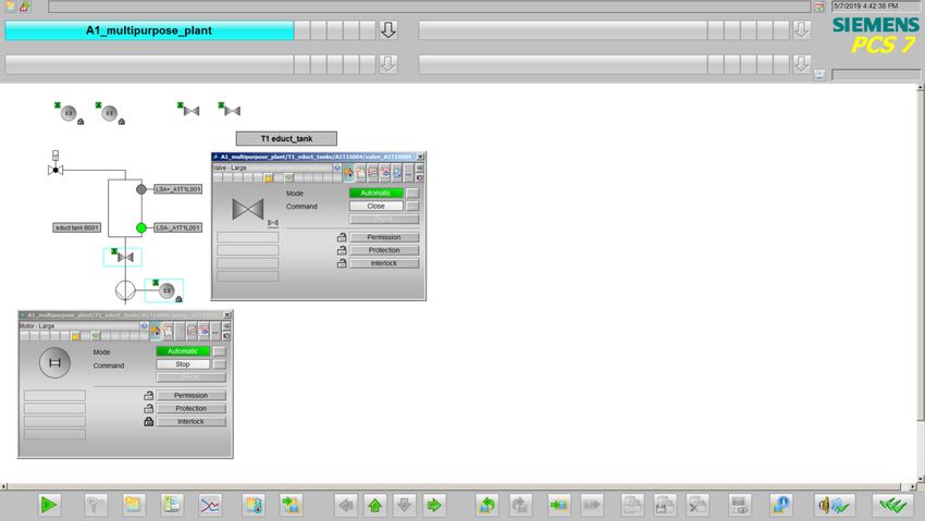
Learn-/Training Document | PA Module P02-01, Edition 02/2020 | Digital Industries, FA

4.2        Objectives of process control
           The task of an operator in a process plant is to operate this plant for the intended purpose in an
           economical and environmentally compatible manner. This task is called process control. They
           must ensure a consistently high product quality and amount (yield) and keep the amount of waste
           as low as possible, while at the same time compensating for disturbance factors such as varying
           properties of raw material, plant malfunctions or fluctuating throughput. The operator must see to
           it that the availability and service life of the plant is maximized. Furthermore, the operator must
           ensure that emission limits are observed and energy and material consumption is minimized [1].

           To attain these goals, an operator must always be able to monitor the plant, diagnose problems
           and intervene in the running process to solve them. An operator station in the control room
           serves as the operator's work station. This operator station has all the displays and possibilities
           of intervention that an operator needs to perform his work. The control system provides the
           operator a user interface that he can use to carry out his tasks according to his abilities, skills and
           requirements [1].

4.3        Concepts of representation
           The representation of data and information on the graphical user interface has a decisive
           influence on the performance of the operator. For this reason, it has to be matched to the
           operator's abilities, skills and requirements. The following questions must therefore be answered
           in turn:

           4. For whom and for what purpose does the representation serve?

           5. What is to be represented?

           6. How is it to be represented?

           These questions depend on the plant that is being planned and, therefore, have to be answered
           for the respective project. However, the following aspects always have to be considered:

           Organization of the information and data to be represented

           The information and data to be represented has to be organized suitably for the representation.
           For this, it is necessary to specify how the existing elements are structured and arranged, how
           they relate to each other and how the representations can be navigated between. Accordingly,
           the total amount of information and data to be represented must be specified (quantitative
           aspect). And, the information and data that is to be visualized simultaneously and together must
           be specified (qualitative aspect).

For unrestricted use in educational / R&D institutions. © Siemens 2020. All rights reserved.                          8
p02-01-hmi-generation-v9-tud-0719-en.docx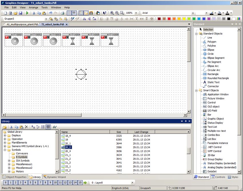
Learn-/Training Document | PA Module P02-01, Edition 02/2020 | Digital Industries, FA

           Here, the ratio of what is new (information, dynamic picture components) to what is known (data,
           static picture components) must be decided. The aim is the maximize the proportion of
           information but to provide enough data to allow accurate and appropriate interpretation of the
           information.

           The result is a distribution of information and data among the various faceplates. How the
           operator goes from one faceplate to another must then also be defined (navigation).

           Density

           Depending on the user interface, only a limited area is available for simultaneous representation
           of data and information. To ensure that the information and data remains legible and
           distinguishable in all operating situations, only a certain percentage of this area is to be occupied
           with characters. This percentage is referred to as the density of the representation.

           The recommended density depends on the type of characters and display elements as well as on
           the necessary structuring of these elements. Thus, it depends on the representation technique
           used. For example, the density of a process flow diagram should be no more than 50%; for a
           message page, on the other hand, it may be up to 80% [1].

           Coding

           Coding is used to specify how certain information is represented. Information can be coded by
           color, shape, form, extension, direction (angle), position and dynamics (flashing). A uniform
           coding facilitates the intake and evaluation of information by the operator.

           An effective coding is characterized by the fact that it is clear, distinguishable and consistent with
           existing conventions. That is why the color green should never be used for a STOP signal. If, for
           example, a red flashing signal is used instead as a coding for STOP, this coding should be used
           consistently for the entire user interface. Also, it is necessary to avoid reuse of this coding for
           other information in order to rule out confusion. In addition, an effective coding should be obvious
           so that it is easy to learn and remember for the operator.

           Conspicuousness

           A central function of the user interface is to direct the operator’s attention to important
           information. Because a faceplate generally displays a variety of information, it is advisable to
           design this information with varying conspicuousness corresponding to its relevance and priority.
           The more conspicuous the information is represented, the sooner it will be spotted. In addition,
           the operator can recognize the information that requires the most attention at the moment based
           on its conspicuousness. Table 1 shows the stepping up of conspicuousness using a few
           examples.

For unrestricted use in educational / R&D institutions. © Siemens 2020. All rights reserved.                          9
p02-01-hmi-generation-v9-tud-0719-en.docx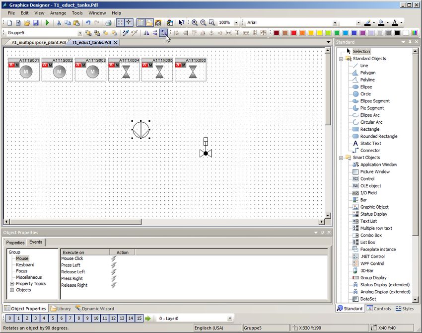
Learn-/Training Document | PA Module P02-01, Edition 02/2020 | Digital Industries, FA

                                                                        Increasing conspicuousness of
                                                                      means

                      Increasing conspicuousness of visualization     Mittel Combination of means                             Application
                                                                                               Acoustical
                                                                     Contrast Color Flashing
                                                                                                 signal
                                                                        high        X         X          X        Alarm

                                                                                                                  Change of state (requiring
                                                                        high        X         X           -
                                                                                                                  acknowledgement)
                                                                                                                  Change of state (not requiring
                                                                        high        X         -           -
                                                                                                                  acknowledgement)
                                                                        high        X         -           -       Curves
                                                                                                                  Text of message line, explanatory
                                                                        high        -         -           -
                                                                                                                  texts
                                                                                                                  selctable and operator-controllable
                                                                      medium        -         -           -
                                                                                                                  object (keys)
                                                                                                                  currently not selctable and operator-
                                                                        low         -         -           -
                                                                                                                  controllable object

           Table 1: Application of stepped conspicuousness according to [1]

           Consistency

           Often, a particular piece of information appears in several representations at the same time. In
           this case it is important that this information be represented consistently throughout the user
           interface. This means the information has the identical appearance in all representations and
           behaves identically. The same terms and symbols must always be used. The operating sequence
           should always be the same. Likewise, it is recommended that the timing and content of the
           system response to operator inputs be similar.

4.4        Representation techniques
           Basic structure of the display area

           The display area should always be structured the same for all representation modes. This
           facilitates the orientation, information intake and, thus, process control for operator. The basic
           structure recommended for this according to VDI 3699 [1] is shown in Figure 2. A message line in
           which the latest messages are displayed as group messages is located at the top. Below it is an
           overview field in which the available representations (for example, process pictures in PCS 7)
           are listed. There is the option to open any representation from here. The working area occupies
           the largest part of the display area. The currently selected visualization is displayed here.

For unrestricted use in educational / R&D institutions. © Siemens 2020. All rights reserved.                                                                10
p02-01-hmi-generation-v9-tud-0719-en.docx
Learn-/Training Document | PA Module P02-01, Edition 02/2020 | Digital Industries, FA
The bottom area contains the key field for activating general functions. In the working area,
windows with supplementary information (such as different views of PCS 7 blocks) can be
opened in addition. All areas except the working area are reserved and are always displayed.
Message line Overview field
Display window Working area
Key field
Figure 2: Basic structure of a display area
For unrestricted use in educational / R&D institutions. © Siemens 2020. All rights reserved. 11
p02-01-hmi-generation-v9-tud-0719-en.docxLearn-/Training Document | PA Module P02-01, Edition 02/2020 | Digital Industries, FA
Flow diagrams
A flow diagram is a "schematic representation of components including their connection through
(flow) lines to show relationships in a control plant and in control engineering" [1]. It represents
the plant structure in a simplified manner and provides information about the paths of material,
energy and signal flows between the different plant units. With the aid of flow diagrams, process-
and control-related information is represented and interventions in the process are made
possible.
Flow diagrams consist of static and dynamic elements. The static picture elements are
represented by the root screen. This root screen contains the dynamic picture elements that
are continuously updated.
The static root screen provides the context for the dynamic picture elements, which means it
indicates the meaning of the represented objects and their relationship to each other. The root
screen represents all data that remains unchanged during the display. It contains, for example,
the picture background, the headings and labels as well as the plant units and the devices (if their
representation is not supposed to change).
The dynamic picture elements provide the information for process control. Display elements
display changes, time variations and relationships of the process values. Thus, they reflect the
state of the plant, control system or process. Selection and operator control elements
allow the operator to perform operator interventions for process control. In addition, there is often
the option to display additional information such as function diagrams or trends in the flow
diagram as a window.
Flow diagrams are subdivided as follows:
– Control flow diagrams represent only components of the control system such as loop
controllers, actuators and controllers as symbols. They are connected to each other with
signal flow lines.
– Process flow diagrams graphically represent plant units in a simplified way using
symbols. Here, three different kinds are differentiated:
– A basic flow diagram represents plants, plant sections or plant units in the form of
rectangles. They are connected to each other with flow lines for materials, energy or
energy sources.
– A process flow diagram represents processes using (simplified) graphic symbols.
The symbols represent the corresponding plant units and are connected to each other
with flow lines.
– A piping & instrumentation flow diagram (P&I diagram) represents the technical
equipment of the plant using graphic symbols. In addition, process tags, control blocks
and actuators are represented. The symbols are connected to each other by lines for
pipes and signal paths.
For unrestricted use in educational / R&D institutions. © Siemens 2020. All rights reserved. 12
p02-01-hmi-generation-v9-tud-0719-en.docxLearn-/Training Document | PA Module P02-01, Edition 02/2020 | Digital Industries, FA
In PCS 7, flow diagrams are referred to as process pictures. Various process pictures will be
created for the configured plant within the scope of the step-by-step instructions.
4.5 HMI generation in PCS 7
PCS 7 has an extensive operator control and monitoring system that consists of the following
subsystems [2]:
– A graphic system for displaying process information and for operator process control.
– A curve system for representation and analysis of time series of stored process values.
– A message system for diagnosing the process.
– A log system for documenting the process.
– An archive system for storing and keeping process values, messages and logs.
In this chapter, the graphic system of PCS 7 is introduced. The alarm system will be described in
the subsequent chapter 'Alarm Engineering'.
The graphic system represents the plant in a plant overview. It displays process pictures in the
working area of the user interface, provides elements for operator process and system control
and indicates alarm states. The corresponding user interface is generated on the operator station
(OS) of the system. The OS is thus the central station for operator control and monitoring of a
PCS 7 plant [2].
Configuration of the user interface in PCS 7
The selected plant hierarchy of the project is the basis for the organization of the user interface.
The created plants and subunits are represented in the user interface through corresponding
process pictures. Picture names and directory names of the plant hierarchy are applied
automatically. In process mode, the available process pictures are represented in the overview
area corresponding to the plant hierarchy.
The process pictures of a project are first created at the corresponding location in the plant
hierarchy and assigned to an OS. The OS is then compiled. The process pictures can then be
configured in the Graphics Designer of the WinCC Explorer. The Graphics Designer is
an editor where static and dynamic picture elements can be inserted, arranged and
interconnected.
For unrestricted use in educational / R&D institutions. © Siemens 2020. All rights reserved. 13
p02-01-hmi-generation-v9-tud-0719-en.docxLearn-/Training Document | PA Module P02-01, Edition 02/2020 | Digital Industries, FA
Configuration of the process pictures in PCS 7
Operator control and monitoring-capable technological blocks from PCS 7 libraries already have
corresponding graphic representations, so-called block icons. When the process pictures are
configured, the block icons are inserted automatically in the corresponding picture. Block icons
represent the most important information about the represented block as an overview in the
process picture.
Various pre-configured faceplates can be opened as a window in the working area via the block
icons. Faceplates are dynamic picture elements that are connected to the parameters of the
represented block and are updated automatically. They allow extensive operator control and
monitoring of the associated technological block for the operator. Depending on the block type,
different views exist for the associated faceplates. These views enable access to parameters for
very specific tasks. For example, in addition to the standard view there often also is a parameter
view for assigning parameters, an alarm view for diagnostics or a limit view for setting operational
limits of the setpoint. The views offered depend on the represented technological block.
The Graphics Designer provides additional dynamic standard objects and inserts them
manually. These objects can be interconnected directly with the I/Os of the blocks in the CFCs
and SFCs and thus realize the desired dynamic behavior. Examples of standard objects are input
and output fields for entering and displaying values, status indicators for displaying binary states
of an object as well as bars for the relative representation of values.
In addition, the Graphics Designer provides various libraries with pre-assembled graphic
elements such as pipes or valves that can be used to create the static root screen. Alternatively,
there is the option to also create and use your own graphics.
In the step-by-step instructions below, additional characteristics and capabilities of the Graphics
Designer will be presented. Several other important WinCC tools are also presented.
4.6 References
[1] VDI 3699 (Edition 2014-01): Process control using display screens.
[2] SIEMENS (2017-10): Process Control System PCS 7: OS Process Control (V9.0 SP1).
A5E39221482-AB. (support.industry.siemens.com/cs/ww/en/view/109754981)
For unrestricted use in educational / R&D institutions. © Siemens 2020. All rights reserved. 14
p02-01-hmi-generation-v9-tud-0719-en.docxLearn-/Training Document | PA Module P02-01, Edition 02/2020 | Digital Industries, FA
5 Task
In this task, a few presets are made in SIMATIC Manager followed by creation of the operator
station (OS).
An overview picture of the multi-purpose plant and one-unit picture each for the educt tank,
reactor and product tank are to be created. A solution for a tank for each plant unit will be created
first.
6 Planning
To start, the target system on which the OS is to run must be defined. In these instructions, this is
the same computer on which the engineering is performed. But it does not have to be. The
following specification will be made:
– Type of network connection: TCP/IP
– Network connection used: PLCSIM.TCPIP.1
– Number of monitors: 1
– Resolution of monitors: 1920x1080
The CFCs and SFCs created previously in the preceding projects are a basis for overview and
unit pictures. Once these are automatically generated by PCS 7, they only have to be arranged
on the faceplates.
The static elements that are created when implementing these instructions are another basis.
Because several very similar plant units exist, it makes sense to use the project library of WinCC
and to simplify the engineering in this way. This will be demonstrated using the example of an
educt tank.
7 Learning objective
In this chapter, students learn the following:
– Generation of the operator station (OS) in SIMATIC Manager
– The WinCC configuration environment
– Creation of pictures with the Graphics Designer
For unrestricted use in educational / R&D institutions. © Siemens 2020. All rights reserved. 15
p02-01-hmi-generation-v9-tud-0719-en.docxLearn-/Training Document | PA Module P02-01, Edition 02/2020 | Digital Industries, FA
8 Structured step-by-step instructions
8.1 Faceplates in the plant hierarchy
1. To start, you are to change the object properties of your picture of the A1_multipurpose_plant
level. ( A1_multipurpose_plant Picture(2) Object Properties)
2. Enter "A1_multipurpose_plant" as the name. ( General Name A1_multipurpose_plant)
For unrestricted use in educational / R&D institutions. © Siemens 2020. All rights reserved. 16
p02-01-hmi-generation-v9-tud-0719-en.docxLearn-/Training Document | PA Module P02-01, Edition 02/2020 | Digital Industries, FA
3. Derive the block icons from the plant hierarchy. ( Block icons Derive the block icons
from the plant hierarchy OK)
For unrestricted use in educational / R&D institutions. © Siemens 2020. All rights reserved. 17
p02-01-hmi-generation-v9-tud-0719-en.docxLearn-/Training Document | PA Module P02-01, Edition 02/2020 | Digital Industries, FA
4. Insert a picture in the T2 level by right-clicking and selecting "Insert New Object". Name this
as shown below. ( Insert New Object Picture Object Properties Name)
For unrestricted use in educational / R&D institutions. © Siemens 2020. All rights reserved. 18
p02-01-hmi-generation-v9-tud-0719-en.docxLearn-/Training Document | PA Module P02-01, Edition 02/2020 | Digital Industries, FA
5. In the same way, create two new faceplates for units T3 and T4, rename the picture in unit
T1 appropriately and delete the pictures from the three educt tanks folders.
8.2 Creating block icons
1. The block icons must then be created or updated. ( A1_multipurpose_plant Plant
Hierarchy Create/Update Block Icons)
For unrestricted use in educational / R&D institutions. © Siemens 2020. All rights reserved. 19
p02-01-hmi-generation-v9-tud-0719-en.docxLearn-/Training Document | PA Module P02-01, Edition 02/2020 | Digital Industries, FA
2. In the window that opens, set 'Chart' under "…name components of the HID" and the
included lower-level hierarchy levels to '1'. Confirm with "OK". ( Name components of the
HID: Chart Lower hierarchy levels included 1 OK)
3. Next, the creation and update of the block icons takes place.
4. If the computer name in the WinCC project does not match the local computer name, you will
receive the following message, which you confirm with 'Yes'.
For unrestricted use in educational / R&D institutions. © Siemens 2020. All rights reserved. 20
p02-01-hmi-generation-v9-tud-0719-en.docxLearn-/Training Document | PA Module P02-01, Edition 02/2020 | Digital Industries, FA
5. After the creation and update of block icons is complete, have the log displayed. ( Yes)
6. The log shows that no errors occurred. ( )
For unrestricted use in educational / R&D institutions. © Siemens 2020. All rights reserved. 21
p02-01-hmi-generation-v9-tud-0719-en.docxLearn-/Training Document | PA Module P02-01, Edition 02/2020 | Digital Industries, FA
8.3 Compiling and downloading objects
1. You can now start compiling the OS from the component view. ( OS PLC Compile
and Download Objects…)
2. Before starting, check the settings for compiling the OS. ( OS(1) Edit…)
For unrestricted use in educational / R&D institutions. © Siemens 2020. All rights reserved. 22
p02-01-hmi-generation-v9-tud-0719-en.docxLearn-/Training Document | PA Module P02-01, Edition 02/2020 | Digital Industries, FA
3. Leave the assignment of areas to operator stations unchanged. ( Next)
4. In the next dialog step, the network connection is checked. ( S7 Program(1) right-click
Select Network Connection…)
For unrestricted use in educational / R&D institutions. © Siemens 2020. All rights reserved. 23
p02-01-hmi-generation-v9-tud-0719-en.docxLearn-/Training Document | PA Module P02-01, Edition 02/2020 | Digital Industries, FA
5. TCP/IP should be set as the WinCC unit. (WinCC unit TCP/IP OK)
6. Now go to the next dialog step. ( Next)
For unrestricted use in educational / R&D institutions. © Siemens 2020. All rights reserved. 24
p02-01-hmi-generation-v9-tud-0719-en.docxLearn-/Training Document | PA Module P02-01, Edition 02/2020 | Digital Industries, FA
7. In the last setting window, apply the values shown below. ( Apply)
8. Because the operator station (OS) is being started on the engineering system (ES) for this
plant, select only Compile here and not Download. After the compilation is started, confirm
the warning with 'Yes'. ( Start Yes)
For unrestricted use in educational / R&D institutions. © Siemens 2020. All rights reserved. 25
p02-01-hmi-generation-v9-tud-0719-en.docxLearn-/Training Document | PA Module P02-01, Edition 02/2020 | Digital Industries, FA
9. The log that is now displayed shows no errors. ( )
For unrestricted use in educational / R&D institutions. © Siemens 2020. All rights reserved. 26
p02-01-hmi-generation-v9-tud-0719-en.docxLearn-/Training Document | PA Module P02-01, Edition 02/2020 | Digital Industries, FA
8.4 Configuring WinCC
1. After the compilation, the operator station can be opened ( OS(1) Open Object)
2. If the computer name in the WinCC project does not match the local computer name, you will
receive the following message, which you confirm with 'Yes'.
For unrestricted use in educational / R&D institutions. © Siemens 2020. All rights reserved. 27
p02-01-hmi-generation-v9-tud-0719-en.docxLearn-/Training Document | PA Module P02-01, Edition 02/2020 | Digital Industries, FA
3. You should then change the name of the computer. ( Computer server computer
Properties)
4. If the computer name is the same as the local computer name, no changes need be made. If
the computer name does not match, it has to be set with the 'Use Local Computer Name'
button. Exit the window with "OK". ( Use Local Computer Name OK)
For unrestricted use in educational / R&D institutions. © Siemens 2020. All rights reserved. 28
p02-01-hmi-generation-v9-tud-0719-en.docxLearn-/Training Document | PA Module P02-01, Edition 02/2020 | Digital Industries, FA
5. The change of the computer name is applied only after the restart. This means you have to
close WinCC after changes to the computer name. ( OK File Exit Exit)
For unrestricted use in educational / R&D institutions. © Siemens 2020. All rights reserved. 29
p02-01-hmi-generation-v9-tud-0719-en.docxLearn-/Training Document | PA Module P02-01, Edition 02/2020 | Digital Industries, FA
6. You can re-open the WinCC project from SIMATIC Manager.
For unrestricted use in educational / R&D institutions. © Siemens 2020. All rights reserved. 30
p02-01-hmi-generation-v9-tud-0719-en.docxLearn-/Training Document | PA Module P02-01, Edition 02/2020 | Digital Industries, FA
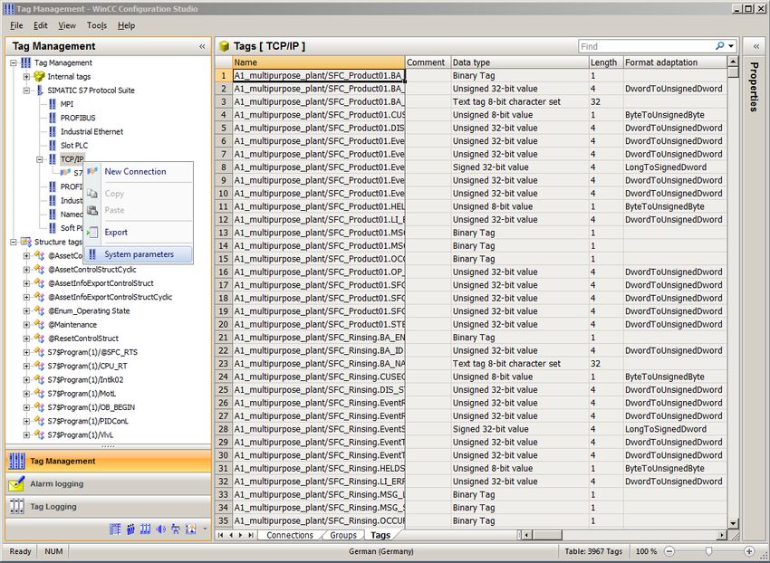
7. To set the network configuration, open Tag Management. ( Tag Management Open)
8. You can change the system parameters here. To do so, you must select the system
parameters in the SIMATIC S7 Protocol Suite under TCP/IP. ( SIMATIC S7 Protocol Suite
TCP/IP System parameters)
For unrestricted use in educational / R&D institutions. © Siemens 2020. All rights reserved. 31
p02-01-hmi-generation-v9-tud-0719-en.docxLearn-/Training Document | PA Module P02-01, Edition 02/2020 | Digital Industries, FA
9. In the 'Unit' tab, set PLCSIM.TCPIP.1 as the logical device name. ( Unit Logical device
name: PLCSIM.TCPIP.1 OK)
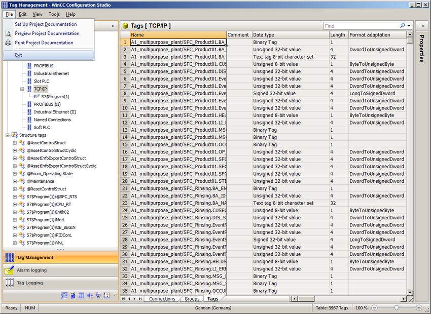
10. Close Tag Management. ( File Exit)
For unrestricted use in educational / R&D institutions. © Siemens 2020. All rights reserved. 32
p02-01-hmi-generation-v9-tud-0719-en.docxLearn-/Training Document | PA Module P02-01, Edition 02/2020 | Digital Industries, FA
11. Open the Picture Tree Manager. ( Picture Tree Manager Open)
12. The order in which the pictures will be called later is specified in the Picture Tree Manager.
For unrestricted use in educational / R&D institutions. © Siemens 2020. All rights reserved. 33
p02-01-hmi-generation-v9-tud-0719-en.docxLearn-/Training Document | PA Module P02-01, Edition 02/2020 | Digital Industries, FA
13. Keep and save the structure and close the editor. ( File Save Close)
14. Then open the OS Project Editor. ( OS Project Editor Open)
For unrestricted use in educational / R&D institutions. © Siemens 2020. All rights reserved. 34
p02-01-hmi-generation-v9-tud-0719-en.docxLearn-/Training Document | PA Module P02-01, Edition 02/2020 | Digital Industries, FA
15. The motor configuration and the screen resolution can be selected under 'Layout' in the OS
Project Editor. In addition, there are settings for the message display, the visible areas, the
window arrangement in the Runtime window and other basic settings. Set the desired layout,
the number of area keys and the monitor configuration. ( Select layout Select monitor
configuration 'Detail…' button Number of Areas Horizontal / Vertical: 2 OK)
For unrestricted use in educational / R&D institutions. © Siemens 2020. All rights reserved. 35
p02-01-hmi-generation-v9-tud-0719-en.docxLearn-/Training Document | PA Module P02-01, Edition 02/2020 | Digital Industries, FA
16. Exit the dialog with 'OK'. ( OK)
For unrestricted use in educational / R&D institutions. © Siemens 2020. All rights reserved. 36
p02-01-hmi-generation-v9-tud-0719-en.docxLearn-/Training Document | PA Module P02-01, Edition 02/2020 | Digital Industries, FA
8.5 Editing the faceplate for the multipurpose plant
1. The faceplates are created in the Graphics Designer. The best way to open individual
screens is to double-click on the name in the right window. ( Graphics Designer
A1_multipurpose_plant)
For unrestricted use in educational / R&D institutions. © Siemens 2020. All rights reserved. 37
p02-01-hmi-generation-v9-tud-0719-en.docxLearn-/Training Document | PA Module P02-01, Edition 02/2020 | Digital Industries, FA
2. The Graphics Designer provides a wide range of functions for creating process pictures.
They can be hidden or shown in the menu with View/Toolbars. ( View Toolbars)
Zoom Color palette
Alignment palette
Work area
Object Properties Standard
Layer bar Dynamic Wizard Styles
These toolbars have the following functions:
– Standard palette: Contains icons and buttons to execute frequently used commands
quickly.
– Color palette: Allows the assignment of colors to selected objects (one of 16 standard
colors or a user-defined color).
– Zoom palette: Sets the zoom factor (in percent) for the active window.
– Styles: Changes the appearance of a selected object. Depending on the object, the
line/border type, the line/border weight, the line end styles or the fill pattern can be changed.
– Standard: Contains the standard objects (polygon, ellipse, rectangle, etc.), smart objects
(OLE control, OLE element, I/O field etc.) and Windows objects (button, check box etc.).
– Dynamic Wizard: Provides numerous frequently used functions. These can be created with
the help of a dialog that guides and assists the user.
– Layer palette: Selects which of the 32 levels (level 0 to 31) is visible. Level 0 is selected by
default.
– Alignment palette: Allows you to change the absolute position of one or more objects and
the position of selected objects relative to each other or to standardize the height and width of
several objects.
– Object properties: Allows you to view and change all properties of the selected object.
For unrestricted use in educational / R&D institutions. © Siemens 2020. All rights reserved. 38
p02-01-hmi-generation-v9-tud-0719-en.docxLearn-/Training Document | PA Module P02-01, Edition 02/2020 | Digital Industries, FA
– Object palette: Shows you which object is currently selected and offers different options for
manipulation.
3. By creating faceplates, the pictures already contain block icons, which can be positioned
within the pictures as desired.
For unrestricted use in educational / R&D institutions. © Siemens 2020. All rights reserved. 39
p02-01-hmi-generation-v9-tud-0719-en.docxLearn-/Training Document | PA Module P02-01, Edition 02/2020 | Digital Industries, FA
4. The name displayed in the faceplate can be specified in the properties of the block icons.
Otherwise, a very long name that includes the path is displayed. Leave the name unchanged.
( Properties Object Name A1_multipurpose_plant/SFC_Product01)
For unrestricted use in educational / R&D institutions. © Siemens 2020. All rights reserved. 40
p02-01-hmi-generation-v9-tud-0719-en.docxLearn-/Training Document | PA Module P02-01, Edition 02/2020 | Digital Industries, FA
5. Now, you change the background color of the picture to white. To do so, left click in the
background of the picture with activated Object Properties toolbar. The properties of the
picture object open.
6. Each object as well as the picture itself has numerous properties that can be changed
statically or dynamically (for example, connected to process tags). The background color will
be edited here. ( Picture Object Colors Background Color Edit)
For unrestricted use in educational / R&D institutions. © Siemens 2020. All rights reserved. 41
p02-01-hmi-generation-v9-tud-0719-en.docxLearn-/Training Document | PA Module P02-01, Edition 02/2020 | Digital Industries, FA
7. Select white as the color (255 255 255). (white OK)
8. For the change of the background color to become effective, the global color scheme must
be deactivated. ( Picture Object Effects Global Color Scheme No)
For unrestricted use in educational / R&D institutions. © Siemens 2020. All rights reserved. 42
p02-01-hmi-generation-v9-tud-0719-en.docxLearn-/Training Document | PA Module P02-01, Edition 02/2020 | Digital Industries, FA
9. Now, change the picture geometry so that it can be displayed completely in the work area
(1920x847) at the screen resolution configured in section 8.4 (1920x1080). ( Picture Object
Geometry Picture Width: 1920 Picture Height: 847)
10. Next, in the Standard palette, click on Rectangle and draw a large rectangle in the picture.
( Standard palette Rectangle)
For unrestricted use in educational / R&D institutions. © Siemens 2020. All rights reserved. 43
p02-01-hmi-generation-v9-tud-0719-en.docxLearn-/Training Document | PA Module P02-01, Edition 02/2020 | Digital Industries, FA
11. Arrange the icons for the SFCs as shown below next to the rectangle you just drew.
8.6 Configuring the picture change
1. If the Dynamic-Wizard is not yet displayed, open the selection for the toolbars. ( View
Toolbars Dynamic Wizard)
For unrestricted use in educational / R&D institutions. © Siemens 2020. All rights reserved. 44
p02-01-hmi-generation-v9-tud-0719-en.docxLearn-/Training Document | PA Module P02-01, Edition 02/2020 | Digital Industries, FA
2. If the toolbar for the Dynamic Wizard is displayed, double-click the 'Picture change in
working area' function in the Picture Functions to open it. In order for this function to be
applied to the rectangle you have just created, it must be selected first.
( Picture Functions Picture change in working area)
3. Read the explanation and click 'Next'. ( Next)
For unrestricted use in educational / R&D institutions. © Siemens 2020. All rights reserved. 45
p02-01-hmi-generation-v9-tud-0719-en.docxLearn-/Training Document | PA Module P02-01, Edition 02/2020 | Digital Industries, FA
4. Select 'Mouse click' as the trigger. ( Mouse click Next)
5. Now select the picture that is to be changed to. ( )
For unrestricted use in educational / R&D institutions. © Siemens 2020. All rights reserved. 46
p02-01-hmi-generation-v9-tud-0719-en.docxLearn-/Training Document | PA Module P02-01, Edition 02/2020 | Digital Industries, FA
6. In the Picture Browser, select 'T1_educt_tanks.Pdl'. ( T1_educt_tanks.Pdl OK)
7. The name of the picture was applied and you confirm with 'Next'. ( Next)
For unrestricted use in educational / R&D institutions. © Siemens 2020. All rights reserved. 47
p02-01-hmi-generation-v9-tud-0719-en.docxLearn-/Training Document | PA Module P02-01, Edition 02/2020 | Digital Industries, FA
8. The wizard is closed with 'Finish'. ( Finish)
9. If you would like to view the result, you will find the mouse and the mouse click under
'Events'. With a double-click on the icon, you can then view the created C script. (
Object Properties Events Mouse Mouse click OK)
For unrestricted use in educational / R&D institutions. © Siemens 2020. All rights reserved. 48
p02-01-hmi-generation-v9-tud-0719-en.docxLearn-/Training Document | PA Module P02-01, Edition 02/2020 | Digital Industries, FA
10. Using static texts, rectangles and the Dynamic Wizard, design your picture as shown here.
Be sure that the language in the 'View' menu corresponds to the desired target language.
Here: English (United States). ( View Language English)
8.7 Editing the faceplate for T1_educt_tanks
1. Next, open the picture 'T1_educt_tanks' from WinCC Explorer.
For unrestricted use in educational / R&D institutions. © Siemens 2020. All rights reserved. 49
p02-01-hmi-generation-v9-tud-0719-en.docxLearn-/Training Document | PA Module P02-01, Edition 02/2020 | Digital Industries, FA
2. After you have changed the background color to white and the size to 1920x847, as you did
previously for the picture of the multipurpose plant, open the library.
( Show library )
For unrestricted use in educational / R&D institutions. © Siemens 2020. All rights reserved. 50
p02-01-hmi-generation-v9-tud-0719-en.docxLearn-/Training Document | PA Module P02-01, Edition 02/2020 | Digital Industries, FA
3. First, drag a symbol for the pump from the library to the work picture. ( Global Library
Symbols E-Symbols 20_2)
For unrestricted use in educational / R&D institutions. © Siemens 2020. All rights reserved. 51
p02-01-hmi-generation-v9-tud-0719-en.docxLearn-/Training Document | PA Module P02-01, Edition 02/2020 | Digital Industries, FA
4. Now also drag a valve symbol to the work picture. ( Global Library Symbols Valves
45)
For unrestricted use in educational / R&D institutions. © Siemens 2020. All rights reserved. 52
p02-01-hmi-generation-v9-tud-0719-en.docxLearn-/Training Document | PA Module P02-01, Edition 02/2020 | Digital Industries, FA
5. The static symbols can be changed in their orientation by using the button Rotate. ( Rotate
object )
For unrestricted use in educational / R&D institutions. © Siemens 2020. All rights reserved. 53
p02-01-hmi-generation-v9-tud-0719-en.docxLearn-/Training Document | PA Module P02-01, Edition 02/2020 | Digital Industries, FA
6. After you have inserted additional lines and text fields as shown here, place a rectangle for
representation of the tank and select its properties. ( Rectangle Properties)
7. To change the color, deactivate the global color scheme once again. ( Properties Effects
Global Color Scheme No)
8. Now change the background color to white. ( Properties Colors Background Color)
For unrestricted use in educational / R&D institutions. © Siemens 2020. All rights reserved. 54
p02-01-hmi-generation-v9-tud-0719-en.docxLearn-/Training Document | PA Module P02-01, Edition 02/2020 | Digital Industries, FA
8.8 Linking of picture elements with PLC tags
1. Next, you are to configure a display of the digital level sensors. For this, drag two circles into
the picture as shown here. Then, select properties of the top circle. ( Circle Properties)
2. To have the color displayed dynamically, deactivate the global color scheme. ( Properties
Effects Global Color Scheme No)
For unrestricted use in educational / R&D institutions. © Siemens 2020. All rights reserved. 55
p02-01-hmi-generation-v9-tud-0719-en.docxLearn-/Training Document | PA Module P02-01, Edition 02/2020 | Digital Industries, FA
3. Select the background color with the right mouse button and then select the dynamic dialog
in order to implement a dynamic display. ( Properties Colors Background Color
right-click in Dynamic column Dynamic Dialog)
4. In the next dialog, first select Boolean as the data type. Then, change the color for Yes/TRUE
to green. Finally, select and expression 'Tag' for the dynamization. ( Data Type: Boolean
Yes/TRUE Tag …)
For unrestricted use in educational / R&D institutions. © Siemens 2020. All rights reserved. 56
p02-01-hmi-generation-v9-tud-0719-en.docxLearn-/Training Document | PA Module P02-01, Edition 02/2020 | Digital Industries, FA
5. For the tags, select 'STEP 7 Symbol Server' as the data source. There, for the symbols, input
I70.0 for the 'level monitoring educt_tank B001 operating point H'. ( Data source STEP 7
Symbol Server A1.T1.A1T1L001.LSA+.SA+ / E70.0 / level monitoring educt tank B001
operating point H OK)
Note:
– If you are using the AS1/S7-400, select the symbols under S7 Program(1). If you are using
the AS2/RTX Box, however, you must select the symbols under S7 Program(2).
For unrestricted use in educational / R&D institutions. © Siemens 2020. All rights reserved. 57
p02-01-hmi-generation-v9-tud-0719-en.docxLearn-/Training Document | PA Module P02-01, Edition 02/2020 | Digital Industries, FA
6. Now, check the settings in the Dynamic Dialog. ( Check Close OK)
For unrestricted use in educational / R&D institutions. © Siemens 2020. All rights reserved. 58
p02-01-hmi-generation-v9-tud-0719-en.docxLearn-/Training Document | PA Module P02-01, Edition 02/2020 | Digital Industries, FA
8.9 Saving in the project library
1. The steps presented above will also be performed for the sensor 'A1.T1.A1T1L001.LSA-.SA-
/ I70.1 / level monitoring educt_tank B001 operating point L'. Then, the elements shown here
will then be selected together and grouped. Leave enough space for a valve to be placed on
the line between the tank and pump. Also take into account the function line on the pump (
A1.T1.A1T1L001.LSA-.SA- / I70.1 / level monitoring educt_tank B001 operating point L
Group Group)
For unrestricted use in educational / R&D institutions. © Siemens 2020. All rights reserved. 59
p02-01-hmi-generation-v9-tud-0719-en.docxLearn-/Training Document | PA Module P02-01, Edition 02/2020 | Digital Industries, FA
2. The group is then copied. ( Copy)
3. Now, open the library and paste the group in the project library. Name the template
'educt_tank_V1_0'. ( Project Library Paste)
For unrestricted use in educational / R&D institutions. © Siemens 2020. All rights reserved. 60
p02-01-hmi-generation-v9-tud-0719-en.docxLearn-/Training Document | PA Module P02-01, Edition 02/2020 | Digital Industries, FA
8.10 Adapting the orientation of the faceplates
1. Next, in the picture 'T1_educt_tank.Pdl', you will position the faceplates for the valve
'A1T1X004' and for the pump 'A1T1S001' as shown here. It is recommended that the
symbols within the layer be brought to the front so they cannot be covered up by other
drawing elements. ( Arrange Order Objects Bring to Front).
For unrestricted use in educational / R&D institutions. © Siemens 2020. All rights reserved. 61
p02-01-hmi-generation-v9-tud-0719-en.docxLearn-/Training Document | PA Module P02-01, Edition 02/2020 | Digital Industries, FA
2. The orientation of the dynamic valve faceplates is not yet correct. At runtime, the faceplates
are animated in such a way that they are perpendicular to the run of the pipe in closed state
and are rotated parallel with the run of the pipe in open state. However, a change of the
orientation can only take place via the CFC of the respective valve. To rotate a valve, first
open the associated CFC and then the object properties of the valve block.
( SIMATIC Manager Plant View A1T1X004 VlvL Object Properties).
For unrestricted use in educational / R&D institutions. © Siemens 2020. All rights reserved. 62
p02-01-hmi-generation-v9-tud-0719-en.docxLearn-/Training Document | PA Module P02-01, Edition 02/2020 | Digital Industries, FA
3. Now, in the 'Create block icon' field, enter a "2". This rotates the icons by 90 degrees. (
Create block icon 2 OK)
For unrestricted use in educational / R&D institutions. © Siemens 2020. All rights reserved. 63
p02-01-hmi-generation-v9-tud-0719-en.docxLearn-/Training Document | PA Module P02-01, Edition 02/2020 | Digital Industries, FA
4. After you have made the changes for all valves that are located on a vertical pipe, compile
the changes. ( SCE_PCS7_Prj PLC Compile and Download Objects OS(1)
Edit)
5. In the last dialog of the settings, select 'Changes' as the scope and start compiling the OS.
( Scope Changes Apply Start)
For unrestricted use in educational / R&D institutions. © Siemens 2020. All rights reserved. 64
p02-01-hmi-generation-v9-tud-0719-en.docxLearn-/Training Document | PA Module P02-01, Edition 02/2020 | Digital Industries, FA
6. In WinCC, the symbol of the valve for which you made the change shown is now rotated by
default. Insert a static text 'T1 educt_tank' to facilitate orientation during operation. The result
is shown below.
For unrestricted use in educational / R&D institutions. © Siemens 2020. All rights reserved. 65
p02-01-hmi-generation-v9-tud-0719-en.docxLearn-/Training Document | PA Module P02-01, Edition 02/2020 | Digital Industries, FA
7. Just as for the picture 'T1_educt_tank', a tank/reactor will now be created in the pictures for
the product tanks and reactors. You can orient yourself to the two figures below for this. In
addition, create a template for the library from the one reactor as well as from the product
tank.
For unrestricted use in educational / R&D institutions. © Siemens 2020. All rights reserved. 66
p02-01-hmi-generation-v9-tud-0719-en.docxYou can also read