LightSail 2 ADCS: From Simulation to Mission Readiness
←
→
Page content transcription
If your browser does not render page correctly, please read the page content below
LightSail 2 ADCS:
 From Simulation to Mission Readiness
 By Ms. Barbara A. PLANTE1), Dr. David A. SPENCER2), Dr. Bruce BETTS3), Mr. Sean CHAIT2),
 Dr. John M. BELLARDO4), Mr. Alex DIAZ5), and Mr. Ich PHAM1)
 1)
 Boreal Space, Hayward, CA, USA
 2)
 Georgia Institute of Technology, Atlanta, GA, USA
 3)
 The Planetary Society, Pasadena, CA, USA
 4)
 California Polytechnic University, San Luis Obispo, CA, USA
 5)
 Ecliptic Enterprises Corporation, Pasadena, CA, USA

 (Received 24 Dec, 2016)

 After the success of the first LightSail Mission (LS1) in May/June 2015, the LightSail team met in December 2015 at
 the Planetary Society headquarters to conduct a full mission review and set objectives for the next mission, LightSail 2 (LS
 2). The team identified hardware and software changes to the spacecraft baseline, and discussed enhancements to the
 ADCS subsystem. Unlike LS1, which flew in an elliptical orbit reaching under 400km minimum altitude, LS2 will fly in a
 circular orbit above 700 km, a more advantageous sailing environment.
 One sailing method considered and modeled was the detection of orbital inclination change due to solar radiation
 pressure (SRP) as presented in the work by Stolbunov, et al. This option was ultimately rejected since the spacecraft would
 not be in a truly SRP dominated orbit and modeling results showed that the 32 square meter sail would not allow for an
 observable inclination change over the anticipated mission duration. An apogee raising method using the On/Off switching
 method proposed by McInnes was explored, which would increase the semi-major axis of the orbit enough to be readily
 measured during the mission. “On” has the solar sail normal parallel to the sun vector, in the process gaining orbital energy
 while “Off“ has the sail normal perpendicular to the sun vector. Sail orientation requires a 90-degree slew maneuver twice
 an orbit. Encouraging modeling results for the apogee raising method drove the decision to use it for the solar sailing
 demonstration mission.
 Specifics of the hardware and software used to control solar sail deployment, on-orbit imaging, and other aspects of
 the spacecraft have been the subject of other papers by the LightSail team. With respect to ADCS, spacecraft attitude is
 determined using 4 magnetometers, 5 solar angle sensors, one 3-axis gyro which acts as the primary angular rate sensor,
 and one 3-axis gyro as the backup. Attitude control is accomplished using 3 variable dipole magnetic torque rods and 1
 60mNms reaction wheel. A discussion of the testing and characterization of the ADCS hardware is presented, and the
 apogee raising concept is characterized. ADCS flight software is described, including operational modes, timing
 considerations, and fault detection strategies. System and long-duration testing of the integrated software on the flight
 vehicle, which exercises the entire mission CONOPS, serves to mitigate risks and sets the stage for mission readiness of
 LightSail 2.

 Key Words: LightSail, ADCS, Simulation, Solar Sailing, CubeSat

1. Introduction Space, Hayward, CA, and Half Band Technologies, San Luis
 LightSail is a flagship program of The Planetary Society Obispo, CA, providing subsystem design and development
(TPS), an organization with over 40,000 active members support. California Polytechnic University at San Luis Obispo
worldwide which has, among other key objectives, “to (Cal Poly) would lead environmental testing of the spacecraft
empower the world's citizens to advance space science and and the Poly-Picosatellite Orbital Deployer (P-POD)
exploration” (The Planetary Society, 2015). integration effort, as well as coordinate launch approval
 In 2009, then Planetary Society Executive Director Lou activities. The Georgia Institute of Technology (Georgia
Friedman initiated the LightSail program to demonstrate solar Tech), Atlanta, Georgia, would lead the mission operations
sailing in low earth orbit (LEO) using the standard 3U and ground data system, with Cal Poly providing spacecraft
CubeSat form factor. The program moved ahead and by tracking and mission operations support.
2011, the LightSail 1 mechanical assembly was complete and In January 2013, Georgia Tech’s Prox-1 mission, to
successful deployment tests had been conducted (Biddy, demonstrate proximity operations relative to a deployed
2012). However, due to the lack of a viable launch CubeSat, was selected for implementation by the Air Force
opportunity to the desired 800km orbit and other Office of Scientific Research/Air Force Research Laboratory
programmatic reasons, TPS paused the program in 2012 until University Nanosatellite Program (Okseniuk, 2015).
further notice. Spurred on by member interest in LightSail, TPS refocused its solar sailing program on building two
TPS reviewed its options with the help of an advisory panel, spacecraft, LightSail 1 (LS1) and LightSail 2 (LS2). In order
reformulated the program plan and, in 2013, re-activated the to capitalize on a NASA ELaNa program launch opportunity,
program with a new management and technical team. which would provide a less than ideal orbit for solar sailing,
 Ecliptic Enterprises Corporation was selected to complete LS1 mission objectives were limited to checkout of spacecraft
the integration and testing program for LightSail, with Boreal on-orbit operations and demonstration of solar sail

 1
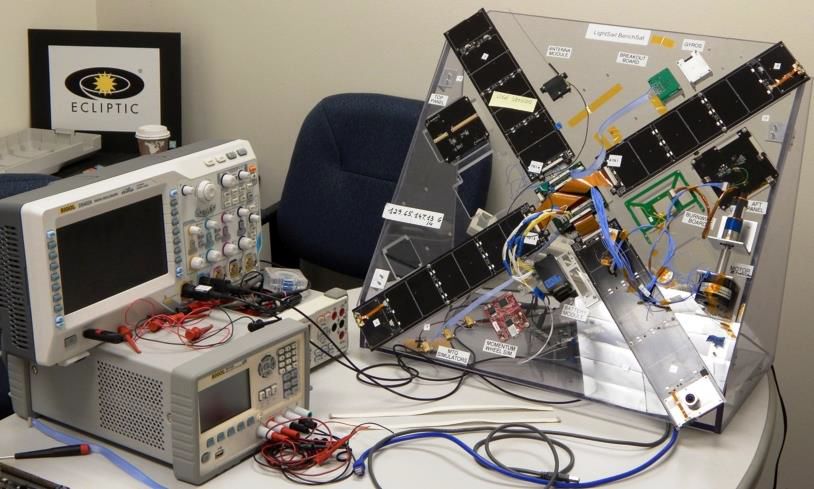
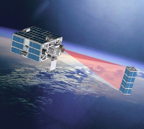
deployment. An agreement was reached between TPS and
Georgia Tech to incorporate the LS2 spacecraft in the Prox-1
mission. Following launch as a secondary payload, Prox-1
would deploy LS2 and use it as a cooperative target for
rendezvous and proximity operations. After completing its
primary mission, Prox-1 would image LightSail solar sail
deployment for downlink to the Georgia Tech ground station.
LS2 would expand LS1 mission objectives to include the
demonstration of solar sailing in low Earth orbit.
 LightSail 1 was launched in May 2015 and was closely
followed by domestic and international media. On June 9th,
after several eventful weeks on-orbit, Planetary Society CEO
Bill Nye declared the mission a success. Figure 1 shows an
image of the deployed solar sail taken on June 8th, 2015 by a
camera on-board LS1. Fig. 2. LS2 deployment and imaging by Prox-1

 LS2 is detumbled using magnetometer and solar angle
 sensor inputs to the ADCS B-dot control algorithm, which
 commands three torque rods to null spacecraft rates. Detumble
 is expected to take approximately 2 hours to complete after
 which ground operations commands LS2 into Z-Alignment,
 pointing the spacecraft antenna in the direction of the earth’s
 magnetic field, providing an attitude for ground
 communication.
 On-orbit checkout (OOC) of LS2 is planned for 2 days after
 deployment during which time the operations team will
 analyze subsystem health and status from beacon telemetry.
 The spacecraft clock is set by ground command and Two Line
 Element sets are uploaded to support SGP-4 orbit propagation.
 When the spacecraft is in sunlight, the ground commands
 Fig.1. LightSail 1 solar sail deployed in Low Earth Orbit images to be taken from the inward-facing, panel-mounted
 cameras. The images are downlinked to allow the ground team
 In July of 2015, the LightSail team conducted a detailed to evaluate camera performance. A series of momentum wheel
planning workshop to capture lessons learned from LS1 and test commands is uploaded to the spacecraft and queued for
identify design changes to support new LS2 objectives execution. When commanded, the wheel test starts and runs
(Spencer 2016). TPS, with the support of the LightSail team, autonomously to completion. Data from the wheel test is
has communicated on-going LS2 development activities in written to an on-board log for downlink and comparison to
technical papers, popular media, and Jason Davis’ blog (Davis results obtained during ground testing. On Mission Day 20,
2014). LS2 deploys its solar panels and the spacecraft is evaluated for
 This paper describes the LS2 ADCS subsystem from readiness to commence solar sail deployment.
concept to final integration and mission readiness. After deploying LS2, Prox-1 navigates into a 150m trailing
 orbit relative to LS2 to demonstrate station keeping and
2. LS2 CONOPS rest-to-rest transfer maneuvers. Ground operations commands
 After completion of flight qualification, LS2 is Prox-1 to maneuver to within 50 m of LS2. Prox-1 conducts a
encapsulated in the Prox-1 ESPA-class spacecraft in Natural Motion Circumnavigation (NMC) of LS2 from a
preparation for launch from Cape Canaveral, Florida on a passively safe orbit, enabling 360 degree imaging of LS2 in
SpaceX Falcon Heavy launch vehicle. After deployment of the visual and infrared. Finally, Prox-1 re-establishes its
Prox-1 into a circular orbit at 720km altitude, 24 degree trailing orbit with LS2 in preparation for imaging the solar sail
inclination, it performs a 5-day checkout after which it slews deployment.
to a deployment attitude (cross-track ejection), initiates the On Mission Day 21, LS2 ground operations commands
P-POD burnwire, and deploys the LightSail 2 3U CubeSat for solar sail deployment. Solar panel mounted cameras image the
an approximate 6 week mission. Prox-1 acquires visual and deployment at a basic operating sequence tailored to bracket
infrared images of LS2 every 0.25 seconds for 3 minutes after the ~2.5-minute solar sail deployment sequence: seven
deployment and then every 10 seconds for 27 minutes (Figure minutes of full-resolution imaging (1600 x 1200 pixels) per
2). camera, for up to 32 images per imaging sequence. Prox-1
 LS2 solar panels and sail remain stowed as the flight images the sail deployment from its 150 m trailing orbit. After
processor is powered on and batteries begin charging. The a successful sail deployment, ADCS transitions to Solar
telemetry beacon is activated and ground sites begin Sailing mode and LS2 accelerates away from Prox-1 through
monitoring for the first beacons from the spacecraft. Mission Days 21-49.

 2
ADCS telemetry is collected and analyzed by the ground Excel spreadsheet known as the ADCS Requirements
team to compare on-orbit behavior to simulation results. If Verification Matrix (RVM), which serves as a tracking tool
desired, modifications to existing algorithm gains can be for both requirements and test verification activities.
uploaded to experiment with and potentially optimize
spacecraft control. The apogee altitude is expected to increase Table 1. LS2 ADCS Use Cases
by roughly 700 m/day during this mission phase. After 28 Use Case Description
days of solar sailing, it is expected that atmospheric drag at LS2 ADCS 000 Mission CONOPS Overview
perigee will preclude further apogee raising. LS2 ADCS 001 Power On and Reboots
 After primary mission goals have been achieved, additional LS2 ADCS 002 Ground Contacts,
activities are planned to further demonstrate the value of LS2 Commanding and Telemetry
as an experimental laboratory for solar sailing. These activities LS2 ADCS 003 Modes and States
include commanding off nominal orientations of the LS2 ADCS 004 On-Orbit Checkout
spacecraft, sail tensioning, additional changes to algorithm LS2 ADCS 005 Solar Panel Deployment
gains, manually commanding of the momentum wheel, and LS2 ADCS 006 Solar Sail Deployment
removing all actuated control of the spacecraft in the LS2 ADCS 007 Solar Sailing
No_Torques ADCS mode.
 LS2 ADCS 008 Extended Mission

3. ADCS High-Level Requirements
 4. ADCS Design
 High-Level requirements for the ADCS subsystem are as
 LightSail spacecraft hardware, including the deployment
follows:
 mechanism and sail, has been described in previous papers,
 • Provide attitude knowledge to within 5 degrees per
 (Ridenoure, 2015). The ADCS sensor and actuator hardware
 axis during all mission phases.
 baseline is summarized in Table 2.
 • Sun sensors provide data on the angle of light
 incidence to the sensors to within +/- 3 degrees
 Table 2. LS2 Sensors and Actuators
 accuracy.
 Component Number Vendor
 • Magnetometers provide attitude knowledge of the
 Sun Sensors 5 Elmos
 body-fixed x-, y-, and z-axes to within +/- 5 degrees
 Magnetometers 4 Honeywell
 relative to the Earth magnetic field.
 • Sample spacecraft angular rates using gyro sensors. Primary Gyro 1 Analog Devices
 • Prior to solar sail deployment, provide attitude Intrepid Gyro 1 Tyvak
 control to within 10 degrees per axis. Torque Rods 3 Strass Space
 • Be actively controllable in each of its three-axes. Momentum Wheel 1 Sinclair
 • Accommodate a tip off rate of up to 25 degree/sec Interplanetary
 per axis from P-POD deployment.
 • Damp attitude rates within 2 hours of P-POD 4.1. Modeling and Simulations
 deployment. LS1 ADCS incorporated 2Hz and 10Hz Bang-Bang control
 • Utilize torque rods to achieve attitude control to algorithms for the spacecraft stowed and deployed
 within 10 degree per axis prior to solar sail configurations respectively. After sail deployment, the
 deployment. Bang-Bang control was modified by a principle known as
 • Utilize a momentum wheel to achieve 90-degree Input Shaping (Banerjee, 2001) to damp out sail vibrations by
 slew maneuvers about one axis in < 5 minutes. exercising proportional control of the torque rods. However,
 • Prior to sail deployment, be capable of providing an given the elliptical orbit of 356 x 705km, the drag effects at
 angular acceleration of 0.1 degrees/s^2 per axis. perigee overpowered attempts at sail control.
 • Following solar sail deployment, be capable of After LS1 was flight qualified and encapsulated for launch,
 providing an angular acceleration of 0.0005 the team turned its attention to other possible approaches to
 degrees/sec^2 per axis solar sailing control for LS2. One option was to keep the solar
 • Detumble from a maximum of 10 degrees per second sail in a minimum drag configuration and demonstrate
 per axis after sail deployment. inclination change of the spacecraft (Stolbunov, 2013). The
 • Align +Z axis of the spacecraft with the magnetic LS2 circular orbit at 720km is a high enough altitude to study
 field with maximum variation once settled of < 60 the combined effects of solar radiation pressure and
 degrees. atmospheric drag acting on the spacecraft.
 • Downlink telemetry for sensors, actuators and
 performance data. 4.1.1. Inclination Change
 In February of 2015, Boreal Space began modeling studies
 Use Cases provide detailed descriptions of LS2 CONOPS of inclination change using Matlab/Simulink. Work was
actions and events (Table 1). The Use Cases, in conjunction performed in three phases; 1) model a pointing controller that
with high-level requirements, facilitate the derivation of included LightSail sensors and actuators 2) model the z-axis
low-level requirements that drive the ADCS design. alignment controller and 3) model orbital inclination change.
Requirements and associated Use Cases are captured in an Magnetometers were assigned 5 degrees of uncertainty in

 3
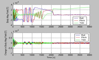
direction and solar angle sensors 3 degrees uncertainty in
direction. Gyros were not modeled in the first phase.
Magnetorquers with a maximum 1Am^2 torque authority
provided roll and pitch axis control with a reaction wheel
controlling yaw axis motion (max 0.06 Nm).
 Disturbances modeled included drag, solar radiation
pressure, gravity gradient, magnetometer misalignment,
magnetorquer misalignment and residual dipole. The
simulation used an 11 degree tilted magnetic field dipole
model rotating with the earth, with field strength of 22.7 micro
tesla at a mean altitude of 625km. A PID controller with cross
coupling cancellation was constructed, with a bandwidth of
0.004 Hz (limited by the sensor noise and the Dipole strength)
and 1 second sampling time, with 0.2 second oversampling Fig. 4. B=11.4 microTesla; 1σ pointing error = 5.3 degrees
sensors limited by the sensor noise and the Dipole strength
with 3rd order 0.03Hz Low Pass Filter (LPF).
 Results show that for a typical Earth magnetic field B, the
1σ sun pointing error is about 1.8 degrees (Figure 3). The time
varying Earth magnetic field is the main contributor to the
error. The yaw error is well controlled by RWA and is very
small compared to Roll and Pitch errors. The system is only
marginally stable if the Earth magnetic field is half of the
typical value (Figure 4.).
 Next, a Z-axis alignment controller was modeled using
magnetometers and gyros while actuating the torque rods and
momentum wheel. Gyro uncertainty is ~1 degree per axis.

 Fig. 5. Linear detumbling of spacecraft

Fig. 3. B=22.7 microTesla; 1σ pointing error = 1.8 degrees

 The algorithm aligns the spacecraft to the Earth magnetic
field by controlling the Roll and Pitch of the B vector. Figure
5 shows linear detumbling from 0 to 500 seconds with dB/dt
settling after 300 seconds. The bandwidth is 0.02 Hz, limited
 Fig. 6. Spacecraft z-axis alignment to magnetic field
by the magnetometer sensor noise.
 The momentum wheel is turned on at t=500 seconds and is
commanded between 500 and 1000 seconds. The resulting Inclination pointing, adopted from Stolbunov, was
RPM depends on wheel inertia and the B field. Torque Rods simulated using a distributed control law that continuously
 varies the sail angles throughout the spacecraft orbit. The
generate opposite torques. The gyros are turned on and the
 simulation model uses the simplified 11 degrees tilted Dipole
switch to angular velocity controller occurs at 1000 seconds.
 magnetic field.
Pitch and roll controls are weak around 90 degrees alignment
 Assuming that r̂ S⊙ = the sun vector, N̂ = a vector normal to a
because the B field is very small around the Z-Axis.
 solar sail modeled as a reflective flat plate and t̂ = a vector
 Figure 6 shows a rapid alignment of the spacecraft z-axis to
 aligned with the spacecraft velocity, all being unit vectors in
the magnetic field when the algorithm switches to the
 ECI coordinates, then the optimal inclination for an SRP
z-alignment controller at t=2000 seconds. After settling, the
 dominated case is expressed mathematically as follows:
primary gyro can be turned off if there are power
considerations, however the z-axis angular velocity slowly
 αN = α⊙ Eq. (1)
drifts depending on the disturbances.

 4
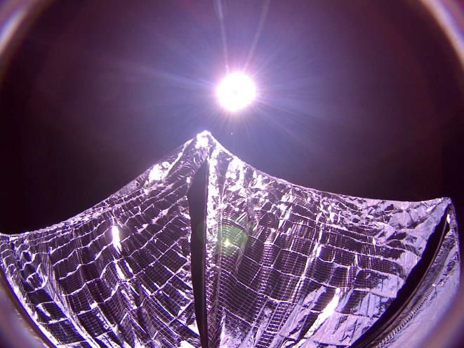
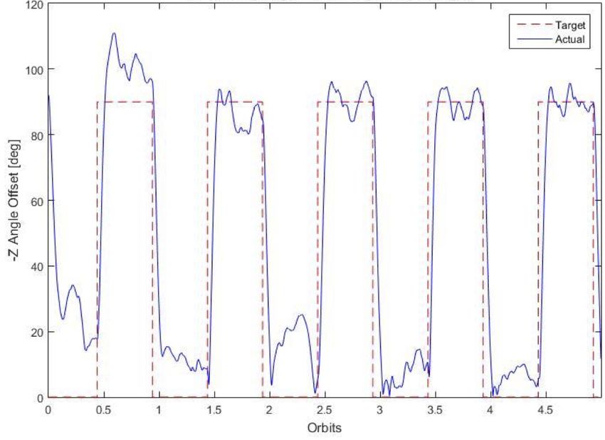
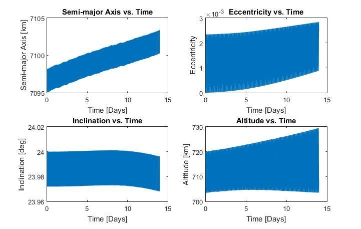
tan βN = (3 tan β⊙ ± √9 tan2 β⊙ + 8) / 4 Eq. (2) 4.1.2. Apogee Raising
 Using a 6 Degree of Freedom (6 DOF) Matlab/Simulink
where αN = yaw of the N̂ vector, α⊙ = yaw of the r̂ S⊙ vector, βN simulation at the Georgia Institute of Technology, an On/Off
= pitch of the N̂ vector, and β⊙ = pitch of the r̂ S⊙ vector. For the approach for raising the orbit and increasing semi-major axis
simulations, pitch and yaw are modeled in degrees. and orbital energy was evaluated. The On/Off strategy,
 Simulations were run with a circular orbit period of 5951 adopted from McInnes (McInnes, 1999), is illustrated in
seconds, and a sun direction vector = [1 0 0]. For initial Figure 9. The control implementation aligns the sail normal
conditions, r = [7098 0 0] km and velocity v = [0 6.9 3] with the sun vector when the spacecraft is moving away from
km/sec. Figure 7 shows optimal pointing angles resulting in a the sun in the geocentric orbit, and aligns the sail normal
positive inclination. orthogonal to the sun direction when the spacecraft is moving
 toward the sun. Starting from a circular orbit, the effect of this
 control strategy is to increase orbit velocity when outbound
 from the sun, thus raising orbit apogee on the opposite side of
 the orbit.

 Fig. 7. Optimal Pointing Angles – Positive Inclination

 Figure 8 shows pointing errors of for a B field of 23
microTesla. The 1σ pointing error is 4.1 degrees. For a
magnetic field strength of 40 microTesla, the 1σ error
 Fig. 9. On/Off control strategy for apogee raising

 Mathematically, the apogee raising control strategy can be
 expressed as:

 = − , • > 0 Eq. (3)
 = − , • < 0 Eq. (4)

 where is the solar sail normal unit vector, is the unit
 vector direction from the spacecraft to the Sun, and is the
 spacecraft velocity vector, with all vectors expressed in the
 Earth-centered inertial coordinate system. Implementation of
 this approach requires 90-degree slew maneuvers twice per
 Fig. 8. B=23 MicroTesla; Pointing Errors
 orbit.
 When modeled in the 6 DOF simulation environment, with
improves from 4.1 to 2.6 degrees. Pointing errors increase perfect attitude knowledge and control, the result is a secular
significantly when the z component of the magnetic field is increase in orbit semi-major axis, as shown in Figure 10.
small. With attitude knowledge and control errors incorporated, the
 The change in orbital inclination that would result from this expected ADCS performance compared with the desired
control strategy over a 60-day period is quite small, less than attitude profile is shown in Figure 11. The resulting
0.01 deg. This is due to the fact that the 720 km nominal semi-major axis versus time is shown in Figure 12. The
orbital altitude is in a regime where solar radiation pressure is expected rate of increase of apogee is 700 m/day over the first
only marginally greater than atmospheric drag (roughly a 14 days of solar sailing. By day 28 of solar sailing, the
factor of two greater, depending upon solar activity perigee altitude will decay to the point that atmospheric drag
conditions), the LightSail 2 solar sail area to mass ratio is offsets solar radiation pressure, and it will no longer be
fairly low (6.4 m2/kg), and the attitude knowledge and control possible to increase apogee.
errors result in pointing errors of the solar sail normal of up to The Simulink model for the On/Off control strategy was
30 deg. Because the small change in orbital inclination may autocoded into the C programming language for flight
not be easily observed over the course of the mission, the software implementation.
alternate strategy of apogee raising was evaluated.

 5
4.2. ADCS Algorithms Perturbations (SGP-4) algorithm, with flight heritage on prior
 Boreal Space and Georgia Tech co-created an Algorithm Cal Poly CubeSat missions, to perform LS2 orbit propagation.
 Design Document (ADD) to serve as an Interface Control
 Document (ICD) for both groups and to guide software 4.3. ADCS Flight Software
 development for LS2. The ADD details ADCS process LS2 flight software and firmware are written in the C
 sequencing and algorithm interactions, including fault programming language, and execute on a Tyvak Intrepid
 detection and responses. processor board. A Linux-based operating system hosted on
 Intrepid features libraries, (e.g., event handling, command
 handling) and kernel space drivers (e.g., SPI, I2C, RTC) that
 support FSW development.
 The FSW driver library provides low-level application
 programming interfaces (API’s) to sensors and actuators.
 ADCS Process Management running at 1 Hz controls program
 flow through interactions with the driver library and the
 ADCS algorithms. The attitude control algorithm is accessed
 via function calls and is driven by data exchanges defined in
 the Algorithm Design Document. ADCS FSW implements the
 operational modes shown in Table 3.

 Fig. 10. Secular increase in semi-major axis with On/Off control Table 3. ADCS Modes
 strategy and perfect pointing. Mode Description
 Detumble Null angular rates
 Z-Align Ground pointing attitude
 Sailing Apogee raising
 No_Torques Torque rods and wheel not
 actuated
 Recharge Low power mode
 Extended Mission Performance tests

 Spacecraft commands are parameterized to maximize
 flexibility for testing and mission operations. All mode
 transitions can be commanded from the Ground. The only
 autonomous mode transition occurs during the on-orbit wheel
Closed Loop Performance (3 of 6) test, where a transition from Z-Align to Detumble after test
 completion nulls angular rates imposed by the wheel. ADCS
 Fig. 11. Angle between solar sail normal and the Sun, with attitude states (stowed, panels deployed and sail deployed) reflect
 knowledge and control errors included. physical configurations of the spacecraft that require different
 sets of gains and are changed autonomously after deployment
 events.
 Processor reboots were experienced frequently during the
 LS1 mission. An enhanced configuration table in persistent
 memory tracks spacecraft modes, states, errors and sensor and
 actuator status to establish an ADCS baseline for both initial
 power-on, and after a processor reboot.
 Timing considerations in the FSW include function
 callbacks (polls) to manage the momentum wheel, gyros,
 torque rod phasing in relation to magnetometer sensor
 Fig. 12. Semi-major axis grows ~700 m/day during the first 14 days of readouts (to prevent interference), and system manger process
 solar sailing, with expected ADCS performance. status requests. Queue-driven command processing for the
 momentum wheel allows flexibility to conduct experiments
 An appendix to the ADD is an Excel spreadsheet that on-orbit.
 defines inputs required by the attitude control algorithm such LightSail telemetry is downlinked via a 220-Byte beacon
 as sensor readings, gains, etc. The spreadsheet defines the packet at a nominal 15-second cadence. Spacecraft logs can be
 outputs from the algorithm that command the actuators for downloaded which help to further characterize spacecraft
 spacecraft attitude control. Upon completion of simulation behavior.
 testing and autocoding, Georgia Tech delivered the algorithm ADCS fault management detects and reports on invalid or
 code to Boreal Space for integration into the ADCS flight anomalous events. Commanding errors include invalid
 software. ADCS also includes a Simplified General parameter lengths, invalid data such as Two Line Element sets

 Closed loop performance shows roughly 0.7
 6 km/day increase in apoapsis
 altitude
 22
that do not pass a checksum test, and invalid deployment validated, and a polarity error for the momentum wheel was
states. A wheel speed check prevents the momentum wheel found and fixed in flight software. The solar angle and gyro
from being commanded past a threshold rate by the ADCS sensors were tested and found to be performing nominally.
algorithm. A dynamic configuration table directs restart of the Once the FSW was nearly complete, long duration tests
ADCS process after an unexpected processor reboot. were conducted first on BenchSat and later on LS2 to verify
On-board error reporting can be cleared by ground command. software behavior over extended periods of time. Operational
 Readiness Tests (ORT’s), which involved all mission
5. Integration and System Testing personnel, were run to validate the LS2 CONOPS in a
 Preliminary ADCS software development and testing was “flight-like” manner. Commands were verified, and telemetry
performed on a standalone Intrepid Board, to which a Payload collected for trending and evaluation by the mission
Interface Board (PIB) was later added as the direct interface to operations team. While actual solar panel and sail
ADCS hardware. FSW development activities are facilitated deployments can’t be tested on BenchSat, these activities have
by a BenchSat, shown in Figure 13, which consists of most of been validated in separate tests of the flight unit at Cal Poly.
the hardware components on the LightSail spacecraft. For As of this writing, all planned testing of the LS2 spacecraft
missing subsystem components, simulators have been is complete with test procedures in place and test data
incorporated as proxies, e.g., a momentum wheel simulation. archived for comparison to on-orbit spacecraft performance.

 6. Conclusion
 The LS1 mission served as an important engineering
 pathfinder for the goal of demonstrating solar sailing in Low
 Earth Orbit. The brief mission gathered valuable information
 on spacecraft and sail behavior, as well as providing flight
 experience for the operations team. The data analysis and
 lessons learned from LS1 provided a knowledge base from
 which to define expanded mission goals for LS2.
 The simulation and evaluation of solar sailing concepts has
 been a key area of investigation for LS2. Given the relatively
 short mission duration, an apogee raising approach was
 selected, modeled and integrated into the ADCS FSW. In
 order to facilitate on-orbit investigations of spacecraft
 Fig. 13. BenchSat Test System behavior in relation to simulations, ground commands can
 modify algorithm control parameters. Manual control of
 Based on reports that the LightSail magnetometers were spacecraft actuators provides the ability to experiment with
“noisy”, they were the first sensors to be tested on BenchSat. response to controlled torques. Sail tensioning and
Sensor readings were out of the expected range of magnetic non-nominal spacecraft orientations are planned for the
field measurements according to NOAA predictions for the extended mission phase. Imagery taken by the nearby Prox-1
BenchSat location (NOAA, 2016) spacecraft will provide an unprecedented perspective of LS2
 Out-of-range values were also recorded from both prior to and post solar sail deployment.
magnetometers on the flight unit. Ecliptic Engineers brought LightSail missions are paving the way for solar sailing
the Flight Unit to the University of California, Los Angeles within our solar system, to interstellar space, and to our
(UCLA) for calibration testing in a Helmholtz cage. During closest neighboring star, Alpha Centauri. The Breakthrough
testing, the –Y panel magnetometer was found to be Starshot initiative (Davis, 2016) recognizes solar sailing as a
non-functional, and was subsequently invalidated in the way to ‘leave the fuel behind’ for space travel, using lasers to
ADCS FSW. Sensor characterization showed that the accelerate small spacecraft to 20 percent speed of light. The
magnetometer readings were out of range, and that LightSail team is proud to be making a contribution towards
calibrations needed to be applied. The LS2 motor was found defining a pathway to the stars.
to have a varying effect on magnetometer readings in the
stowed state based on motor positions. It was decided that a Acknowledgments
single calibration would be applied in the deployed state.
Fortunately, in the stowed state, delta magnetometer readings The authors would like to thank the ~40,000 members of
vs. absolute readings are sufficient to support the ADCS The Planetary Society, key donors, and the 23,331
algorithm for spacecraft detumbling. contributors to its LightSail Kickstarter campaign conducted
 Sensor and actuator hardware characterization continued in during spring 2015. These interested and generous people
May 2016 at the Space Dynamics Lab in Logan, Utah. In funded these missions, and their support was essential. Lou
addition to isolating the magnetometers in a Helmholtz cage, a Friedman deserves credit for keeping the vision of a solar
2-degree of freedom platform allowed for characterizing the sailing demonstration mission alive since 1976, and Bill Nye
behavior of the torque rods and momentum wheel while under
 for being a tireless champion for science and technology.
ADCS control. The max dipole for each torque rod was

 7
References
 1) Banerjee, A. (2001): “Reducing Minimum Time for Flexible Body
 Small-Angle Slewing With Vibration Suppression,” J. of
 Guidance, Control, and Dynamics, March-April, pp. 1040–443.

 2) Biddy, C. and Svitek, T. (2012 May 16): “LightSail-1 Solar Sail
 Design and Qualification,” Paper/presentation for 41st Aerospace
 Mechanisms Symposium, held at JPL on 2012 May 16-18. From
 the symposium proceedings, pp. 451-463.

 3) Davis, J. (2014): LightSail Is Happening, and I’ll Be Your New
 Guide. Available at:
 http://www.planetary.org/blogs/jason-davis/2014/20140602-lightsa
 il-is-happening.html (last accessed Dec 23rd, 2016).

 4) Davis, J. (2016): Planetary Society solar sails paved way for Alpha
 Centauri starshot. Available at:
 http://www.planetary.org/blogs/jason-davis/2016/20160421-lightsa
 il-starshot.html (last accessed Dec 23rd, 2016).

 5) McInnes, C. R., (1999): Solar Sailing, Technology, Dynamics and
 Mission Applications, Springer-Praxis Series in Space Science and
 Technology, Praxis Publishing, Chichester, UK.

 6) National Oceanic and Atmospheric Administration (NOAA) NCEI
 Magnetic Field Calculators (2016)
 https://www.ngdc.noaa.gov/geomag-web/#igrfwmm (last accessed
 Dec 23rd, 2016).

 7) Okseniuk, K. J., Chait, S. B., Schulte, P. Z. et al. (2015): “Prox-1:
 Automated Proximity Operations on an ESPA-Class Platform”,
 presented at 29th Ann. AIAA/USU Conf. on Small Satellites,
 Logan, UT, August, Paper SSC-15-IX-4.

 8) Ridenoure, R. et al. (2015): “LightSail Program Status: One Down,
 One to Go,” presented at Ann. AIAA/USU Conf. on Small
 Satellites, Logan, UT, August, Paper SSC-15-V-3.

 9) Spencer, D. et al. (2016): “Testing the LightSail Program:
 Advancing Solar Sailing Technology Using a CubeSat Platform”,
 JoSS, Vol. 5, No. 2, pp. 531-550

10) Valentine Stolbunov, Matteo Ceriotti, “Optimal Law for Inclination
 Change in an Atmosphere through Solar Sailing,” Journal of
 Guidance Control and Dynamics, Vol 36, Sept-Oct 2013, pp
 1310-1323.

11) The Planetary Society (2015): About Us, Our Founders. Available
 at: http://www.planetary.org/about/our-founders/ (last accessed
 Dec 23rd, 2016).

 8
You can also read