Management System for Tattoo Studio - Juli'a Medina Velasco - DDD - UAB
←
→
Page content transcription
If your browser does not render page correctly, please read the page content below
TFG EN ENGINYERIA INFORMÀTICA, ESCOLA D’ENGINYERIA (EE), UNIVERSITAT AUTÒNOMA DE BARCELONA (UAB)

        Management System for Tattoo Studio
                                              Julià Medina Velasco

     Resum– Crooked Tattoo BCN es un pequeño estudio de tatuaje situado en Ripollet, un pueblo
     en los alrededores de Barcelona. Este estudio es dirigido por dos hermanos que, por tal de
     adaptarse a las nuevas tecnologı́as y a algunos requisitos sugeridos por sus clientes, decidieron
     que serı́a beneficioso para su negocio tener un sitio web donde promocionarse. De acuerdo con sus
     peticiones, ésta web es de hecho un sistema de gestión basado en web para su negocio de manera
     que exprimir todo el potencial de su negocio y, ser capaces de comprobar el estado de su negocio.
     MSTS (Management System for Tattoo Studio) es el software que se desarrollará para ser utilizado
     en Crooked Tattoo por tal de satisfacer las necesidades y requisitos que se podrán ver a lo largo de
     éste documento. Éste software pretende ser compacto, genérico, robusto y escalable de manera
     que, en caso de ser necesario, pueda actualizarse fácilmente en un futuro.

     Paraules clau–            Model-vista-controlador, tatuaje, diseño, arquitectura, patrones, aplicación
     web, .NET, C#

     Abstract– Crooked Tattoo BCN is a small tattoo studio located in Ripollet, a town nearby Barcelona.
     This studio is managed by two brothers who, in order to adapt to new technologies and to some
     requirements raised from their clients, have decided that it would be benecial for their business to
     have a website to promote themselves. According to their requirements, this website is indeed a
     Web Business Management System (WBMS) so that they are able to squeeze all the potential of
     their business and also, be able to have a full knowledge of the status of their business. MSTS is the
     software that it is going to be developed in order to be used by the Crooked Tattoo studio in order
     to satisfy all the requirements that will be seen in this document. This software will be compact,
     generic, robust and as scalable so, if needed, could be easily updated in a future.

     Keywords–           Model-view-controller, tattoo, design, architecture, patterns, web system, .NET,
     C#

                                                                        F

                                                               States was a German immigrant, Martin Hildebrandt. He
                                                               opened a shop in New York City in 1846 and quickly be-
                                                               came popular during the American Civil War among sol-
1 I NTRODUCTION                                                diers and sailors of both Union and Confederate militaries.
            CENTURY was the time that the word tattoo
                                                               It was from this moment that tattoo artists began to open

18           (which is a loanword from the Samoan word their own studios and creating different kind of styles as for
             tatau, meaning ”to strike”) first appeared in the example:
Western world, thanks to James Cook, as an official name
                                                                  – Old School
for the practice of marking one’s body with ink.
We could say that the modern popularity of tattooing stems        – New Traditional
from Captain James Cook’s three voyages to the South Pa-
cific in the late 18th century. On Cook’s first voyage in         – Dotworck
1768, one of his officers, Sir Joseph Banks, as well as many
                                                                  – Ornamental
others of the crew, returned to England with tattoos.
The first recorded professional tattoo artist in the United       – Stencil
     • Contact E-mail: julia.medina@e-campus.uab.cat                        – Black & Grey
     • Specialization realized: Software Engineering
     • Thesis tutored by: Yolanda Benı́tez Fernández (departament de
Ciències de la Computació)
     • Course 2018/19

                                                    Gener de 2019, Escola d’Enginyeria (UAB)
2                                                                             EE/UAB TFG INFORMÀTICA: Management System for Tattoo Studio

   From that moment, the art of tattooing began to be                  Apart from the aforementioned, another reason to carry
more popular among the people and more and more tattoo              out the project from scratch is that in this way it will be eas-
studios began to be opened around Europe, being now a               ier to fulfill all the requirements obtained from the Stake-
place where are the most tattooed cities in the world, and          holder and to ensure that all parts of the project are unified
being a tattoo artist began to be considered as a job.              in the correct way and that work correctly.

   So, it is here where Crooked Tattoo, a local tattoo stu-
                                                                    3     P ROJECT P ROPOSAL
dio placed nearby Barcelona, intervenes with the proposal
of, through the use of software engineering,carrying out a          Crooked Tattoo BCN is a small tattoo studio located in
project in which a web-based management system needs to             Ripollet, a town nearby Barcelona. This studio is managed
be designed and developed in order to be able to have a bet-        by two brothers who, in order to adapt to new technologies
ter management of their tattoo studio and also, be able to          and to some requirements raised from their clients, have
adapt better to the new technologies.                               decided that it would be beneficial for their business to
The execution of this project pretends to help the Crooked          have a website to promote themselves (this was their main
Tattoo studio to promote their work among Internet and              idea, only a web site).
also, allow them to exercise a better control over their tattoo
studio (as for example to check the information about ap-              After having some conversations, we could see that,
pointments when needed by looking at their ”admin panel”,           to be able to squeeze the potential of your business and
etc.)                                                               help them to manage it in a more efficient and comfortable
All being said, this project has as its final goal the develop-     way, it would be better to carry out the development of a
ment of a scalable software that will be used to make some          web-based management system. This is how the web-based
tattoo artists job a little bit easier and providing them the op-   Management System for their Tattoo Studio (MSTS) was
portunity of managing their business in an easier way than          born.
they are doing today.
                                                                       The MSTS is the software that will be designed and de-
                                                                    veloped to have a compact, generic and robust solution for
                                                                    the issues that their business do have. This system will need
                                                                    to accomplish, according to the studio managers, the fol-
                                                                    lowing requirements:

                                                                        – Forms to request an appointment.
                                                                        – To homogenize the design for the different devices
                                                                          (mobile, tablet, web).
                                                                        – Different user roles with different permissions.

                                                                        – Being able to check the amount of benefits, appoint-
                Fig. 1: Deployment Diagram                                ments performed each month and the new users regis-
                                                                          tered.

                                                                       In order to facilitate the fact, if necessary, of applying
2    S TATE    OF THE      A RT                                     changes in the future this MSTS software, will be needed
Developing this web-based application is not something              to be developed as scalable as possible in order to easily
new, the following references are some examples [1] ,               identify the different parts of the system and the whole pro-
furthermore, this type of tool already has a name Web               cess must be well documented so that it can be understood.
Business Management System (WBMS) it is a software                  In other words, formalize the entire development process
developed to help the owners to run their website with              just in case something is needed in a future.
a business mindset. So, starting from the basis that this
already exists, why do I develop it again from zero?
                                                                    3.1     Project Objectives
   Well, the answer is that, from my point of view, this
                                                                To carry out the whole process, the following objectives are
is something really ”personal” depending on the business
                                                                considered as those that will allow to cover said project:
that will use it (different clients, different uses, etc.). For
                                                                  Under the nomenclature MSTS.OBJ.X.Y the detailed
that reason, I preferred to start from scratch so that this
                                                                explanation of each objective is as following:
software is not just one of those that already exist, but one
that is specially designed for the type of business of the
Stakeholder, a tattoo studio in this case. In this way both
the design of the front-end part and the entire back office
part will be focused on the type of users that will use both
the web and the business control system, thus offering the
best possible experience.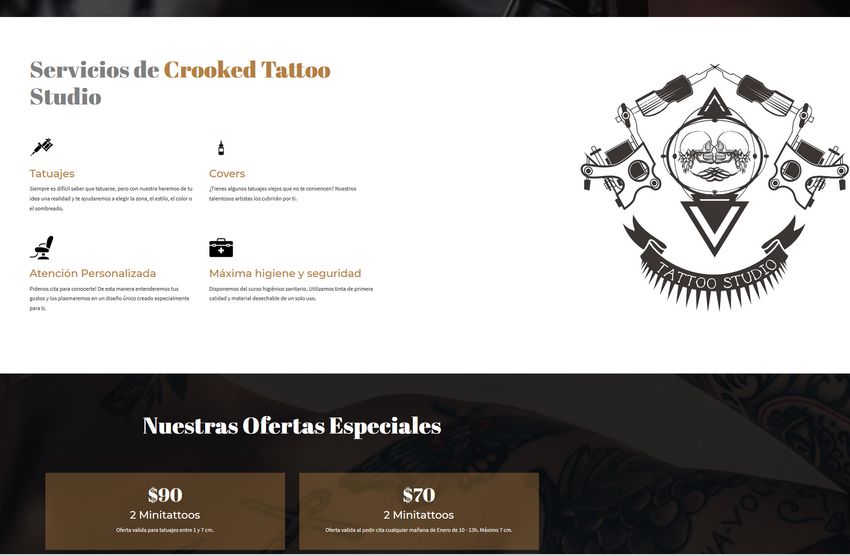
Julià: Management System for Tattoo Studio                                                                                3

                                                    Fig. 2: Objectives Tree

   – MSTS.OBJ.0 – Software Engineering: consists of
     developing software engineering and apply it to the
     project in all its facets, starting from an elicitation, or
     requirements gathering , going through the previous
     study and analysis, arriving at the development of the
     project and finally, the validation of the software de-
     veloped. Starting from this base, the following main
     objectives appear:                                                 Fig. 3: .net framework architecture diagram
   – MSTS.OBJ.1 – Research: Conduct an initial study to
     know the environment that will fit the best to execute
                                                                        – CLR: The Common Language Infrastructure or
     the project, language, frameworks, etc. To do this, a
                                                                          CLI is a platform on which the .Net programs are
     phase of information gathering on each part must be
                                                                          executed. It has the following key features:
     executed individually, giving rise to the parts shown
     below:                                                             * Exception Handling - Exceptions are errors
   – MSTS.OBJ.1.1 – C#: General object-oriented pro-                      which occur when the application is executed.
     gramming language for networking and especially                    * Garbage Collection - Garbage collection is the
     suitable for Web development. With C# it is possible to              process of removing unwanted resources when
     process the information of forms, generate pages with                they are no longer required.
     dynamic content, or send and receive cookies, among
                                                                        * Working with Various programming languages
     many more things, which is really helpful as the MSTS
     will be a dynamic web application.
                                                                        – Class Library: The .NET Framework includes a
   – MSTS.OBJ.1.2 – Bootstrap: Is a free and open-source                  set of standard class libraries. A class library is
     framework for designing websites and web applica-                    a collection of methods and functions that can be
     tions. It contains HTML based design templates for                   used for the core purpose.
     typography, forms, buttons, navigation and others.                 – Languages: The types of applications that can be
     These provide a modern appearance for formatting                     built in the .Net framework is classified broadly
     text, tables and form elements. This will be extremely               into the following categories:
     useful to develop the front-end.
   – MSTS.OBJ.1.3 – .NET: The .Net framework is a col-                  * ASP.Net – This is used for developing web-
     lection of programming support for what are known as                 based applications, which are made to run on
     Web services, the ability to use the Web rather than                 any browser such as Internet Explorer, Chrome
     our own computer for various services. It can be used                or Firefox.
     to create both - Form-based and Web-based applica-                 * ADO.Net – This technology is used to develop
     tions. This framework has a basic architecture that is               applications to interact with Databases such as
     shown below:                                                         Oracle or Microsoft SQL Server.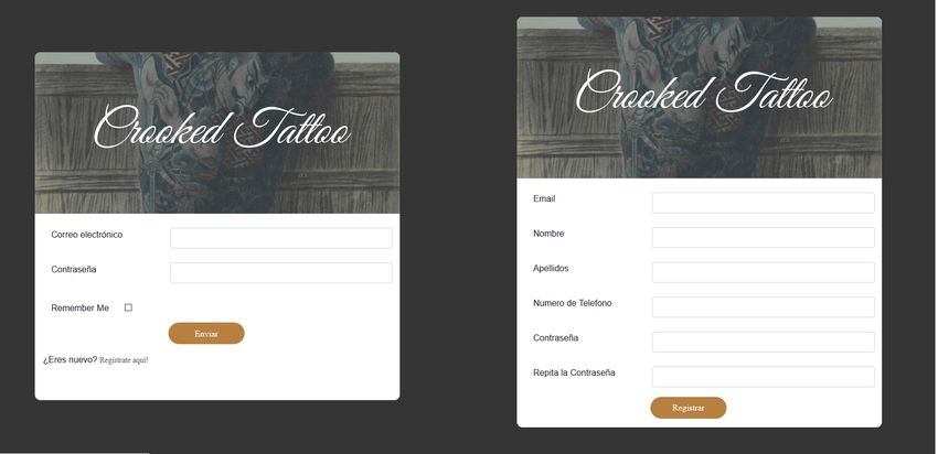
4                                                                        EE/UAB TFG INFORMÀTICA: Management System for Tattoo Studio

    – MSTS.OBJ.1.4 – APIs: An application programming 4 W ORKING M ETHODOLOGY
      interface (API) is a set of subroutine definitions, com-
      munication protocols, and tools for building software. The methodology that has been followed to carry out this
      Within this project, the use of APIS will be needed in project, has been an agile working methodology known as
      order to proceed with a complete & easy solution.          SCRUM. But, it is note pure SCRUM, since this methodol-
                                                                 ogy is more focused on carrying out group work instead of
    – MSTS.OBJ.1.5 – Requirements Gathering: In or- individual work, but an adaptation of it as this project is be-
      der to have a global vision of the desired final sys- ing carried out just by one person. That means that myself
      tem, a requirement gathering must be carried out with is the one who will be planning the activities, the sprints
      the Stakeholder to understand the needs that impelled and the meetings with the Stakeholders (the Tattoo studio
      them to request said system and, to discover the re- owners and my tutor).
      quirements for the system, the scope and the restric- SCRUM consists on planning out small iterations of time
      tions of the system.                                       in which objectives are defined and work is carried out in
    – MSTS.OBJ.2 – Analysis: A correct realization of the order to meet them. To achieve these objectives, a daily
      reason of being of this project is carried out and it must monitoring of the work done the previous day is carried out
      be recorded in a detailed documentation the point from so that, if necessary, changes can be applied in the planning
      which this project starts, the desired scope as well as and specify the tasks that will be carried out throughout the
      how the project’s execution is going to be managed.        day. Said iterations of time, within the scope of SCRUM,
                                                                 are called Sprints, which, as we have mentioned before, is
    – MSTS.OBJ.3 – Design: This objective focuses on the period in which the work itself is executed. Using this
      how the software that implements the project will be methodology, I plan 2 weeks sprints, that could change if
      developed.                                                 needed to 4 weeks sprints, so that it coincide with the meet-
    – MSTS.OBJ.3.1 – Database: The database (DB) is one ings I hold with my project tutor.
      of the most important parts of the MSTS since having In order to have a good planning I use the tool ”Trello” that
      an organized and well-structured database is key for allows establishing a list with different tasks to be carried
      this project as the web application will have different out and distributing them between tasks ”in progress” or
      sections and, we will need to store in an orderly man- ”finished”. So we have a simple way to visualize the tasks
      ner all the necessary information.                         that remain to be done, those that have already been done
      In order to create a structured DB, an En- or the ones that are being carried out. It is ideal to keep a
      tity–relationship model has been created to specify good control of the work and also fits very well to the needs
      there all the parts of the DB as well as the relations proposed by this project.
      between the tables.
    – MSTS.OBJ.3.2 – Front-End: To develop the front-end 5 P LANNING
      part of the web application, it will first be necessary to
      design it and have it approved by the Stakeholder. The In order to perform this project from beginning to end, a
      design of this part will be based mainly on offering the planning has been prepared which mentions the tasks that
      best User Experience possible.                             must be completed at all times. These tasks have been
                                                                 divided between activities and sub-activities that together
    – MSTS.OBJ.4 – Software Development: Based on
                                                                 make up this project. To carry out this planning, a Gantt
      the objective MSTS.OBJ.3 this objective, must comply
                                                                 Chart has been created where these activities are estab-
      with the above information. In this way, the develop-
                                                                 lished, the time dedicated to each activity and the relation-
      ment of the code will be carried out respecting the op-
                                                                 ship between them. Apart from this, the deadlines estab-
      timal procedure for any software engineering project
                                                                 lished in the project itself have been taken into account.
      as well as respecting the guidelines and the documen-
                                                                 Those deadlines are the following:
      tation established to carry it out.
    – MSTS.OBJ.4.1 – Front-End: Development of the nec-            – Nov.11th 2018 – First progress report.
      essary software to, based on the designs, to create all
      the views that will be displayedin the application.          – Dec.23rd 2018 – Second progress report.
    – MSTS.OBJ.4.2 – Back-End: Development of the nec-             – Jan.27th 2018 – Final report proposal.
      essary software to, based on the work-flows designs,
      provide internal logic to all the processes of the web       – Feb.10th 2018 – Presentation proposal.
      application.
    – MSTS.OBJ.4.3 – Back-Office: Development of the               – Feb.11th 2018 – Final delivery.
      necessary software to provide functionality for inter-
                                                                   – Feb.17th 2018 – Poster delivery.
      nal operations. It will be developed as easy to use as
      possible so that the administrator will be able to apply
                                                                   – Feb.18th to 21st 2018 – Defense of the project .
      any change in an intuitive manner.
    – MSTS.OBJ.4.4 – Css styles: Development of the nec-           Broadly speaking, the Gantt Chart consists of three main
      essary software to create all the styles that will be used blocks which encompasses almost all the activities. These
      on all the views.                                          blocks are: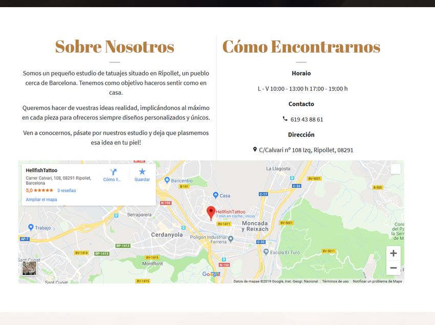
Julià: Management System for Tattoo Studio                                                                                    5

    • Research: Carry out a preliminary study on the project         • Main entities: These entities represent items that are
      to look for other similar applications and websites and          present in the same physical store, such as users, prod-
      how investigate how were realized, in order to have a            ucts, appointments, etc. That is, are those tangible
      preliminary information and, be able to prepare a plan-          things that we can extract from a real business model
      ning the realization of the project.                             to our web model.
    • Design: Realize an initial design based on the desir-
                                                                     • Support entities: These entities represent items of re-
      able properties of all software and the restrictions set
                                                                       lationship, grouping, distinction, etc. that help to make
      by the Stakeholder, such as the execution of a modular
                                                                       sense of the main entities. For example: a table that
      and scalable software.
                                                                       relates users to their respective roles. In real life we
    • Development: Create the software, by following the               know that a user is a tattoo artist, but when interpret-
      designs that had been already done.                              ing this information in an application we need this type
   There are three activities that are not covered by the              of ”supplement” to be able to discern the artists among
blocks mentioned before as they cover the whole project.               the rest of users.
Those activities are: Management System for tattoo
studio(the project itself), Software Engineering(the
process used to develop the project) & Documentation.

  If it is desired to take a look at this Gantt Chart, it can be
found in the 11 Section

6     D EVELOPMENT C YCLE
6.1      Requirements Gathering
Before giving way to the design and implementation stages,
it is necessary to carry out a preliminary and exhaustive
analysis to determine the requirements that the project must
meet. With this stage it is possible to reflect with clarity
and precision the different characteristics of the system
(requirements) classified between functional requirements
(what the system must include) and non-functional require-
ments (system constraints, performance requirements, etc.).                            Fig. 4: E-R Diagram

   For this, a Software Requirements Specification docu-
ment has been made with which it is tried to obtain a bet-         6.2.2   Front-End Design
ter understanding of the problem and the specific aspects
that must be developed to solve said problem as well as the        With the design of the visual interface of the applica-
main functionalities to develop and what is it expected for        tion, some requirements came up when conversing with the
the software product to do and not do.. This document spec-        Stakeholders:
ifies the requirements that the software must comply with,
as well as a priority and impact of each requirement.                • The interface must be responsive

                                                                     • The design shall be striking but clean, without to many
6.2      Design
                                                                       things on it
Talking about the design, it is possible to distinguish three
main parts:                                                          • The interface shall be intuitive and easy to use
    • Model Design
                                                                      In order to create the design I worked side by side with
    • Front-End Design                                             the Stakeholders taking profit of their ideas and artistic
    • Application logic Design                                     skills. From that point we all started do some freehanded
                                                                   draws on a blank paper and that way I captured their main
                                                                   idea of the design and also, I commented on some of the
6.2.1     Model Design
                                                                   defects that the designs could have and made several rec-
The model was created from the requirements gathering              ommendations until finally we got a design that fitted all
stage since, within them it is possible to understand the dif-     their requirements and seemed to please everyone. Once
ferent parts that will form the system. The model is the           this was finished, I took a couple days to study this de-
most important part of this project, since it is the extraction    sign until our next meeting within two days where I com-
of real life to an application so that we are managing to rep-     mented them some problems that might appear and finally,
resent a physical store and the management of its business         we ended up with a final-design that was approved by the
logic in a web application.                                        Stakeholders and that was realistic at the same time that fit-
The model consists of two different types of main entities:        ted the requirements.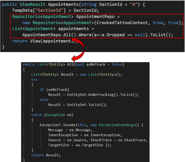
6                                                                           EE/UAB TFG INFORMÀTICA: Management System for Tattoo Studio

6.2.3   Application logic Design                                                           Administrator
This type of design refers to the usability and the flow of in-
formation that allow to carry out the use of the application.
In this, all the functionalities of the actors that intervene in
the application are defined.
   Below are the functions that make up the system, de-
pending on the type of user that is using the web application.

                      Anonymous User

                                                                                 Fig. 8: Administrator User Case

                                                                   6.3    Implementation
                                                                   The implementation of the project has been performed by
                                                                   following the flow explained below: First of all, the model
                                                                   was created in a database hosted on a local SQL Server. To
                                                                   translate the Transact-SQL code and adapt it to the model, I
                                                                   have opted to use the Entity Framework (EF) that is offered
                                                                   by Microsoft[2]. This tool is an Object-Relational-Mapping
             Fig. 5: Anonymous User Use Case                       (ORM), which allows us to relate a model of persistence
                                                                   data with our model at a higher level in our application us-
                      Registered User                              ing instances of our classes. That is, it allows us to relate the
                                                                   data model of a database with the data model in C# classes.
                                                                   This method of work is more commonly known as Database
                                                                   First, that is to say, from a database model, the classes of
                                                                   the C# model are automatically generated and already in-
                                                                   ternally related to each other.
                                                                   From this point is where the ViewModels appear [3]. As
                                                                   the name indicates, they are in charge of relating neces-
                                                                   sary information from the model and the view, in such a
                                                                   way that they will pick up what they need from the fields of
                                                                   the model to show it in the view to the user. It represents
                                                                   the data that it is wanted to be displayed on a view/page,
                                                                   whether it will be used for static text or for input values
                                                                   (like textboxes and dropdown lists) that can be added to
              Fig. 6: Registered User Use Case                     the database (or edited). A ViewModel can have two main
                                                                   modification flows:
                            Artists                                  • It can be modified in the view by the user through a
                                                                       form and end in the data model in a nagged manner.
                                                                     • It can be populated in the data access layer (DAO /
                                                                       Generic Repository (the explanation of this pattern can
                                                                       be found in Section 7) and shown informatively in the
                                                                       view.
                                                                      The development process has been systematic for each of
                                                                   the functionalities or use cases previously explained.
                                                                     1. Create the ViewModels by defining the ”fields” that
                                                                        will be necessary to obtain from the users. When doing
                                                                        this, in order to provide some ”logic” to those forms,
                   Fig. 7: Artist Use Case                              data annotations have been used in order to manage
                                                                        the data definition in a single place and do not need re-
                                                                        write the same rules in multiple places. Those tags are
                                                                        helpful to enforce validation rules, specify how data
                                                                        from a class /member is displayed in the UI and specify
                                                                        the intended use of class member and the relationship
                                                                        between classes.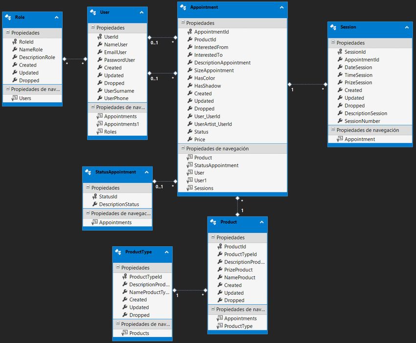
Julià: Management System for Tattoo Studio                                                                                    7

    2. Create the way to retrieve / modify / insert the infor-         the database without worrying about the connection,
       mation in the data access layer (DAO / Generic Repos-           the context, and other configuration methods that are
       itory).                                                         being already inherited from GenericDAO.
                                                                       To apply this pattern correctly, the methods that appear
    3. Create the view without logic, just the items that are          in each class will be to extract information related to
       desired to be shown and used in a future. Taking profit         the class in which they are found, for example:
       from the data annotations used in the ViewModels,
       here, in the views, the Unobtrusive Validation has been
       used. This type of validation uses HTML5-compatible             if at any point it is wanted to obtain the number
       ”data-” attributes to store all of the information it needs     of registered users in 2019, we would add a new
       to perform validation so, it is possible to implement           method ”GetRegisteredUsers (int year)” to the Users-
       simple client-side validation without writing a ton of          DAO class. In this way, we are encapsulating and de-
       validation code, and that the user experience can be            coupling information by layers and by models.
       improved simply by adding the appropriate attributes
       and including the appropriate script files.
    4. Develop the business logic in the controller. For ex-
       ample, in order to create a new session for a tattoo, the
       following steps are done:
          • First, the appointment under which a new session
            it is desired to be created is retrieved.
          • A new session is created and related to the ap-
            pointment by using the unique Id of it.
          • After that, each property of the new session is                 Fig. 10: Model-View-Controller Pattern
            populated with the data received from the view
            in the ViewModel.                                        • Model - View - Controller (MVC): This pattern is
          • The, it is needed to fill out the audit or historical      one of the most popular in the world of web develop-
            fields(date of registration, modification).                ment. It is based on 3 main pillars:
          • Finally, the ORM is used to persist the informa-
                                                                          – Model: It contains the classes that represent the
            tion in the Database.
                                                                            model of a real world of flat objects. These ob-
    5. Knot the information following the MVC data flow.                    jects would be users, tattoo sessions, products,
                                                                            etc. In addition to them, it will also contain
    6. Test at a functional level the possible error cases (eg:             classes to help the real model to understand it in a
       null values, incorrect information, etc.)                            computerized way, for example, the type of prod-
                                                                            uct offered, the user role , etc.
7      D ESIGN PATTERNS                                                   – View: It is the visual representation of the data,
                                                                            everything that has to do with the graphical in-
    • Data Acces Object (DAO): [4] is a design pattern that                 terface goes here. It only has to contain visual
      has the purpose of separating the access to the tables                information to be able to interact with the user,
      of the DB in a decoupled way from the rest of the app.                therefore, it will never apply business logic, but
      Basically it allows us to have a class that does not de-              logic of user experience.
      pend on anything other than itself and retrieves the in-
      formation from the database.                                        – Controller: The controller is responsible for
                                                                            managing the flow of information between the
                                                                            view (user) and the model (classes and BD). In
                                                                            this way, the controller will receive information
                                                                            generated by the user, it will interpret it and will
                                                                            tell what to do with it: check errors, redirect to
                                                                            another view, call a method of data insertion in
                                                                            BD, etc.

                                                                     • Singleton: A singleton is a class that allows only a sin-
                                                                       gle instance of itself to be created and gives access to
                                                                       that created instance. It contains static variables that
                                                                       can accommodate unique and private instances of it-
                       Fig. 9: DAO architecture                        self. It is used in scenarios when a user wants to re-
                                                                       strict instantiation of a class to only one object. This
                                                                       is helpful usually when a single object is required to
       As possible to see in the class diagram of the figure           coordinate actions across a system.
       9, simply instantiating a class SessionsDAO, it is              The reason for using this pattern in the application is to
       possible to access to any type of information from              avoid that methods that never vary and that are general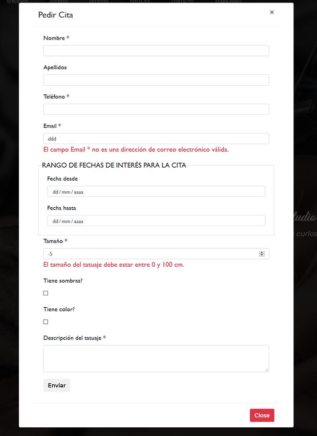
8                                                                             EE/UAB TFG INFORMÀTICA: Management System for Tattoo Studio

      throughout the application are executed in different in-       8    T EST
      stances. In this way we get, for example, that there
      is not a different instance to encrypt a password for          In order to realize a testing within the parts of this project,
      each connected user, but that there will be a single in-       different black box tests have been carried out to check
      stance in the entire application for all users. It is a good   basic functionalities such as, for example, the result of
      method to optimize the performance of the application          database-based queries, controllers functioning, etc. Next,
      in terms of memory.                                            a small example will be detailed.

                                                                        This is an example of one of the use cases made. The pur-
                                                                     pose is to verify that the Index method of the controller, re-
                                                                     turns a view with an empty content, since this way it would
                                                                     be redirecting to the url whose name has its method of ac-
                                                                     tion, in this case ”Index”.

                                                                                       Fig. 13: Use Case defined

                  Fig. 11: Singleton Pattern                            This process originates a call to perform a data collection
                                                                     of the http context.

    • Factory Pattern: This pattern allows us to have a ”fac-
      tory” of objects. In the project there is an interface
      called ”IRepository” that offers a CRUD functional-
      ity via Entity Framework to the respective DBSets. A
      class ”Repository” has been implemented as a ”fac-
      tory” that implements said interface. An adaptation
      of this pattern has been used to avoid having so many                        Fig. 14: Index method
      classes that implement the main interface as model
      classes. In order to do this, an EntitySet is defined      Initially, during this data collection, it was being assumed
      within the class that admits as a type of input a model that the context is always correct, but it reality, it could have
      of our data model. In this way we allow any model failed and caused the web application to stop.
      mapped to the BD to be accessed, modified, retrieved,
      and eliminated through a same class, simply indicating
      to it the model type when instantiating it and calling
      the method that is necessary. So, if we want, for exam-
      ple, to recover all the current Appointments, we would
      only need two lines of code as we can see in Figure
      12.                                                                         Fig. 15: Initial function

                                                                        So, by doing this simple check I have been able to realize
                                                                     the mistake and modify the method so that it also takes into
                                                                     account null values in the controller and in access to user
                                                                     data within the http context

                                                                                      Fig. 16: Corrected function

                                                                        In order to carry out these tests, NUnit has been used. An
                                                                     open source framework of Unit Tests for Microsoft .NET
             Fig. 12: Repository Usage Example                       that serves the same purpose as JUnit in java, which has
                                                                     been used during this bachelor.
Julià: Management System for Tattoo Studio                                                                                 9

                              Fig. 17: NUnit

   In summary, as in this case has happened, the testing has
helped to correct different possible errors that exist during
the intermediate processes that a method executes. That is,
the simple fact of wanting to verify that what a method re-
turns is correct, has helped to verify that the processes that
are executed to return that result are also correct and con-
trolled.

9     R ESULTS
Now, The results obtained from the development of this                      Fig. 20: Apply for an Appointment
project will be exposed. Since displaying those results
requires a considerable amount of images, in order                When an Admin user wants to apply a modification (in
not to load this document much, a part of the results will an appointment or user) the information of the form comes
be shown in this section and the rest in the appendix section. already filled with the information that contains in the DB.

   Navigation Bar - Within the Home Page, we have the
navigation bar that it is used for the users to navigate
through the web page. Here, two different pictures will be
exposed:
    • How a normal user would see the navigation bar
    • How an Admin user would see the navigation bar

                                                                                   Fig. 21: Modify forms

                                                                    Instagram API - One of the requirements made by the
                                                                 Stakeholder was that the web application shall be easy to
                      Fig. 18: Normal User view                  manage. As they are a tattoo studio, it is needed that their
                                                                 work is exposed in the web page. For that reason, Instagram
                                                                 API has been used so that they do not need to upload the
                                                                 pictures but, those will be automatically captured from their
                                                                 Instagram account.

                      Fig. 19: Admin User view

  So, if the user is has the Admin role, he will be able to
access to the Admin Panel of the web system.

   Forms - Forms are used by the users to apply for an ap-
pointment, create/modify users, create new sessions for an
appointment, etc. All the forms used in this web application
are created from ViewModels. This helps to define all data
types and add an unobtrusive validation so that the user sees
if something is wrong in the form before sending it.                               Fig. 22: Instagram Feed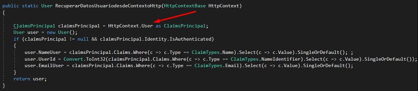
10                                                                           EE/UAB TFG INFORMÀTICA: Management System for Tattoo Studio

   Admin Panel This is the section where they will find             10.2    Future Work
information about the status of the business and where they
                                                             As future work for this project, it must be said that some
will manage their appointments, users, etc. There is some
                                                             sort of small things need to be applied. Firstly, some of
information that is displayed directly from the DB by using
                                                             the pictures that this website has will be changed (once the
queries so that they know their revenues, number of tattoos,
                                                             Stakeholders provide them to me). Secondly, I will add a
and some more information required by them.
                                                             new layer for the project, the Business Layer, in order to en-
                                                             capsulate all the methods that are applied to provide some
                                                             business logic. Once this is done, some methods that are
                                                             now in the Controllers will be simply moved to this new
                                                             layer as the Controller would not have to care about how
                                                             the business works. Finally, the Admin Panel has a ”Prod-
                                                             ucts” section that was intended to hold products to be sold
                                                             in an online store that the application would have. As per
                                                             request of the Stakeholder, because of the way how they
                                                             work, they retracted about this online store. For that reason,
                    Fig. 23: Admin Panel                     it has been left empty but I will make it to be used for them
                                                             to, internally, know about their stock (the Ink, ointments,
   In order for them to look for users/appointments, there tattooing machines and more).
is a search bar in each of the views that instantly searches Also, I will advise the Stakeholder to find for a good hosting
for the word/letter that the user is entering in each of the service and introduce them to all the integration part until
columns.                                                     the web application is fully working for everyone.

                                                                    ACKNOWLEDGEMENTS
                                                                    First of all I want to thank my tutor Yolanda Benı́tez for the
                                                                    time dedicated to guide me through this project and for the
                                                                    support and motivation offered.
                                                                    I would also like to thank my colleagues for the help given
                                                                    at times when I was stuck as well as for the advice they gave
            Fig. 24: Admin Panel - Users section                    me when I started this project.
                                                                    Finally, I want to thank my whole family for the support
                                                                    they have given me during the years that this degree has
10     C ONCLUSIONS & F UTURE W ORK                                 lasted and, especially, to my couple Laura for all her help
                                                                    and support during tough times.
10.1     Conclusions
Since the beginning of this project, I believe that the devel-      R EFERENCES
opment has been quite positive. Starting from the basis that
at first I was a bit lost regarding the web programming, I           [1] title = ”Fresh Books”
have learned to use new technologies to explore a part of                available = https://www.freshbooks.com/financial-
the computer science that I have always been interested in.              reporting/?ref=12779&utm medium=marketplaces&utm
I am also learning different software architectural patterns             campaign=business-management&utm source=capterra
that I did not know which has helped me a lot to carry out a         [2] title = ”Entity Framework-Overview”
part of this project and that for sure will be useful at anytime         available = https://www.tutorialspoint.com/entity framework/
during my future career. It should be said that at the begin-            entity framework overview.html
ning I thought that creating a web system was much more
easier than it really is, I have seen that it has lot of work        [3] author = ”Rachel Appeal”
behind in order to create a robust solution and that lots of             title = ”Use ViewModels to manage data & organize
things need to be checked.                                               code in ASP.NET MVC applications”
Thanks to the knowledge acquired during these years of de-               available = http://rachelappel.com/use-viewmodels-
gree and the help of the internet, it has been possible to de-           to-manage-data-amp-organize-code-in-asp-net-mvc-
velop a final solution that is functional and fulfills the objec-        applications/
tive of helping this tattoo studio with the basic management
of a business and improving the quality of it (an example            [4] author = ”Richard”
would be that before the creation of this web application                title = ”Que es Data Access Object” available =
they did not have any history about the appointments they                https://www.javamexico.org/blogs/richardmx/
made and now they can easily check it). Throughout the                   que es data access object
development of the project I have learned many new con-
cepts related to web development and the need to have a
good knowledge of database management, as it is vital in
most projects, as well as into the management of a small
business.
Julià: Management System for Tattoo Studio 11
11 A PPENDIX
1.1 Application Pictures
LOGIN & REGISTER
Fig. 25: Login and Register Views
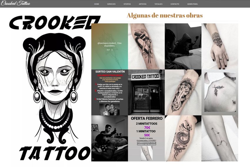
HOMEPAGE
Fig. 26: Home View12 EE/UAB TFG INFORMÀTICA: Management System for Tattoo Studio
Fig. 27: Home View
Fig. 28: Home ViewJulià: Management System for Tattoo Studio 13
Fig. 29: Tattooers Calendar
Fig. 30: Sessions Information
USER PROFILE
Fig. 31: User Profile14 EE/UAB TFG INFORMÀTICA: Management System for Tattoo Studio
Fig. 32: User Profile
GANTT CHART
Fig. 33: User ProfileYou can also read