End-to-End Quality of Service Recommendations for Mobile Networks - Network as a Service Solution Group
←
→
Page content transcription
If your browser does not render page correctly, please read the page content below
End-to-End Quality of Service
 Recommendations for Mobile
 Networks
 Network as a Service Solution Group

Date January 2021                      Document version: v1.0
Network as a Service (NaaS) | End-to-End Quality of Service Recommendations for Mobile Networks

Table of Contents
Authors                                                                                                                                  2

Table of Contents                                                                                                                        2

List of Figures                                                                                                                          3

List of Tables                                                                                                                           3

End-to-End Quality of Service Recommendations for Mobile Networks                                                                        4
   Abstract                                                                                             4

   Motivation                                                                                           4

   Reference Architecture                                                                               7

   Building Blocks                                                                                      9

   Detailed Process Walkthrough                                                                       11

   Classification                                                                                     13

   Policing                                                                                           18

   Marking                                                                                            20

   Propagation                                                                                        21

   Metering                                                                                           23

   Queuing                                                                                            24

   Transmission/Reception                                                                             27

   Active QoS Monitoring                                                                              29

   On-net Monitoring                                                                                  30

   Off-net Monitoring                                                                                 30

   General Recommendations on limited support for QoS                                                 31

   Conclusions                                                                                        32

   Passive Validation                                                                                 32

   Active Validation                                                                                  32

                                                                                                  Copyright © 2021 Telecom Infra Project, Inc.   2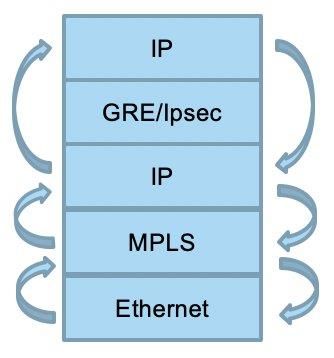
Network as a Service (NaaS) | End-to-End Quality of Service Recommendations for Mobile Networks

Glossary                                                                                                                                 33

TIP Document License                                                                                                                     36

Disclaimers                                                                                                                              37

List of Figures
Figure 1: Reference Architecture                                                                                                    7
Figure 2: Quality of Service Processing                                                                                             9
Figure 3: Edge and Transit Nodes                                                                                                 11
Figure 4: Reading the Original QoS                                                                                               21
Figure 5: QoS propagation in the network and in the node                                                                         22
Figure 6. Congestion Threshold and Max capacity in a Queue                                                                       24
Figure 7: Hierarchical QoS                                                                                                       26
Figure 8: Active QoS monitoring                                                                                                  29

List of Tables
Table 1: 3GPP QCI requirements for transport networks                                                                               6
Table 2: QCI to DSCP mappings                                                                                                    12
Table 3: Classification policies per technology                                                                                  14
Table 4. Finer Resolution                                                                                                        16
Table 5. Policing Policies                                                                                                       19
Table 6: MTU/MSS Calculation                                                                                                     28

                                                                                                  Copyright © 2021 Telecom Infra Project, Inc.   3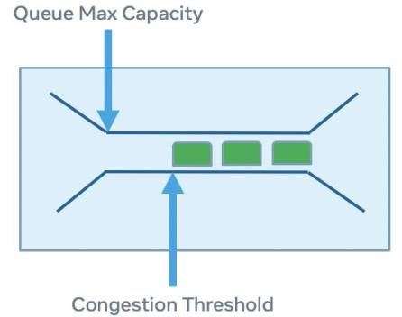
Network as a Service (NaaS) | End-to-End Quality of Service Recommendations for Mobile Networks

End-to-End Quality of Service Recommendations
for Mobile Networks
Prepared for IpT Peru by Facebook Connectivity

Abstract
This document has been prepared for Internet para Todos (IpT) Peru and includes the main components of
an End-to-End Quality of Service (QoS) schema that can be used to validate and troubleshoot a mobile
network.

Click the following links for detailed recommendations these areas:

     1. Mobile Application QoS Service Classification                                             Recommendation
     2. Classification                                                                            Recommendation
     3. Policing                                                                                  Recommendation
     4. Marking                                                                                   Recommendation
     5. Propagation                                                                               Recommendation
     6. Metering                                                                                  Recommendation
     7. Queuing                                                                                   Recommendation
     8. Transmission and Reception and recommendations for
           networks with limited QoS support:                                                     Recommendation
     9. General Recommendations on limited support for QoS Recommendation

Motivation

End-to-End QoS schemas applicable to mobile networks include multiple packet-based technologies from
RAN, Mobile Backhaul, Packet Core Networks, Ethernet to IP/Multiprotocol Label Switching (MPLS)
networks. Each network provides different alternatives to differentiate traffic and give different treatments
to the traffic depending on the network conditions.

                                                                                                     Copyright © 2021 Telecom Infra Project, Inc.   4
Network as a Service (NaaS) | End-to-End Quality of Service Recommendations for Mobile Networks

By setting up the QoS network parameters properly, service providers can achieve better quality of
experience for the critical applications running on top of them such as Voice over LTE, network
management, network synchronization and data, and multicast services. Without proper QoS
implementation, user experience can be impaired to the point where customers will be discouraged from
using the network as much as they might or could give up altogether.

Mobile networks, particularly the ones that follow 3GPP specifications, require detailed network
engineering including the following elements:

     •     Resource block allocation
     •     Quality Control Indicators (QCI)
     •     DSCPs
     •     Ethernet PCP (i.e., p bits)
     •     Multiprotocol Label Switching (MPLS) CoS/EXP bits
     •     Bandwidth Management/Traffic Engineering and overbooking factors.
     •     Delay Management

3GPP applications are specified in terms of tolerance to delay, packet losses, and bandwidth requirements.

                                                                                                  Copyright © 2021 Telecom Infra Project, Inc.   5
Network as a Service (NaaS) | End-to-End Quality of Service Recommendations for Mobile Networks
Here is an example for LTEs QCIs:
A B C D
1 QCI Resource Type Packet Delay Budget Tolerable Error Rate
2 1 GBR 100 msec 10^-2
3 2 150 msec 10^-3
4 3 50 msec 10^-3
5 4 300 msec 10^-6
6 5 Non GBR 100 msec 10^-6
7 6 300 msec 10^-6
8 7 100 msec 10^-3
9 8 300 msec 10^-6
10 9
Table 1: 3GPP QCI requirements for transport networks
NOTE: The current table is based on nine QCI values as per Release-8. It can be adjusted for 13 QCIs in
Release-12 and 15 QCIs in Release-14.
The end goal of this configuration is to deliver predictable bandwidth, delay, and packet losses across the
network to satisfy the requirements of the different applications such as voice, data and management
during network operations and different traffic conditions while delivering an excellent quality of
experience for the users and the network itself.
This document can be used as a guideline to audit an End-to-End QoS scheme for any type transport
network or as a guide to deploy system features to ensure that a QoS schema is deployed in the network
properly.
Copyright © 2021 Telecom Infra Project, Inc. 6Network as a Service (NaaS) | End-to-End Quality of Service Recommendations for Mobile Networks
Reference Architecture
The following network diagram describes the main components during an End-to-End QoS Schema Design.
Figure 1: Reference Architecture
This list includes the major components and locations where the QoS functions are enforced:
User Equipment (UE): This can be a smartphone, computer, or dongle. Voice and data APN/Zone setting for
these devices (i.e., maximum transmission unit (MTU)) should be configured properly.
BTS/RBS/eNodeB: This is the radio access node that receives the traffic from the wireless side and converts
the traffic into IP packets to be transported. Proper Radio (QCI) information to IP (DSCP) must be
configured here.
Mobile Backhaul: It is the aggregation network between the access node and the IP/MPLS network. Usually
backhaul is based in VSAT, Fiber, or metro ethernet technologies. Some service providers include a Cell Site
Router (CSR)/Cell Site Gateway (CSG) in the remote sites to connect one or multiple radio access nodes
(i.e., eNodeBs) or this feature is included in the eNodeB itself. On PE/P architecture all access functions
must be configured in the PE nodes and Per Hop Behaviors (PHB) in the P Routers.
IP/MPLS: This is the IP transport network between the sites. Usually, it is an MPLS Network (PE/P –
Edge/Core Architecture) and can be designed together with any Mobile Backhaul network (MetroE, EVPN,
VPLS) and use seamless MPLS architectures. On PE/P architecture, all access functions must be configured
in the PE nodes and per-hop behavior (PHB) in the P Routers.
Evolved Packet Core (EPC): The EPC network includes multiple components such as MME/S-GW/P-
GW/PCRF/GGSN/SGSN. These nodes should be configured with QoS parameters that are consistent with
the transport networks (Mobile Backhaul and IP/MPSL). H-QoS is required when the transport network is
dealing with different Radio Sharing schemas. EPC can be considered as an edge node so all QoS functions
Copyright © 2021 Telecom Infra Project, Inc. 7Network as a Service (NaaS) | End-to-End Quality of Service Recommendations for Mobile Networks
should be configured in these nodes as well.
Internet: This network behaves like a best effort network. QoS cannot be managed here.
Intranet: This represents any corporate network that the mobile access network is connected to. QoS
schema from the enterprise and carrier network must be design in a consistent way. H-QoS is required
when the transport network is dealing with different enterprise APNs.
Copyright © 2021 Telecom Infra Project, Inc. 8Network as a Service (NaaS) | End-to-End Quality of Service Recommendations for Mobile Networks
Building Blocks
End-to-End QoS is an engineering task that allows multiple network technologies to work together in a
consistent way to deliver predicable network behavior.
QoS is not only limited to DSCP, p bits, class of services markings in the packets.
Figure 2: Quality of Service Processing
To have an End-to-End QoS of service scheme in the network, all network elements must be harmonized to
preserve the QoS settings as they traverse the network in the protocol stack and across the network
elements regardless of the node type, this includes the following steps, as shown in the Figure 2:
1. Classification: All packets need to be properly classified by application (i.e., voice, data) or network
function. (management). This classification is the foundation for all other QoS processing steps in
the node and in the network.
2. Policing (ingress enforcement): Bandwidth will be enforced in the ingress port. i.e., uplink
scheduler resource block allocation.
3. Marking: Ensure the packet has the proper QoS settings.
4. Propagation: Higher layers to/from lower layer QoS preservation (i.e., DSCP to p-bits marking and
mapping). QoS marking should be consistent as they traverse different network domains (wireless,
IP, Ethernet or MPLS networks) and as they go in the protocol stack
(IP→Ethernet→MPLS→Ethernet). The same consideration applies as the packets travel via Internet
Protocol Security (IPsec)/GRE/GTP tunnels. The general idea is to ensure the QoS settings in the
transport layer are consistent with the application layer.
Copyright © 2021 Telecom Infra Project, Inc. 9Network as a Service (NaaS) | End-to-End Quality of Service Recommendations for Mobile Networks
5. Metering (egress enforcement): Bandwidth will be enforced in the egress port, for example:
downlink scheduler resource block allocation.
6. Queuing: All packets are temporarily stacked in a queue until they are transmitted in the wire/air.
Each interface has multiple queues to store the frames to be transmitted with different priorities.
In wireless network, downlink and uplink schedulers support different 3GPP scheduling disciplines.
For Ethernet and Transport Networks routers and switches support multiple IETF/RFCs scheduling
techniques i.e., RFC7141.
7. Transmission/Reception: This is the action of serializing the data into the physical interfaces hence
this step adds delay in the process, and it is highly dependent on the interface speed i.e., 10Gbps or
1Gbps.
NOTE: Both queuing time and transmission are delaying the frames in the system and, this delay is highly
dependent on the congestion level and length of the frames (frame size or MTU).
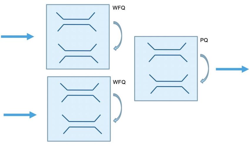
All these functions are executed at the edge of the network domains (ingress/egress nodes) and few of
them in the transit nodes (classification and queuing/transmission). This allows to speed up the processing
in the network. QoS processing in the transit nodes is also called PHBs and functions in the edge node are
also known as behavior aggregates (BAs) when DSCP classification is used.
Copyright © 2021 Telecom Infra Project, Inc. 10Network as a Service (NaaS) | End-to-End Quality of Service Recommendations for Mobile Networks
Figure 3: Edge and Transit Nodes
QoS setting must be consistent across each network element and across networks. For example, when the
traffic needs to travel across IP networks, micro-wave network or satellite network, all these networks
should have the same QoS schema.
Let’s go deeper in each building block to define some recommendations to apply during any network
design or network audit.
Detailed Process Walkthrough
Mobile Application QoS Service Classification (QCI to DSCP Mapping)
In mobile networks QoS in the packets is defined in terms of QCI. In this way, both downlink and uplink
schedulers manage the mapping between radio parameters (i.e., Resource block allocation) and IP DSCP
values.
Service providers must configure QCI to DSCP mappings in the eNodeB to secure the appropriate behavior
for wireless traffic in the air and in the transport network.
Copyright © 2021 Telecom Infra Project, Inc. 11Network as a Service (NaaS) | End-to-End Quality of Service Recommendations for Mobile Networks
The following table shows a sample of a QCI to DSCP mapping. This table is configured statically in the
eNodeB.
A B C D
1 QCI DSCP DSCP Application
2 1 EF 46 Voice (GBR)
3 2 EF 46 Video (GBR)
4 3 EF 46 Multimedia Streaming (GBR)
5 4 AF41 34 RT Gaming (GBR)
6 5 AF31 26 Signaling
7 6 AF31 26 TCP Apps - High priority
8 7 AF21 18 VoIP, Non GBR
9 8 AF11 10 TCP/UDP regular priority
10 9 BE 0 TCP/UDP low priority
Table 2: QCI to DSCP mappings
Dynamic Policy Management can be applied to change QoS settings via PCRF/Gx interfaces in the packet
gateway. These parameters can be propagated to the Serving Gateway and eNodeB for local enforcement.
This mechanism, though out of scope for this document, follows the same underlying mechanisms
presented below.
Recommendation:
1. Validate that QCI/DSCP mappings are consistent in the whole network.
2. When IPsec is enabled on a CBH satellite system features such as Transmission Control Protocol
(TCP) Spoofing, GTP acceleration, and header compression are not utilized, and satellite bandwidth
is not maximized especially in the RTN or upstream direction. Hence, time sensitive data is not
prioritized leading to delays and packet loss.
Copyright © 2021 Telecom Infra Project, Inc. 12Network as a Service (NaaS) | End-to-End Quality of Service Recommendations for Mobile Networks
Classification
This can be implemented by classification policies, similar to access control lists (ACLs), in the ingress ports
to identify the applications. Routers and switches can identify the applications via source/destination IP
Address, UDP/TCP ports, source/destination MAC address, DSCP marking, p-bits markings or any
combinations of these parameters.
The following table shows an example of a classification table that is applicable to IP/DSCP, MPLS and
Ethernet networks with a correspondence to a system supporting up to eight, four and two queues in the
interfaces.
In some cases, QoS schemas with four or two queues are supported in inexpensive devices but are not
recommended for high-capacity network or in dense areas given the limitations in delivering predictable
network behavior.
Edge functions and PHB/Transit Nodes must be based in the same classification table.
A B C D E F G H
1 Class of Application MPLS PHB DSCP 8 4 2
Service QoS Queues Queues Queues
2 1 Sync (PTP) 7 LU 56 0 0 0
3 Radio Network 7 LU 56 0 0 0
Control
4 2 Transport 6 CS6 48 1 1 1
Network
Control (OSPF,
BGP)
5 Signaling 6 CS6 48 1 1 1
6 O&M High Prio 6 CS6 48 1 1 1
7 3 Voice 5 CS5 40 2 2 2
Copyright © 2021 Telecom Infra Project, Inc. 13Network as a Service (NaaS) | End-to-End Quality of Service Recommendations for Mobile Networks
A B C D E F G H
1 Class of Application MPLS PHB DSCP 8 4 2
Service QoS Queues Queues Queues
8 Gaming 5 CS5 40 2 2 2
9 GBR 5 CS5 40 2 2 2
10 4 Non GBR Data 4 AF31 24 3 3 3
(LTE)
11 O&M batch 4 AF31 24 3 3 3
12 O&M low 4 AF31 24 3 3 3
priority
13 5 Non GBR Data 3 AF23 16 4 4 3
(HSPA+)
14 6 Non GBR Data 2 AF12 8 5 5 3
(HSPA)
15 7 Best Effort 1 AF13 0 6 6 3
16 8 Background 0 CS0/BE 0 7 7 3
data
Table 3: Classification policies per technology
Copyright © 2021 Telecom Infra Project, Inc. 14Network as a Service (NaaS) | End-to-End Quality of Service Recommendations for Mobile Networks
NOTE: A finer resolution table might be required when multiple traffic flows need to be classified (i.e., 2G,
3G, 4G, 5G, Wi-Fi, Fixed networks traffic, etc.) or only fewer networks are present (i.e., 4G and 5G). Table 4
can be used as a reference for classifying the different flows depending on the Wireless Network Types, the
requirements from each network and the flows present in the network:
A B C
1 Priority Application Flow
2 High - Network Traffic Synchronization Frequency and/or phase synchronization
3 Radio Network
3G - FACH, RACH, PCH, FACH
Control
4 2G - OML, RSL, CP, STN
5 Routing Protocols IP Routing messages (BGP, OSPF, ISIS)
6 Network protocols (NTP, DHCP, ICMP, DNS,
trace route)
7 AAA Protocols: Radius, Diameter, LDAP
8 Signaling 2G Radio Control
9 3G Radio Control
10 4G Radio Control
11 Network Control (MAP, SIP, SIP-I, GTP-C)
12 OAM Configuration Management
13 Alarms/Traps/Syslog
14 Real Time - User Traffic Voice 2G - Voice CS over IP
15 3G - Voice CS over IP
16 4G - VoLTE / IMS
17 Data - GBR Conference calls
18 Video calls
Copyright © 2021 Telecom Infra Project, Inc. 15Network as a Service (NaaS) | End-to-End Quality of Service Recommendations for Mobile Networks
A B C
1 Priority Application Flow
19 Gaming
20 Multimedia
21 Video Broadcast
22 RTC
23 RCS - Realtime
24 Low Latency traffic
25 Non-GBR Traffic Multimedia Buffered video
26 VoD
27 RCS - transactional/IM
28 OAM Lower priority Batch traffic
29 Log files
30 SFTP
31 Backups
32 Database synchronization
33 Data Services Interactive data
34 Background data
35 Low priority data
36 Throttled data
37 Best Effort data
Table 4. Finer Resolution
NOTE: All the above flows should be grouped in the same number of queues supported in the system.
Currently most of the network devices support up to eight queues but lower number of queues are also a
Copyright © 2021 Telecom Infra Project, Inc. 16Network as a Service (NaaS) | End-to-End Quality of Service Recommendations for Mobile Networks
viable alternative i.e., six or four queues.
Each flow should be assigned with a DSCP as described in RFC4594, RFC5865 and RFC8622 that secure a
different marking for the flows that need to be treated separately.
Recommendations
1. Define a QoS schema and apply it to the whole network.
2. Identify the main applications and flows that required differentiated treatment, assign a different
DSCP and bandwidth to each flow and configure DSCP to queue mappings properly.
3. For external networks (not managed by IpT), the QoS schema must be consistent with the external
network QoS schema.
Copyright © 2021 Telecom Infra Project, Inc. 17Network as a Service (NaaS) | End-to-End Quality of Service Recommendations for Mobile Networks
Policing
Policing policies are used to rate limit the ingress traffic. Similar to the classification policies, they can be
implemented via policing policies in a similar way as ACLs.
Most of the vendor’s implementations support 1R2C (1 rate 2 colors marking) or 2R3C (2 rates three colors
marking). Policers with one rate secure a committed information rate (CIR) and excess traffic can be
discarded (Green will be accepted, Red is marked internally for discarding).
On the other hand, policers with two rates are specified to accept a CIR and an excess information rate
(EIR). Colors are used to classify the traffic: Green is CIR, Yellow is EIR and Red is marked for discarding.
Colors are indicated for example via the Ethernet DEI (discard eligible bit). Policers can optionally be
configured to provide bursty traffic profiles via CBS and EBS parameters.
Depending on the network conditions traffic marked for discarding will be discarded otherwise, if there is
available bandwidth, will be transmitted normally. This behavior is configurable.
The following table shows a Policing Policy that can be defined for a 10Gbps interface. CIR specifies the
maximum guaranteed rate (i.e., traffic that is within Service Level Agreement (SLA)) for the traffic and the
EIR specifies the peak traffic (i.e., traffic that is outside SLA but still transmitted if capacity is available) that
can be accepted. The remaining traffic will be marked for discarding and based on the network conditions
will be discarded, for example when congestion is present.
Copyright © 2021 Telecom Infra Project, Inc. 18Network as a Service (NaaS) | End-to-End Quality of Service Recommendations for Mobile Networks
The way frames are discarded is performed via active queue management functions such as tail-drop or
random early discard.
A B C D
Class of
1 Application 10Gbps - CIR 10Gbps - EIR
Service
2 1 Sync (PTP) 1Mbps 1Mbps
3 Radio Network Control 500Mbps 500Mbps
Transport Network Control 1Gbps 1Gbps
4 2
(OSPF, BGP)
5 Signaling 500Mbps 500Mbps
6 O&M High Prio 500Mbps 200Mbps
7 3 Voice 2Gbps 2Gbps
8 Gaming 1Gbps 1Gbps
9 GBR 500Mbps 500Mbps
10 4 Non GBR Data (LTE) 2Gbps 5Gbps
11 O&M batch 500Mbps 1Gbps
12 O&M low priority 200Mbps 500Mbps
13 5 Non GBR Data (HSPA+) 200Mbps 3Gbps
14 6 Non GBR Data (HSPA) 200Mbps 3Gbps
15 7 Best Effort 200Mbps 3Gbps
16 8 Background data 200Mbps 3Gbps
Table 5. Policing Policies
Similar Policing Policies can be applied to 1Gbps or other types of interfaces.
Copyright © 2021 Telecom Infra Project, Inc. 19Network as a Service (NaaS) | End-to-End Quality of Service Recommendations for Mobile Networks
Recommendation
1. Define Ingress policies and define bandwidth allocation based in historical information.
2. Ingress policies must accept as much as traffic is possible to avoid retransmissions. In case of traffic
bursts, it is recommended to use deep buffers in the egress interfaces to manage these temporary
situations properly.
3. Policing policies must be properly calculated on asymmetrical links (i.e., satellite links).
4. Policing policies can be combined with Marking policies.
5. End-to-End Traffic Engineering (E2E TE) tools can be used in the network to calculate available
bandwidth in the network. MPLS/RSVP-TE/CSPF can be used to deploy this type of networks.
6. When using PTP for time distribution via boundary clock, no need to configure class of service since
PTP frames are at L2 and are always terminated and re-generated at each node
Marking
Marking Policies allows the service provider to re-write existing markings on ingress and egress traffic to
enforce the QoS schema defined in the network.
In the ingress direction after classification new marking can be re-written for those packets without any
QoS information (i.e., untag ethernet frames or packets not confirming the current policies in the network).
Most of the vendors support marking within the classification policies. So once the traffic is identified, it
can be marked with the proper QoS settings in the same configuration step. The marking policies also can
remark frames (e.g., Green frame remarked to Yellow frame, and in some cases Red frames)
Copyright © 2021 Telecom Infra Project, Inc. 20Network as a Service (NaaS) | End-to-End Quality of Service Recommendations for Mobile Networks
In the egress direction with propagation re-writing settings allows to change the QoS parameters when the
receiving interface or network follows a different QoS Schema (i.e., a 3PP network).
Propagation
This step allows the service provider to align or propagate the QoS settings from one layer or network to
another layer or to another network type accordingly. For example, propagation allows setting up the MPLS
Traffic Class fields with DSCP information in the IP Layer. In a similar way from DSCP to p-bits or vice versa
to propagate QoS information from IP network to Ethernet network.
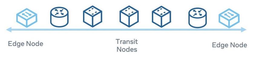
As shown in Figure 4, propagation requires reading the original QoS markings and writing them in the
proper layer (in the example from IP to Ethernet) for further processing.
Figure 4: Reading the Original QoS
Copyright © 2021 Telecom Infra Project, Inc. 21Network as a Service (NaaS) | End-to-End Quality of Service Recommendations for Mobile Networks
Figure 5: QoS propagation in the network and in the node
Propagation is only required when the same packet layer QoS information cannot be used across the
network or in each node itself.
In general, propagation policies are implemented in the form of ACL as described in the classification
policies and in some vendors, propagation is required to guarantee QoS when a packet crosses the fabric.
In this case, propagation policies copy the QoS information from standardized packet fields to non-
standardized fields (i.e., from MPLS, IP/DSCP or b-pits to VoQ Packet descriptors crossing the node’s switch
fabric).
Recommendations
1. Validate propagation policies are properly configured in the nodes.
2. Validate network domains (IP, MPLS, Ethernet) and make sure propagation policies are applied and
are consistent end to end with the QoS schema white traffic is crossing the network.
3. Validate internally the node’s switch fabric is propagating the QoS setting as they traverse the node
(i.e., via VoQ Packet Descriptors tables).
Copyright © 2021 Telecom Infra Project, Inc. 22Network as a Service (NaaS) | End-to-End Quality of Service Recommendations for Mobile Networks
Metering
Rate limiting in the egress port is also known as Metering policies and they can be applied as described for
Policing Policies but in the egress direction.
Usually, metering is required when the node is aggregating traffic and some overbooking control is
required in the egress or to shape the traffic on egress such as a downstream policier will not
unintentionally discard. A similar table as described in Policing policies can be used to rate limit the egress
interface in the nodes.
Recommendations
1. Define overbooking factors for the different layers of the network. Common overbooking factors
are: Access interfaces (1:10), Aggregation interfaces (1:4), Core interfaces (1:1).
2. Validate metering policies are properly configured in the nodes.
3. Verify metering policies are applied to the traffic following the overbooking guidelines depending
on the network layer (Access, Aggregation, Core). As an example, for an interface in the
aggregation layer the sum of the ingress traffic in all the interfaces cannot exceed four times the
bandwidth capacity of the egress interface or capacity.
4. Metering policies must be properly calculated on asymmetrical links (i.e., satellite links).
5. E2E TE tools can be used in the network to calculate available bandwidth in the network.
MPLS/RSVP-TE/CSPF can be used to deploy this type of networks.
Copyright © 2021 Telecom Infra Project, Inc. 23Network as a Service (NaaS) | End-to-End Quality of Service Recommendations for Mobile Networks
Queuing
Before transmission the traffic is stored and processed in queues. Queueing includes complex algorithms or
definitions to empty the queues for transmission including:
1. Queuing schema. A network wide number of queues must be defined across the network in each
interface. Most common queueing schemas to support multimedia traffic include eight or six
queues. Lower quality systems can be implemented with four or two queues.
2. Buffer sizes (Queue Max Capacity). Each queue will support the storage of several frames. This is a
configurable parameter. It can be defined in terms of bytes or frames.
3. Congestion Levels. Other configurable parameter is the level of usage of the queue to activate
congestion management procedure. The following figure shows the congestion level required in a
queue to activate all configured congestion avoidance mechanisms. Once the queue capacity
reaches the maximum, 100% of the packets will be discarded.
Figure 6. Congestion Threshold and Max capacity in a Queue
Copyright © 2021 Telecom Infra Project, Inc. 24Network as a Service (NaaS) | End-to-End Quality of Service Recommendations for Mobile Networks
4. Congestion Management. Once the queue has reached the congestion threshold, enable
congestion management procedures supported in the node. Most common congestion
management procedures include random early discards (RED) and weighted random early discards
(WRED). Congestion management is responsible for packet losses during congestion. However,
there are situations that are not related to congestion that leads to packet losses. This type of
impairment needs to be monitored in other ways. Please check Active Monitoring in this section for
details.
5. Queue Schedulers. Scheduling allows the queue to be emptied is a systematic way. There are
multiple scheduler types such as strict Priority Queueing (PQ), weighted fair queuing (WFQ), round-
robin among others. There are systems in the market that allow combining two scheduler types at
the same time.
6. Hierarchical Schedulers (H-QoS). In complex systems, carrying multiple types of traffic coming from
different interfaces (multiple corporations or Carrier of Carrier applications) with different QoS
settings and being aggregated into a common egress interfaces, the use of hierarchical scheduling
is mandatory. Also known as H-QoS, the hierarchical schedulers allow to process. As showing in the
Figure 7, multiple layers of scheduling can be configured in a node. In diagram, the traffic coming
from two interfaces are managed via a WFQ Scheduler then the traffic is managed in a PQ
scheduler for transmission. Most of the vendors support between three and four levels of H-QoS
for real time multimedia traffic applications.
Copyright © 2021 Telecom Infra Project, Inc. 25Network as a Service (NaaS) | End-to-End Quality of Service Recommendations for Mobile Networks
Figure 7: Hierarchical QoS
For Carrier supporting Carrier (CsC) Networks, such as Mobile Virtual Network Operators (MVNOs) using
different RAN sharing technologies (MORAN, MOCN, GWCN) it is required to use Hierarchical QoS schemas
to allow the coexistence of multiple QoS schemas in the same transport network.
In this way, the QoS settings for each MVNO can be transported over the same network infrastructure
without interfering each other.
Recommendations
1. Select a high number of queues in the interfaces. Eight to six queues are recommended values for a
real time multimedia system
2. It is highly recommended to use longest buffer sizes in the access nodes to support bursty traffic.
3. Congestion thresholds must be defined between 75-90% of queue utilization.
4. Validate node transit delays, in case of excessive delays are identify, troubleshoot the node, and
identify possible causes and fix the issues.
5. Validate node doesn't have packet discards or anomalies introduced during the transit across the
nodes.
Copyright © 2021 Telecom Infra Project, Inc. 26Network as a Service (NaaS) | End-to-End Quality of Service Recommendations for Mobile Networks
6. It is recommended to use a strict priority scheduler for the first two queues (higher priority queues)
and weighted round robin (WRR) for the remaining queues. If this is not possible, select a scheduler
such as WFQ that allows the frame to be transmitted from the first two queues first with weights
avoiding starving some queues during the process.
7. Implement and validate H-QoS configuration
8. Validate consistent setting across the networks and network elements.
9. Validate there is not mismatch in queue priorities (i.e., make sure queue 0 is high priority in all
devices in the end-to-end data path).
Transmission/Reception
This is the process of serializing and deserializing the frame information into the wire. It increases the end-
to-end delay and packet losses on noisy links. High speed interfaces will add less delay to the
communication.
Some vendors included forward error correction (FEC) during transmitting the frames to mitigate noise
environments during the encoding phase, despite FEC will add overheads, the destination node will be able
to decode the original information avoiding retransmission. It is generally used for high-capacity, long-
distance links.
Recommendations
1. Disable auto-negotiation. It is not recommended to use auto-negotiation for the interfaces. It is
always recommended to use the higher speed supported in the interfaces. This will reduce the
serialization delay in the network.
2. MSS selection. Identify the maximum frame size that can be encapsulated in a single frame in the
link layer. Usually, the MTU for ethernet systems is 1500 bytes. So, depending in the encapsulation
and overheads the maximum frame size can be reduced to a lower value, for example for IPsec to
1414 (DES/3DES), 1398 (MD5, SHA-1), 1390 (AH) and so on. Other headers should be included in
the calculation. Not considering the proper value for the frame size should lead to a fragmentation
issues and degradation in the network performance due to reordering and lost packets. For TCP
connections, this value should match the maximum segment size (MSS).
3. Enable FEC on links with support for these features.
4. Monitor transmission delays on the links, track changes and define corrective actions for
unexpected changes.
Copyright © 2021 Telecom Infra Project, Inc. 27Network as a Service (NaaS) | End-to-End Quality of Service Recommendations for Mobile Networks
5. Monitor packet losses on the links, track changes and define corrective actions for unexpected
changes.
6. Validate there are not anomalies in packet processing in the network (i.e., duplicates, malformed,
discards, etc.).
NOTE: Here a sample of an MTU/MSS Calculation for regular IP traffic to be used as
reference:
Column 1 Column 2 Column 3 Column 4 Column 5
Ethernet
IP Header TCP Header Payload FCS
Header
Ethernet MTU
IP MTU
TCP MSS
14 20 20 1460 4
Table 6: MTU/MSS Calculation
Depending on the transport network TCP Header and TCP MSS can change for example when using TCP
header compression or any other advanced features to optimize the overhead.
Copyright © 2021 Telecom Infra Project, Inc. 28Network as a Service (NaaS) | End-to-End Quality of Service Recommendations for Mobile Networks
Active QoS Monitoring
Since traffic is in nature busty, it is hard to perform human based monitoring. Some issues are only seen in
few milliseconds, so they are hard to see and identify. To support network operations there are two major
areas to improve when it comes to QoS monitoring. Those are On-net monitoring and Off-net monitoring.
Monitoring allows system performance parameters such as bandwidth, delay, packet losses, jitter among
other parameters to be tracked during network operation supporting planning and operation team
activities.
Most of the protocols and probes use a client/reflector architecture. The client will send traffic to a
reflector that will return the traffic to the client for reporting as shown in the Figure 8.
Figure 8: Active QoS monitoring
Copyright © 2021 Telecom Infra Project, Inc. 29Network as a Service (NaaS) | End-to-End Quality of Service Recommendations for Mobile Networks
On-net Monitoring
This monitoring technique is also known as NE instrumentation. Here the network and in particular each
network node can send and receive traffic between two Management End Point – (MEPs).
The most common on-net monitoring protocols are:
For L3 networks:
1. TWAMP and
2. RFC2544
3. IP SLAs
For L2 networks:
1. IEEE802.3ah - Ethernet in the first mile.
2. IEEE802.1ag - CFM via loopback (LBM/LBR and linktrace (LTM/LTR)
3. Y.1731 - Ethernet OAM
4. Y.1564/MEF48 - Service activation
Off-net Monitoring
External Probes are also available when on-net monitoring is not 100% available in the network. This
client/server, sender/reflectors are commercially available and can be deployed in strategic points in the
network or in specific sites when some data needs to be collected for further analysis. These devices will
provide the required data and the validation against SLAs
Some vendors in the area are:
• Prosilient Technologies
• Bridge Technologies
• Accedian
Copyright © 2021 Telecom Infra Project, Inc. 30Network as a Service (NaaS) | End-to-End Quality of Service Recommendations for Mobile Networks
Recommendations
1. Keep On-net monitoring probes for the different segments (network domains). Future issues will be
easily identified when these probes are available and active in the network.
2. Deploy/procure Off-net Probes that can be used to monitor particular areas of the network.
General Recommendations on limited support for QoS
Some networks have very limited QoS features hence it is difficult to implement all the recommendations
or some of them. In most of the cases, there are some few mitigation actions that can be observed to
increase the network performance.
Here a list of the main recommendations:
1. Deep buffers. Some switch routers allow the operator to configure longer queues to improve the
node capacity to tolerate burst traffic. Deep buffers will allow the traffic to stay in a queue for a
longer time i.e., 100 msec or more until it is ready for transmission. Deep buffers require devices
with high-capacity memory onboard.
2. Smaller MTU. To avoid long waiting times in the queues, it recommended to uses shorter MTUs in
the interfaces. In this case voice traffic doesn’t need to wait to transmit long data frames. This is
applicable in systems with small numbers of queues supported in the interfaces. To optimize the
network UE can also be configured with smaller MTUs so there is no possibility for fragmentation in
the transport network. In some cases, it can be counterproductive since this can lead to
fragmentation and reordering packets that can extra overhead and delays.
3. Bandwidth over-provisioning. Increase the bandwidth to a value that delays the network
congestion to happen is also a common practice when limited QoS support is present in the
network. But this can unnecessarily increase the cost of the network operation.
Copyright © 2021 Telecom Infra Project, Inc. 31Network as a Service (NaaS) | End-to-End Quality of Service Recommendations for Mobile Networks
4. Enable A-bis and Iu-CS optimization features. Some vendors can provide local voice switching for
2G/3G network avoiding traffic tromboning and double dipping in the bandwidth utilization. These
technologies are commonly used in satellite backhaul applications and are available in the CSR or
integrated in the BTS or Node B. By enabling these features, the node can locally connect/switch
voice traffic without using the satellite backhaul capacity.
Conclusions
Though End-to-End QoS enforcement can be a complex task it is necessary to have. Lack of consistency in
the QoS service parameters can lead to unpredictable network performance, failure to meet application
requirements, and bad quality of experience.
The End-to-End QoS validation comprises the following major activities:
Passive Validation
1. Data fill Analysis. By comparing the QoS setting (Classification tables, Marking tables, propagation
tables, Queuing schemas) in the configuration files for the devices, deviations can be identified.
This can be a manual activity by selecting few nodes (i.e., where QoS issues have been reported) or
via automation scripts when network size is considerable (i.e., from 10s to 1000s network
elements).
Active Validation
1. On-net QoS probes. Most of the vendors provide support in their OSs to deploy QoS probes with
multiple standardized protocols. This can identify misalignments and detect QoS issues in the
network.
2. Off-net QoS probes. External probes can be deployed in strategic points in the network or in ad-
hoc sites to identify and monitor network QoS.
This analysis will identify the sites and issues present in the network and take the corresponding corrective
actions.
Copyright © 2021 Telecom Infra Project, Inc. 32Network as a Service (NaaS) | End-to-End Quality of Service Recommendations for Mobile Networks
Glossary
A E
AAA – Authentication, Authorization and EBS – Excess Burst Size
Accounting EIR – Excess Information Rate
APN – Access Point Name eNodeB – Evolved Node B in 3GGP 4G
Apps – Applications architectures
ACL – Access Control List EPC – Evolved Packet Core
EVPN – Ethernet Virtual Private Network
B EXP – Experimental Bits in MPLS Label
BA – Behavior Aggregate
BGP – Border Gateway Protocol F
BTS – Base Transceiver Station FACH – Forward Access Channel
BW – Bandwidth FCS – Frame Check Sequence
FEC – Forward Error Correction
C
CBH - Catalyzer Bed Heaters G
CBS – Committed burst size 3GPP – 3rd Generation Partnership Project
CP – Control Plane GBR – Guarantee Bit Rate Service
CIR – Committed information Rate GGSN – Gateway GRPS Support Node
CoS – Class of service GPRS – General Packet Radio Service
CS – Circuit Switching GRE – Generic Routing Encapsulation
CSC – Carrier Supporting Carrier GTP – GPRS Tunneling Protocol
CSR – Cell Site Router GWCN – Gateway Core Network
CSG – Cell Site Gateway
CSPF – Constrained Shortest path First H
H-QoS – Hierarchical Quality of service
D
DEI – Discard Eligibility Indicator bit I
DHCP – Dynamic Host Configuration Protocol IETF – Internet Engineering Task Force
DP – Data Plane IMS – IP Multimedia Subsystem
DSCP – Diff Service Code Point Field/Architecture IP – Internet Protocol
IpT – Internet Para Todos in Peru
Copyright © 2021 Telecom Infra Project, Inc. 33Network as a Service (NaaS) | End-to-End Quality of Service Recommendations for Mobile Networks
Ipsec – Internet Protocol Security O&M – Operations and Maintenance
IS-IS – Intermediate System to Intermediate OML – Organizational and Maintenance Link
System Protocol
P
K PCH – Paging Channel
Kbps – Kilobits per second PCP – Priority Code Point
KB – Kilo bytes PCRF – Policy Control and Resource Function
P Router – Provider Router in a MPLS
L architecture (Core Node)
LDAP – Lightweight Directory Access Protocol PE Router – Provide Edge Router in a MPLS
LBM – Loopback Messages architecture (Edge Node)
LBR – Loopback Replay Messages P-GW – Packet Gateway
LTM – Link Trace Messages PHP – Per Hop Behavior
LTR – Link Trace Reply messages Prio – Priority
LTE – Long Term Evolution (3GPP 4G PTP – Precision Time Protocol
Architecture) PQ – Priority Queueing
M Q
MAC – Media Access Control QCI – QoS Class Identifier
MEP – Management End Point QoS – Quality of Service
MEF – Metro Ethernet Forum QoE – Quality of Experience
MetroE – Metro Ethernet Network
MME- Mobility Management Entity R
MOCN – Multi Operator Core Network RAN – Radio Access Networks (3GPP 2G, 3G, 4G,
MORAN – Multi Operator Radio Access Network 5G, IEEE Wi-Fi)
MPLS – Multiprotocol Label Switching RACH – Random Access Channel
Msec – Milliseconds RBS – Radio Base Station
MSS – Maximum Segment Size RED – Random Early Discard
MTU – Maximum Transmit Unit RFC – Request for Comments
N RTN – Return Channel, Retro Television Network
NTP – Network Time Protocol RTC – Real time communications
RCS – Rich Communication System
O RSL – Radio Signaling Link
OSPF – Open Shortest Path First Protocol RSVP – TE – Resource Reservation Protocol –
Copyright © 2021 Telecom Infra Project, Inc. 34Network as a Service (NaaS) | End-to-End Quality of Service Recommendations for Mobile Networks
Traffic Engineering
V
S VoD – Video on Demand
SIP – Session Initiation Protocol VoIP – Voice Over IP Protocol
SIP-I – Session Initiation Protocol - Interworking VoQ – Virtual Output Queueing
S-GW – Serving Gateway VLAN – Virtual Local Area Network
SGSN – Serving GRPS Support Node VPLS – Virtual Private Line Service
SFTP – Secure File Transfer Protocol VSAT – Very Small Aperture Terminal
SLA – Service Level Agreement
Sync – Synchronization W
Wi-Fi – Wireless Fidelity
T WFQ – Weighted Fair Queuing
TCP – Transmission Control Protocol WRED – Weighted Random Early Discard
3PP – Third Party Product WRR – Weighted Round Robin
U X
UE – User Equipment X2 – X2 3GPP Interface
UDP – User Datagram Protocol
Copyright © 2021 Telecom Infra Project, Inc. 35Network as a Service (NaaS) | End-to-End Quality of Service Recommendations for Mobile Networks
TIP Document License
By using and/or copying this document, or the TIP document from which this statement is linked, you (the
licensee) agree that you have read, understood, and will comply with the following terms and conditions:
Permission to copy, display and distribute the contents of this document, or the TIP document from which
this statement is linked, in any medium for any purpose and without fee or royalty is hereby granted under
the copyrights of TIP and its Contributors, provided that you include the following on ALL copies of the
document, or portions thereof, that you use:
1. A link or URL to the original TIP document.
2. The pre-existing copyright notice of the original author, or if it doesn't exist, a notice (hypertext is
preferred, but a textual representation is permitted) of the form: "Copyright © , TIP and
its Contributors. All rights Reserved"
3. When space permits, inclusion of the full text of this License should be provided. We request that
authorship attribution be provided in any software, documents, or other items or products that you
create pursuant to the implementation of the contents of this document, or any portion thereof.
No right to create modifications or derivatives of TIP documents is granted pursuant to this License. except
as follows: To facilitate implementation of software or specifications that may be the subject of this
document, anyone may prepare and distribute derivative works and portions of this document in such
implementations, in supporting materials accompanying the implementations, PROVIDED that all such
materials include the copyright notice above and this License. HOWEVER, the publication of derivative
works of this document for any other purpose is expressly prohibited.
For the avoidance of doubt, Software and Specifications, as those terms are defined in TIP's Organizational
Documents (which may be accessed at
https://telecominfraproject.com/organizational-documents/), and components thereof incorporated into
Copyright © 2021 Telecom Infra Project, Inc. 36Network as a Service (NaaS) | End-to-End Quality of Service Recommendations for Mobile Networks
the Document are licensed in accordance with the applicable Organizational Document(s).
Disclaimers
THIS DOCUMENT IS PROVIDED "AS IS," AND TIP MAKES NO REPRESENTATIONS OR WARRANTIES, EXPRESS
OR IMPLIED, INCLUDING, BUT NOT LIMITED TO, WARRANTIES OF MERCHANTABILITY, FITNESS FOR A
PARTICULAR PURPOSE, NON-INFRINGEMENT, OR TITLE; THAT THE CONTENTS OF THE DOCUMENT ARE
SUITABLE FOR ANY PURPOSE; NOR THAT THE IMPLEMENTATION OF SUCH CONTENTS WILL NOT INFRINGE
ANY THIRD PARTY PATENTS, COPYRIGHTS, TRADEMARKS OR OTHER RIGHTS.
TIP WILL NOT BE LIABLE FOR ANY DIRECT, INDIRECT, SPECIAL OR CONSEQUENTIAL DAMAGES ARISING OUT
OF ANY USE OF THE DOCUMENT OR THE PERFORMANCE OR IMPLEMENTATION OF THE CONTENTS
THEREOF.
The name or trademarks of TIP may NOT be used in advertising or publicity pertaining to this document or
its contents without specific, written prior permission. Title to copyright in this document will at all times
remain with TIP and its Contributors.
This TIP Document License is based, with permission from the W3C, on the W3C Document License which
may be found at https://www.w3.org/Consortium/Legal/2015/doc-license.html.
Copyright © 2021 Telecom Infra Project, Inc. 37Network as a Service (NaaS) | End-to-End Quality of Service Recommendations for Mobile Networks
Copyright © 2021 Telecom Infra Project, Inc. A TIP Participant, as that term is defined in
TIP’s Bylaws, may make copies, distribute, display or publish this Specification solely as
needed for the Participant to produce conformant implementations of the Specification,
alone or in combination with its authorized partners. All other rights reserved.
The Telecom Infra Project logo is a trademark of Telecom Infra Project, Inc. (the “Project”) in
the United States or other countries and is registered in one or more countries. Removal of
any of the notices or disclaimers contained in this document is strictly prohibited.
Copyright © 2021 Telecom Infra Project, Inc. 38You can also read