Masoneilan SVIFF Digital Positioner - Quick Start Guide (Rev. F) - Baker Hughes DAM
←
→
Page content transcription
If your browser does not render page correctly, please read the page content below
Masoneilan™
SVI™FF Digital Positioner
Quick Start Guide (Rev. F)

Baker Hughes Data Classification: Public
About this Guide
This Quick Start Guide applies to the SVI FF instrument and supported software:
with Firmware version 1.0.0.1 or higher
with ValVue™ version 3.0
with handheld communicator with DD published for SVI FF
All information contained herein is believed to be accurate at the time of publication and is subject to
change without notice.
The information contained in this manual, in whole or part, shall not be transcribed or copied without
Baker Hughes’ written permission.
In no case does this manual guarantee the merchantability of the positioner or the software or its
adaptability to a specific client needs.
Please report any errors or questions about the information in this manual to your local supplier or
visit valves.bakerhughes.com. .
DISCLAIMER
THESE INSTRUCTIONS PROVIDE THE CUSTOMER/OPERATOR WITH IMPORTANT PROJECT-
SPECIFIC REFERENCE INFORMATION IN ADDITION TO THE CUSTOMER/OPERATOR’S
NORMAL OPERATION AND MAINTENANCE PROCEDURES. SINCE OPERATION AND
MAINTENANCE PHILOSOPHIES VARY, BAKER HUGHES COMPANY (AND ITS SUBSIDIARIES
AND AFFILIATES) DOES NOT ATTEMPT TO DICTATE SPECIFIC PROCEDURES, BUT TO
PROVIDE BASIC LIMITATIONS AND REQUIREMENTS CREATED BY THE TYPE OF EQUIPMENT
PROVIDED.
THESE INSTRUCTIONS ASSUME THAT OPERATORS ALREADY HAVE A GENERAL
UNDERSTANDING OF THE REQUIREMENTS FOR SAFE OPERATION OF MECHANICAL AND
ELECTRICAL EQUIPMENT IN POTENTIALLY HAZARDOUS ENVIRONMENTS. THEREFORE,
THESE INSTRUCTIONS SHOULD BE INTERPRETED AND APPLIED IN CONJUNCTION WITH
THE SAFETY RULES AND REGULATIONS APPLICABLE AT THE SITE AND THE PARTICULAR
REQUIREMENTS FOR OPERATION OF OTHER EQUIPMENT AT THE SITE.
THESE INSTRUCTIONS DO NOT PURPORT TO COVER ALL DETAILS OR VARIATIONS IN
EQUIPMENT NOR TO PROVIDE FOR EVERY POSSIBLE CONTINGENCY TO BE MET IN
CONNECTION WITH INSTALLATION, OPERATION OR MAINTENANCE. SHOULD FURTHER
INFORMATION BE DESIRED OR SHOULD PARTICULAR PROBLEMS ARISE WHICH ARE NOT
COVERED SUFFICIENTLY FOR THE CUSTOMER/OPERATOR’S PURPOSES THE MATTER
SHOULD BE REFERRED TO BAKER HUGHES.
THE RIGHTS, OBLIGATIONS AND LIABILITIES OF BAKER HUGHES AND THE CUSTOMER/
OPERATOR ARE STRICTLY LIMITED TO THOSE EXPRESSLY PROVIDED IN THE CONTRACT
RELATING TO THE SUPPLY OF THE EQUIPMENT. NO ADDITIONAL REPRESENTATIONS OR
WARRANTIES BY BAKER HUGHES REGARDING THE EQUIPMENT OR ITS USE ARE GIVEN
OR IMPLIED BY THE ISSUE OF THESE INSTRUCTIONS.
THESE INSTRUCTIONS ARE FURNISHED TO THE CUSTOMER/OPERATOR SOLELY TO ASSIST
IN THE INSTALLATION, TESTING, OPERATION, AND/OR MAINTENANCE OF THE EQUIPMENT
DESCRIBED. THIS DOCUMENT SHALL NOT BE REPRODUCED IN WHOLE OR IN PART
WITHOUT THE WRITTEN APPROVAL OF BAKER HUGHES.
Copyright
All information contained herein is believed to be accurate at the time of publication and is subject to
change without notice.
Copyright 2021 by Baker Hughes Company. All rights reserved. PN 720023977-888- 0000 Rev. F.
2 | © 2021 Baker Hughes Company. All rights reserved.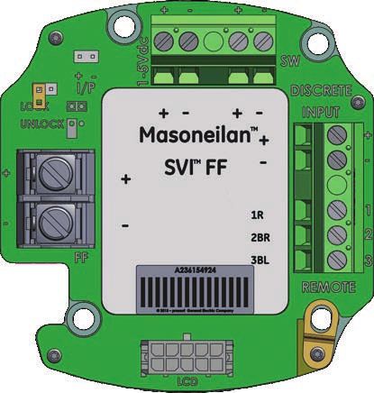
© 2021 Baker Hughes Company. All rights reserved. Masoneilan SVI FF Digital Positioner Quick Start Guide | 3
Document Changes
    Version/Date                        Changes

 B/12-14           Updated headers and footers.
                   Made a few changes to Quick Start sectionChanged ES-776
                   to Rev J.

 C/02-15           Changed ES-776 to Rev. K and to Declaration ofConformity

 D/03-17           Changed ES-776 to Rev. L.

 E/02-20           Changed ES-776 to Rev. M. Rebranded to
                   Baker Hughes formats.Added Product Num-
                   bering section.
                   Added Determining Device Descriptor and FirmwareVersions
                   AP Label section.
                   Updated Mounting the SVI FF on Rotary Valvessection.

 F/07-21           ES-776 instructions removed.

4 | 						                                 © 2021 Baker Hughes Company. All rights reserved.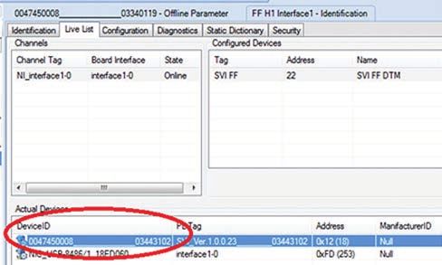
Table of Contents

About this Guide....................................................................................... 2

Document Changes.................................................................................. 4

Safety Information.................................................................................... 6
      Safety Symbols............................................................................................... 6

SVI FF Product Safety.............................................................................. 7
          General installation, maintenance or replacement......................................................... 7
          Intrinsically Safe Installation........................................................................................... 7

Masoneilan Help Contacts....................................................................... 8

Product Numbering.................................................................................. 9

Device Descriptor and Firmware ........................................................... 9

Installation and Set Up........................................................................... 12

Pushbuttons and Local Display............................................................ 13

Mounting the SVI FF on Rotary Valves................................................. 14

Mounting the SVI FF on Reciprocating Valves.................................... 15

Wiring the SVI FF.................................................................................... 16

FF Environment Minimum Settings...................................................... 17
          Step 1: Set Air Action................................................................................................... 17
          Step 2: Set Control Tuning........................................................................................... 17
          Step 3: Set Characterization Type................................................................................ 17
          Step 4: Enter a Device Address and Device Tag......................................................... 17
          Step 5: Run Find Stops and then run Autotune............................................................ 17

Example Configuration.......................................................................... 18
          Step 1: Install the Positioner on the Valve.................................................................... 18
          Step 2: Set Tag and Address........................................................................................ 18
          Step 3: Basic Configuration.......................................................................................... 19
          Step 4: Run Find Stops METHOD............................................................................... 20
          Step 5: Run Auto Tune METHOD................................................................................ 20

Downloads.............................................................................................. 20

Hazardous Location Installation........................................................... 21

  © 2021 Baker Hughes Company. All rights reserved.               Masoneilan SVI FF Digital Positioner Quick Start Guide | 5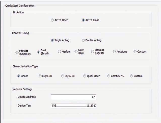
Safety Information
This section provides safety information and defines the documentation symbols.

Safety Symbols
SVI FF instructions contain warnings, cautions and notes, where necessary, to alert you to
safety related or other important information. Read the instructions carefully before installing
and maintaining your instrument. Total compliance with all WARNING, and CAUTION notices is
required for safe operation.

           WARNING
                               Indicates a potentially hazardous situation,
                               which if not avoided could result in serious
                               injury or death.

           CAUTION             Indicates a potentially hazardous situation,
                               which if not avoided could result in
                               instrument or property damage, or data loss.

              NOTE
                               Indicates important facts and conditions.

6 | 						                                             © 2021 Baker Hughes Company. All rights reserved.
SVI FF Product Safety
For SVI FF positioners intended for use with industrial compressed air:
Ensure that an adequate pressure relief provision is installed when the application of system
supply pressure could cause peripheral equipment to malfunction. Installation must be in
accordance with local and national compressed air and instrumentation codes.
General installation, maintenance or replacement
• Products must be installed in compliance with all local and national codes and standards
by qualified personnel using safe site work practices. Personal Protective Equipment
(PPE) must be used per safe site work practices.
• Ensure proper use of fall protection when working at heights, per safe site work
practices. Use appropriate safety equipment and practices to prevent the dropping of
tools or equipment during installation.
• Under normal operation, compressed supply gas is vented from the SVI FF to the
surrounding area, and may require additional precautions or specialized installations.
Intrinsically Safe Installation
Products certified as explosion proof or flame proof equipment or for use in intrinsically
safe installations MUST BE:
• Installed, put into service, used and maintained in compliance with national and local
regulations and in accordance with the recommendations contained in the relevant
standards concerning those environments.
• Used only in situations that comply with the certification conditions shown in this
document and after verification of their compatibility with the zone of intended use and
the permitted maximum ambient temperature.
• Installed, put into service and maintained by qualified and competent professionals who
have undergone suitable training for instrumentation used in such areas.
© 2021 Baker Hughes Company. All rights reserved. Masoneilan SVI FF Digital Positioner Quick Start Guide | 7WARNING Before using these products with fluids/compressed gases other than
air or for non-industrial applications,consult the factory. This product
is not intended for use in life support systems.
WARNING Under certain operating conditions, the use of damaged instruments
could cause a degradation of the performance of the system which
may lead to personal injury or death.
WARNING Installation in poorly ventilated confined areas, with any potential
of gases other than oxygen being present, can lead to a risk of
personnel asphyxiation.
Use only genuine replacement parts which are provided by themanufacturer, to guarantee
that the products comply with the essential safety requirements of the European Directives.
Changes to specifications, structure, and components usedmay not lead to the revision
of this manual unless such changes affect the function and performance of the product.
Masoneilan Help Contacts
• Email: svisupport@bakerhughes.com
• Phone: 888-SVI-LINE (888-784-5463)
8 | © 2021 Baker Hughes Company. All rights reserved.Product Numbering
Refer to Masoneilan SVI FF Safe Use instructions ES-776 available in:
valves.bakerhughes.com/resource-center
Determining Device Descriptor and Firmware
Versions AP Label
It is useful to track the version of the Device Descriptor (DD) and firmware version in use on
your DCS and positioner respectively. This is of value in troubleshooting system issues that
can arise when initially installing and later upgrading Masoneilan and non-Masoneilan system
components. There are several different ways to access the required information.
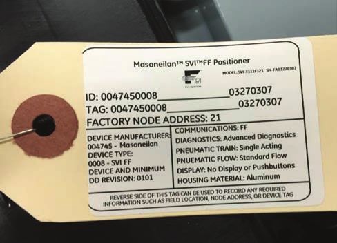
Figure 1 shows the unit tag that comes attached to the unit.
Figure 1 - Unit Tag
© 2021 Baker Hughes Company. All rights reserved. Masoneilan SVI FF Digital Positioner Quick Start Guide | 9The tag lists the following items:
ID: Unique factory-set identifier for the Tag: User-defined. This can be
device. changed for the specific application.
Factory Node Address: Lists the Device Manufacturer: The six digits
factory-set field bus node address. comprise the first part of the ID and
Tag. Used to identify the DD.
Device Type: A four digit code. Device and Minimum DD Revision:
Represents the original firmware
revision flashed during manufacture.
This DD may have been upgraded
since installation.
Communications: Lists the protocol in Diagnostics: Lists the level of
use. diagnostics with which the device
was shipped. This may have been
upgraded since installation.
Pneumatic Train: Single Acting or Pneumatic Flow: Standard Flow or
Double Acting. High Flow.
Display: Indicates whether the LED Housing: Aluminum only.
display and pushbuttons are installed.
The actual device ID in this case is constructed according to the following
formula:
004745 – which is the manufacturer identifier for Masoneilan
0008 – which is the device type for SVI FF positioner
______________ - 14 underscore characters
XXXXXXXX – the eight number string for the device part number as shown in the
picture below (first two letters are ignored)
From the Live List information presented in the DCS or in the Communication DTM
(Figure 2).
Figure 2 - Device ID: Live List
10 | © 2021 Baker Hughes Company. All rights reserved. From the DTM, when open in connected mode (note: some hosts may not support this
feature):
Figure 3 - Device ID: DTM
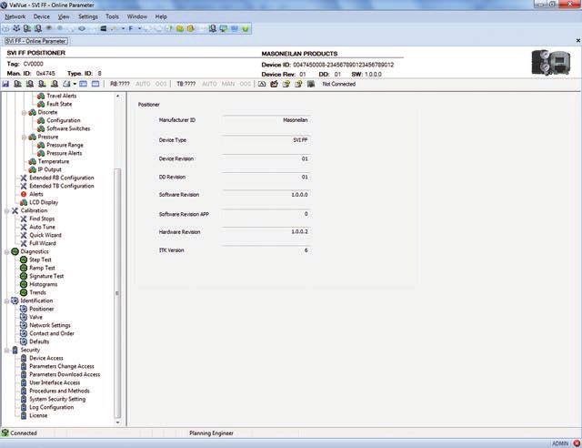
Firmware versions can also be viewed using the:
SVI FF DTM on the Positioner tab. The firmware revision is Software Revision
(Figure 4). Where the first digit, here 1, represents the DD Revision.
Figure 4 - Positioner Tab
By creating/printing the SVI FF Configuration Report by:
1. Selecting View > Network View > Topology Pane.
2. Selecting the positioner, right-clicking and selecting Additional Functions >
Report.
Handheld by selecting Online > SVI FF Device > Resource Block > Device >
Identification.
© 2021 Baker Hughes Company. All rights reserved. Masoneilan SVI FF Digital Positioner Quick Start Guide | 11Installation and Set Up
The steps necessary to complete the SVI FF installation and software setup are outlined in
Table 1.
Table 1 - SVI FF Installation Steps
Step
Procedure
No.
1 Attach mounting bracket to the actuator.
2 Install the SVI FF magnetic assembly (rotary valves only).
3 Assemble the SVI FF on the bracket that is mounted to the valve actuator.
4 Connect the pneumatic tubing to the SVI FF.
5 Connect the air supply to the SVI FF.
6 Connect the positioner to the H1 segment by installing the SVI FF wiring.
Configure/calibrate using ValVue, the SVI FF DTM or a handheld using the DD.
7
See Example Configuration on page 18 for a general example.
WARNING Failure to adhere to the requirements listed may
cause loss of life and property.
Before installing, using, or carrying out any
maintenance tasks associated with this
instrument, READ ALL THE INSTRUCTIONS
CAREFULLY.
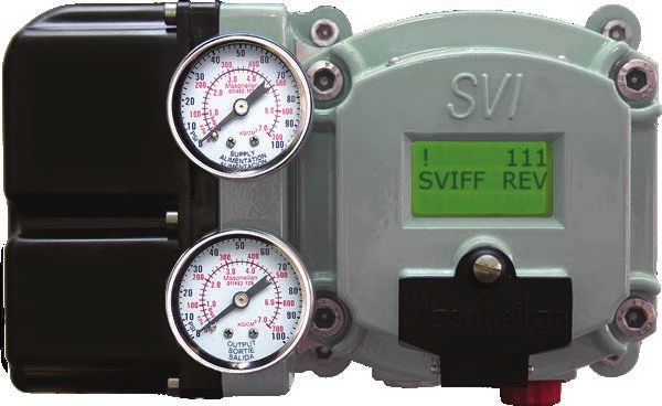
12 | © 2021 Baker Hughes Company. All rights reserved.Pushbuttons and Local Display
Pushbuttons
The local pushbuttons are located behind a hinged cover, directly below the display window. To
open the cover loosen the screw and swing the cover down. Always re-fasten the cover after
use to protect the pushbuttons from environmental contamination. The pushbuttons perform the
following:
Left Button - Marked with *, permits you to select or accept the value or parameter
option currently displayed.
Middle Button - Marked –, permits you to move back through the menu structure to
the previous item in the menu or decrement the value currently shown in the digital
display. When used to decrease a displayed value, holding the button down causes
the value to decrease at a faster rate.
Right Button - Marked +, permits you to move forward through the menu structure
to the next item in the menu, or to increment the value currently shown in the digital
display. When used to increase a displayed value, holding this button down causes
the value to increase at a faster rate.
CAUTION The display is limited to values between 0 and
100. Therefore, the display may show a value for
the actual setpoint that is not valid if the setpoint
is above 100 or below 0.
NOTE When an exclamation point (!) appears in the SVI FF
display window, it indicates that there is instrument status
available.
© 2021 Baker Hughes Company. All rights reserved. Masoneilan SVI FF Digital Positioner Quick Start Guide | 13Mounting the SVI FF on Rotary Valves
Travel Sensor Alignment
Table 2 shows the general guidelines for travel sensor alignment. Review the table prior to
installing the SVI FF on a rotary valve actuator for proper alignment of the magnet. Alignment is
required for proper Hall sensor operation.
Table 2 - Travel Sensor Alignment
Stroke Direction
Rotary (An accumulated value Sensor
Magnet Valve Counts
Mounting of 100% travel = 1
stroke. The travel does Orientation Position
System (TB: RAW_POSITION)
not need to occur in one
movement):
Rotary 60° Rotation Full Open -8000 +/- 1500
Clockwise with or or
increasing setpoint Full Closed +8000 +/- 1500
(-45°)
>60° Rotation Full Open -8000 +/- 1500
Counter Clockwise
or or
rotation with increasing
setpoint Full Closed +8000 +/- 1500
(+45°)
General Rule Any amount of 50%
for other rotation Clockwise or Travel 0 +/- 1000
configurations counterclockwise (Mid-Stroke)
(0°)
14 | © 2021 Baker Hughes Company. All rights reserved.Mounting the SVI FF on Reciprocating Valves
Table 3 - Reciprocating Valve Mounting Hole and Turnbuckle Length
Actuator
Mounting Lever Turnbuckle
Size Stroke
Hole Hole Length
Masoneilan
0.5 - 0.8” 1.25”
6 and 10 A A
(12.7 - 20.32 mm) (31.75 mm)
0.5 - 0.8” 1.25”
10 A A
(12.7 - 20.32 mm) (31.75 mm)
>0.8 – 1.5” 1.25”
10 B B
(20.32 - 41.5 mm) (31.75 mm)
0.5 - 0.8” 2.90”
16 B A
(12.7 - 20.32 mm) (73.66 mm)
>0.8 – 1.5” 2.90”
16 C B
(20.32 - 41.5 mm) (73.66 mm)
>1.5 – 2.5” 2.90”
16 D C
(41.5 - 63.5 mm) (73.66 mm)
0.5 - 0.8” 5.25”
23 B A
(12.7 - 20.32 mm) (133.35 mm)
>0.8 – 1.5” 5.25”
23 C B
(20.32 - 41.5 mm) (133.35 mm)
>1.5 – 2.5” 5.25”
23 D C
(41.5 - 63.5 mm) (133.35 mm)
© 2021 Baker Hughes Company. All rights reserved. Masoneilan SVI FF Digital Positioner Quick Start Guide | 15Wiring the SVI FF
AI PV 1-5 VDC
(Not used in this release)
I/P Connector Discrete Out
Configuration Lock
Jumper
Discrete Input
(Activated
9 - 32 V Foundation using SMARTs
Fieldbus Input Assistant)
Signal (polarity
independent) Remote Position
Sensor Input
Shield
(on FF unit housing)
Display
Figure 5 - Connections to Electronics Module (via Terminal Board)
16 | © 2021 Baker Hughes Company. All rights reserved.FF Environment Minimum Settings
The general steps necessary to complete the SVI FF configuration and software setup are
outlined in Figure 6.
Step 1: Set Air Action
Step 2: Set Control Tuning by choosing
Single or Double Acting and setting tuning
type. Autotune is recommended, Custom
Requires entering your own values.
Step 3: Set Characterization Type.
Custom requires entering your own values.
Step 4: Enter a Device Address and Device Tag.
Step 5: Run Find Stops and then run Autotune.
Figure 6 - Quick Start Configuration
© 2021 Baker Hughes Company. All rights reserved. Masoneilan SVI FF Digital Positioner Quick Start Guide | 17Example Configuration
Step 1: Install the Positioner on the Valve
See Installation and Set Up on page 12.
Step 2: Set Tag and Address
Using NI Configurator:
1. Import DD/CFF files.
CAUTION Do not navigate to the NI DD folder and copy the
DD file onto itself.
2. Right-click on the device, select Set Tag, follow the prompts to enter a
Tag.
3. Click Set.
CAUTION Do not deactivate the Set to OOS mode check-
box. The block must be in OOS to change the
Tag.
4. Right-click on the device, select Set Address, follow the prompts to enter
an Address.
CAUTION If the device is at the temporary address range
(248 (0xF8)- 251 (OxFB)), you must set the
address outside of that range.
5. Click Set.
CAUTION Do not deactivate the Set to OOS mode check-
box. The block must be in OOS to change the
Address.
18 | © 2021 Baker Hughes Company. All rights reserved.Step 3: Basic Configuration
This section serves as an example where the AO block and TB block are configured. However,
there are a number of combinations that can be configured. This discussion is valid if the
positioner is controlled by the AO block.
1. For the Transducer block set:
ACTUATOR_3.ACT_FAIL_ACTION_1 = either 1. Valve Closed (most
common) or 2. Valve Open
ACCESSORY.REMOTE_SENSOR = 0, if remote sensor is not in use (internal
Hall sensor is used)
ACTIVATE_CONTROL_SET to one of:
0: Activate 1: Activate 2: Activate
Custom Control Set Control Set 1 Control Set 2
(required for Autotune (Slowest)
as well - most common)
3: Activate 4: Activate 5: Activate
Control Set 3 Control Set 4 Control Set 5
(Fastest)
6: Activate 7: Activate
Control Set 6 Control Set 7
(Double Acting - Slow) (Double Acting- Fast)
CHAR_SELECTION.TYPE to one of:
0. Linear (most 1. Equal 2. Equal
common) Percentage (30:1) Percentage
(50:1)
3. Quick Open (reversal 4. Custom 5. Camflex™
from Equal Percentage Percentage
(50:1))
See Transducer Block Parameters in the SVI FF instruction manual for further
settings.
2. For the AO block review/set as below:
PV_SCALE.UNIT INDEX XD_SCALE.UNIT CHANNEL =
=% INDEX = % Position
SHED_OPT =
NORMAL SHED
NORMAL RETURN
© 2021 Baker Hughes Company. All rights reserved. Masoneilan SVI FF Digital Positioner Quick Start Guide | 19Step 4: Run Find Stops METHOD Use a configuration tool (DD, SVI FF local pushbuttons or software) to run METHOD. Step 5: Run Auto Tune METHOD Use a configuration tool (DD, SVI FF local pushbuttons or software) to run METHOD. Downloads To download the complete user manual, DD, SVI FF Advanced DTM and the ValVue Suite trial program, visit: https://valves.bakerhughes.com/resource-center. 20 | © 2021 Baker Hughes Company. All rights reserved.
Hazardous Location Installation
              WARNING             Refer to ES-776 Safe Use Instructions for
                                  installing Masoneilan SVI FF in areas where
                                  there is a potential risk for explosive gas
                                  atmosphere or inflammable dust.

                                  ES-776 instructions are available in several
                                  languages on: valves.bakerhughes.com/
                                  resource-cente

© 2021 Baker Hughes Company. All rights reserved.   Masoneilan SVI FF Digital Positioner Quick Start Guide | 21
Notes: 22 | © 2021 Baker Hughes Company. All rights reserved.
Notes:

© 2021 Baker Hughes Company. All rights reserved.   Masoneilan SVI FF Digital Positioner Quick Start Guide | 23
Direct Sales Office Locations
     Australia                                               Italy                                 Singapore
     Brisbane                                                Phone: +39-081-7892-111               Phone: +65-6861-6100
     Phone: +61-7-3001-4319
                                                             Japan                                 South Africa
     Perth
                                                             Tokyo                                 Phone: +27-83-387-9300
     Phone: +61-8-6595-7018
                                                             Phone: +81-03-6871-9008
     Melbourne                                                                                     South & Central
     Phone: +61-3-8807-6002                                  Korea                                 America and the Caribbean
                                                             Phone: +82-2-2274-0748                Phone: +55-12-2134-1201
     Brazil
     Phone: +55-19-2104-6900                                 Malaysia                              Spain
                                                             Phone: +60-3-2161-03228               Phone: +34-935-877-605
     China
     Phone: +86-10-5738-8888                                 Mexico                                United Arab Emirates
                                                             Phone: +52-55-3640-5060               Phone: +971-4-8991-777
     France
     Courbevoie                                              Russia                                United Kingdom
     Phone: +33-1-4904-9000                                  Veliky Novgorod                       Phone: +44-7919-382-156
                                                             Phone: +7-8162-55-7898
     India                                                                                         United States
                                                             Moscow
     Mumbai                                                                                        Houston, Texas
                                                             Phone: +7-495-585-1276
     Phone: +91-22-8354790                                                                         Phone: +1-713-966-3600
                                                             Saudi Arabia
     New Delhi
                                                             Phone: +966-3-341-0278
     Phone: +91-11-2-6164175

               Find the nearest local Channel Partner in your area:
                        valves.bakerhughes.com/contact-us

                   Tech Field Support & Warranty:
                                              Phone: +1-866-827-5378
                                          valvesupport@bakerhughes.com

                                              valves.bakerhughes.com

Copyright 2021 Baker Hughes Company. All rights reserved. Baker Hughes provides this
information on an “as is” basis for general information purposes. Baker Hughes does not
make any representation as to the accuracy or completeness of the information and makes
no warranties of any kind, specific, implied or oral, to the fullest extent permissible by
law, including those of merchantability and fitness for a particular purpose or use. Baker
Hughes hereby disclaims any and all liability for any direct, indirect, consequential or special
damages, claims for lost profits, or third party claims arising from the use of the information,
whether a claim is asserted in contract, tort, or otherwise. Baker Hughes reserves the right
to make changes in specifications and features shown herein, or discontinue the product
described at any time without notice or obligation. Contact your Baker Hughes representative
for the most current information. The Baker Hughes logo, Masoneilan, SVI, Camflex and
ValVue are trademarks of Baker Hughes Company. Other company names and product
names used in this document are the registered trademarks or trademarks of their respective
owners.

BHMN-SVI FF-QSG-31030F-0821                     08/2021                                                        bakerhughes.com
You can also read