Master Plan Application for Major Land Development Project 3.16 MW DC Ground Mount Solar PV Development
←
→
Page content transcription
If your browser does not render page correctly, please read the page content below
Master Plan Application for
Major Land Development Project
3.16 MW DC Ground Mount Solar PV Development
West Main Road, Map 44, Lot 15 (Site 1)
Portsmouth, RI
Zoning: Light Industrial and Commercial
February 22, 2021
DESIGN REVIEW BOARD SUBMITTAL
PROJECT NARRATIVE
This submittal is for a proposed 3.16 MW DC ground mounted solar photovoltaic (PV) project located on
West Main Road (Map 44, Lot 15) in the Town of Portsmouth, Rhode Island. Per Chapter 405, Article V. of
the Town’s Zoning Ordinance, approval of a large solar energy system project in the light-industrial or
commercial zoning district, requires a Major Land Development Review approved by the Planning Board,
which includes prior review by the Design Review Board. The project has been designed to comply with
the Town’s zoning and development regulations, including the Solar Energy Systems Zoning Ordinance
Amendments, Ordinance # 2020-05-11B. A Pre-application/Informal Concept Plan for this proposed
development was previously presented to the Planning Board at the January 13, 2021 meeting and
comments received at that meeting have been incorporated into this submittal, as applicable.
Project Description:
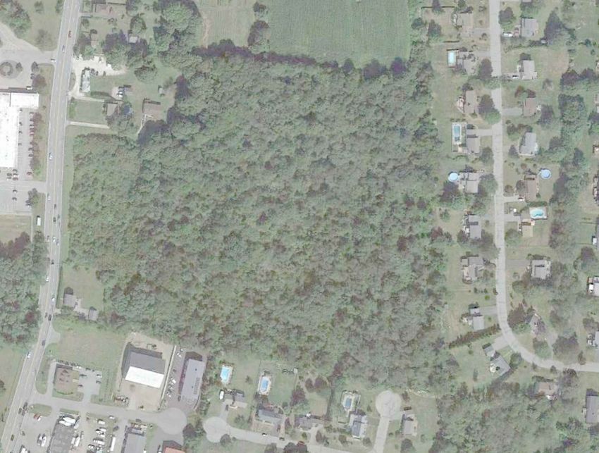
The proposed project site is approximately 18.3 acres in total. The site is currently undeveloped with tree
cover and there are no structures on the site. The parcel area is zoned light industrial on the eastern side of
the parcel and commercial on the western portion along West Main Road. (See attached Zoning Map,
Attachment A).
The proposed solar PV array will be limited to 2,520 KW AC by National Grid as shown on Impact Study
(Attachment B). The current DC rating is 3,160 kW DC consisting of approximately 7,520 PV Modules on a
ground mounted racking system with a typical post drive of 6 feet. Based on final module selection the DC
rating may be increased, the increase in DC rating will not increase the size of the array area. The project
will consist of 42 (each 60 kW) string inverters mounted on the back of the racking. The inverters acoustic
noise rating is < 60 dBA at 1 meter at room temperature.
The solar PV array will be connected from the customer-owned electrical equipment (transformers and
switchboards) located within the fence line to new National Grid owned poles and then to the
interconnection point at an existing National Grid pole (#102) on West Main Road (See Attachment C,
Project Plans, Drawing C-101). Access to the site will be from West Main Road. The access road to the site
will be a minimum of 20 feet wide with a 12-foot gate at the fence line and designed to conform to all town
and RIDOT requirements. There will be minimal line of sight from West Main Road into the array area due
to existing and proposed vegetation.
An area encompassing approximately 12.2 acres will be cleared of trees and other vegetation, as shown on
the attached Project Plans (Attachment C, Drawing C-101). This includes the area of the arrays and trees to
be removed to prevent shading. The proposed solar arrays will be surrounded by a six (6)-foot security
fence. The fence will be elevated six (6) inches above ground. The area within the fence line is approximately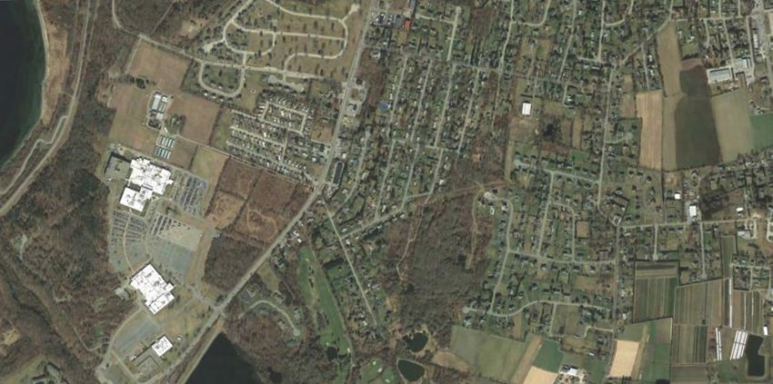
3.16 MW DC Ground Mount Solar PV Development | West Main Road - Map 44, Lot 15

8.2 acres or 45% of the lot. Minimum 50-foot buffers from the fence line to the adjoining property
boundaries will be maintained on all sides of the development. In areas where existing vegetation may not
be sufficient for screening the arrays, additional vegetation is proposed as shown on the attached
landscaping plans (Attachment D).

The solar arrays will be a maximum of 10 feet in height. A typical profile of the arrays is shown on the Project
Plans, Drawing C-502. Areas under and surrounding the arrays will be covered with a slow growing,
pollinator friendly seed mix and maintained regularly to manage health and height of the grass cover.

There are no wetlands on the site and the parcel is outside the 100-year floodplain zone (as shown on FEMA
Map 44005C0084J, dated September 4, 2013, Attachment E). Review of on-line RIDEM and Town records
shows that the site is not in the Watershed Protection Overlay District. No known threatened or endangered
species or protected habitat are present at the site, but since the Northern Long-Eared Bat (NLEB) is
endangered throughout Rhode Island, a Consultation Form will be submitted to U.S. Fish and Wildlife
Service to verify that the project will not impact the NLEB.

The project contours are shown on the existing and proposed project plans (Drawings V-101 and C-101).
The site slopes predominantly from the northeast corner toward the southwest portion of the parcel,
dropping approximately forty (40) feet across the site from elevation 205 to 165. The solar arrays are
planned to be ground-mounted and placed along existing grades. No significant grading is proposed.
Stormwater analysis is currently underway to assess potential impacts of the solar development on site
runoff.

The operation of the solar development will result in minimal traffic impacts, as site visits will be limited to
site inspections and maintenance. The solar arrays will be screened with vegetation, do not generate
measurable noise or air pollution, are designed to be anti-glare, and the generation of solar power supports
Rhode Island’s energy goal to meet 100% of the state’s electricity demand with renewable energy by 2030.

The project construction is proposed to be scheduled as follows:
            • Site mobilization/erosion controls
            • access road/vegetation clearing/screening
            • Solar foundations/solar panels & controls
            • Electrical connections/poles
            • Fencing and final landscaping
            • Final soil stabilization
            • Start-up and on-going site maintenance

Other regulatory permits required prior to approval of construction include:
        • Physical Alteration Permit Application (PAPA) with Rhode Island DOT.
        • Consultation with the Rhode Island Historical Preservation and Heritage Commission (RIHPHC)
            will be performed to determine the likelihood of the presence of potential state or federal
            historic or archaeological (cultural) resources at the Site.
        • Rhode Island Pollutant Discharge Elimination System (RIPDES) Construction General Permit for
            Stormwater Discharges
        • FAA, if required

Additional information on the project’s compliance with the Town’s Zoning requirements is included in
Attachment F and an Abutters List and Map are included in Attachment G.

                                                       2
Attachment A

Zoning Map

                      Town of Portsmouth, Rhode Island                                                                                                 100 m
                                                                                                                                                         500 ft
                      Selected Parcel: 0 WEST MAIN RD ID: 44-15                                                                                                                                                          MainStreetGIS, LLC
                                                                                                                                                                                                                         www.mainstreetgis.com
                      Printed on 12/8/2020

This map is for informational purposes only. It is not for appraisal of, description of, or conveyance of land. The Town of Portsmouth, Rhode Island and MainStreetGIS, LLC assume no legal responsibility for the information contained herein.

                                                                                                                   Sheet 8 of 12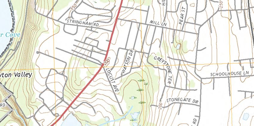
Attachment B
DISTRIBUTION PLANNING                                         Doc. RI-29822030
                                                                                                  Case #00295175
                                         DOCUMENT
                                         Interconnection Study                                      Page 1 of 31
                                   Complex Generating Facility - R.I.P.U.C. 2180               Version 1.0 02/16/2021
                                              Econox Group Inc
                                2,520 kW / kVA, Inverter Based Photovoltaic
                                       Plat 44 Lot 15 West Main Road,
                                                                                                      FINAL
                                            Portsmouth, RI 02871

                             System Impact Study
                for Distributed Generation Interconnection to
                        National Grid’s 13.8 kV System

                      DG WR:                           RI-29822030

                      DG Case#:                        00295175
                      Applicant:                       Econox Group Inc

                      Address:                         Plat 44 Lot 15, West Main Road
                      City:                            Portsmouth
                      DG kW/kVA:                       2,520 kW / kVA

                      DG Type:                         Inverter Based Photovoltaic

                      Feeder:                          Jepson (New 13.8 kV) 37W2

      "THIS DOCUMENT AND ANY ATTACHMENTS HERETO ("DOCUMENT") IS MADE AVAILABLE BY NATIONAL GRID USA UPON
      AND SUBJECT TO THE EXPRESS UNDERSTANDING THAT: (A) NEITHER NATIONAL GRID NOR ANY OF ITS OFFICERS,
      DIRECTORS, AFFILIATES, AGENTS, OR EMPLOYEES MAKES ANY WARRANTY, ASSURANCE, GUARANTY, OR
      REPRESENTATION WITH RESPECT TO THE CONTENTS OF THE DOCUMENT OR THE ACCURACY OR COMPLETENESS OF
      THE INFORMATION CONTAINED OR REFERENCED IN THE DOCUMENT, AND (B) NATIONAL GRID USA, ITS OFFICERS,
      DIRECTORS, AFFILIATES, AGENTS, AND EMPLOYEES SHALL NOT HAVE ANY LIABILITY OR RESPONSIBILITY FOR
      INACCURACIES, ERRORS, OR OMISSIONS IN, OR ANY BUSINESS OR POLICY DECISIONS MADE BY ANY DIRECT OR
      INDIRECT RECIPIENT IN RELIANCE ON, THIS DOCUMENT OR THE INFORMATION CONTAINED OR REFERENCED THEREIN;
      ALL SUCH LIABILITY IS EXPRESSLY DISCLAIMED

PRINTED OR DOWNLOADED COPIES ARE NOT DOCUMENT CONTROLLED.
File: SP. RI-29822030                                          Originating Department:           Sponsor:
App File: 01-RI_29822030_Portsmouth_FINAL_V1.0_02.16.2021      Distribution Planning & Asset     Customer Energy
                                                               Management – NE                   Integration-NE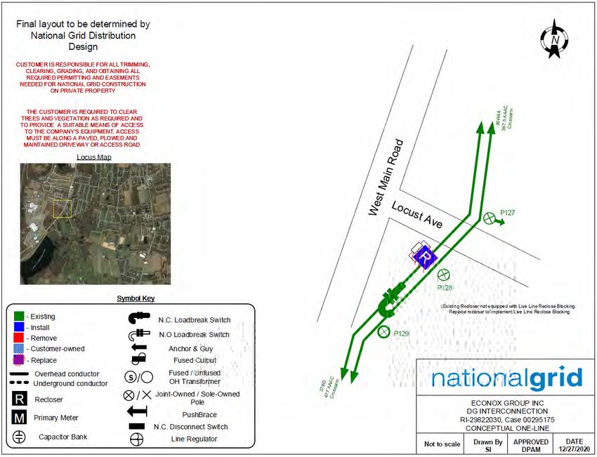
DISTRIBUTION PLANNING                                                                         Doc. RI-29822030
                                                                                                                                                      Case #00295175
                                                             DOCUMENT
                                                                  Interconnection Study                                                                  Page 2 of 31
                                                    Complex Generating Facility - R.I.P.U.C. 2180                                               Version 1.0 02/16/2021
                                                               Econox Group Inc
                                                 2,520 kW / kVA, Inverter Based Photovoltaic
                                                        Plat 44 Lot 15 West Main Road,
                                                                                                                                                             FINAL
                                                             Portsmouth, RI 02871

                                                                                  Table of Contents
Section                                                                                                                                                                           Page
DEFINITIONS ........................................................................................................................................................................ 4
EXECUTIVE SUMMARY ......................................................................................................................................................... 5
1.0     INTRODUCTION .......................................................................................................................................................... 6
2.0     PROJECT DESCRIPTION ............................................................................................................................................... 6
    2.1      CUSTOMER FACILITY ........................................................................................................................................................... 6
    2.2      COMPANY AREA EPS .......................................................................................................................................................... 7
    2.3      INTERCONNECTION ............................................................................................................................................................. 8
3.0     POWER FLOW ANALYSIS ............................................................................................................................................. 9
    3.1      POWER FLOW PRE-EXISTING CONDITIONS............................................................................................................................. 10
    3.2      REVERSE POWER FLOW AT SUBSTATION ............................................................................................................................... 10
    3.3      INTERCONNECTING CIRCUIT LOAD FLOW ANALYSIS ................................................................................................................. 10
    3.4      INTERCONNECTING CIRCUIT VOLTAGE ANALYSIS ..................................................................................................................... 10
    3.5      FLICKER ANALYSIS ............................................................................................................................................................. 11
4.0     RISK OF ISLANDING .................................................................................................................................................. 12
    4.1      ISLANDING ANALYSIS (ESB 756D SECTION 7.6.12)................................................................................................................ 12
5.0     SHORT CIRCUIT AND PROTECTION ANALYSIS COMPANY FACILITIES ......................................................................... 12
    5.1      FAULT DETECTION AT SUBSTATION (ESB 756D SECTION 6.2.2) ............................................................................................... 13
    5.2      PCC IMPEDANCE .............................................................................................................................................................. 14
    5.3      FAULT CURRENT CONTRIBUTIONS ........................................................................................................................................ 14
    5.4      SUBSTATION PROTECTIVE DEVICE MODIFICATIONS.................................................................................................................. 14
    5.5      AREA EPS PROTECTIVE DEVICE COORDINATION ..................................................................................................................... 14
6.0     CUSTOMER EQUIPMENT REQUIREMENTS ................................................................................................................ 15
    6.1 REVENUE METERING REQUIREMENTS (ESB 756D SECTION 7.2.2 AND 7.2.3) ............................................................................ 15
    6.2 INTERCONNECTING TRANSFORMER (ESB 756D SECTION 7.3) .................................................................................................. 16
    6.3 EFFECTIVE GROUNDING (ESB 756D SECTION 7.3.2.1) ........................................................................................................... 16
    6.4 MANUAL GENERATOR DISCONNECTING MEANS (ESB 756D SECTION 7.4) ................................................................................. 16
    6.5 PRIMARY PROTECTION (ESB 756D SECTION 7.6 & 7.8) ......................................................................................................... 16
       6.5.1  Primary Protective Relaying (ESB 756D Section 7.6.1, 7.6.2, 7.6.11, & 7.8) ...................................................... 16
       6.5.2  Primary Frequency Protection (ESB 756D Section 7.6.8, 7.6.11.1, and 7.8) ....................................................... 17
       6.5.3  Primary Voltage Relay Elements (ESB 756D Section 7.6.7, 7.6.11.1, and 7.8) ................................................... 17
    6.6 SECONDARY PROTECTION................................................................................................................................................... 17
       6.6.1  Generator Interrupting Device (ESB 756D Section 7.5) ...................................................................................... 17
    6.7 CUSTOMER CABLING ......................................................................................................................................................... 18
7.0     TELEMETRY AND TELECOMMUNICATIONS ............................................................................................................... 18
8.0     INSPECTION, COMPLIANCE VERIFICATION, CUSTOMER TESTING, AND ENERGIZATION REQUIREMENTS .................. 18
    8.1      INSPECTIONS AND COMPLIANCE VERIFICATION ....................................................................................................................... 18
   PRINTED OR DOWNLOADED COPIES ARE NOT DOCUMENT CONTROLLED.
   File: SP. RI-29822030                                                                           Originating Department:                          Sponsor:
   App File: 01-RI_29822030_Portsmouth_FINAL_V1.0_02.16.2021                                       Distribution Planning & Asset                    Customer Energy
                                                                                                   Management – NE                                  Integration-NE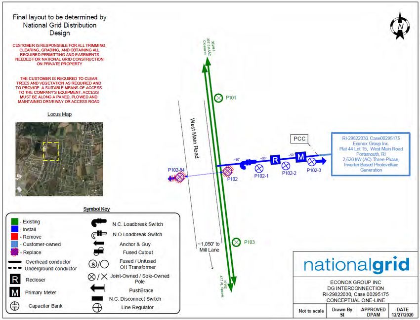
DISTRIBUTION PLANNING                                                                            Doc. RI-29822030
                                                                                                                                                        Case #00295175
                                                            DOCUMENT
                                                                  Interconnection Study                                                                    Page 3 of 31
                                                   Complex Generating Facility - R.I.P.U.C. 2180                                                  Version 1.0 02/16/2021
                                                              Econox Group Inc
                                                2,520 kW / kVA, Inverter Based Photovoltaic
                                                       Plat 44 Lot 15 West Main Road,
                                                                                                                                                                FINAL
                                                            Portsmouth, RI 02871

    8.2      TESTING AND COMMISSIONING ........................................................................................................................................... 19
    8.3      ENERGIZATION AND SYNCHRONIZATION ................................................................................................................................ 19
9.0     COST ESTIMATE ........................................................................................................................................................ 21
10.0         CONCLUSION ....................................................................................................................................................... 23
11.0         REVISION HISTORY ............................................................................................................................................... 23
Appendix A              Revenue Metering Phone Line Requirements .................................................................................................................. 24
Appendix B              System Modification Diagrams ......................................................................................................................................... 26
Appendix C              Customer Site and Single Line Diagram ............................................................................................................................ 29

                                                                                        List of Tables
    Table                                                                                                                                                                            Page
TABLE 1: GENERATION AT THE SUBSTATION AND INTERCONNECTING CIRCUIT ........................................................................ 8
TABLE 2: RECLOSER LOCATIONS .................................................................................................................................................. 8
TABLE 3: CAPACITOR LOCATIONS ................................................................................................................................................ 8
TABLE 4: REGULATOR LOCATIONS ............................................................................................................................................... 8
TABLE 5: GENERATION CONSIDERED FOR RISK OF ISLANDING ANALYSIS ................................................................................ 12
TABLE 6: RECLOSER LOCATIONS ................................................................................................................................................ 12
TABLE 7: FAULT DUTY ................................................................................................................................................................ 14
TABLE 8: COST ESTIMATES ......................................................................................................................................................... 21

   PRINTED OR DOWNLOADED COPIES ARE NOT DOCUMENT CONTROLLED.
   File: SP. RI-29822030                                                                            Originating Department:                           Sponsor:
   App File: 01-RI_29822030_Portsmouth_FINAL_V1.0_02.16.2021                                        Distribution Planning & Asset                     Customer Energy
                                                                                                    Management – NE                                   Integration-NE
DISTRIBUTION PLANNING                                       Doc. RI-29822030
                                                                                                 Case #00295175
                                          DOCUMENT
                                           Interconnection Study                                   Page 4 of 31
                                   Complex Generating Facility - R.I.P.U.C. 2180              Version 1.0 02/16/2021
                                              Econox Group Inc
                                2,520 kW / kVA, Inverter Based Photovoltaic
                                       Plat 44 Lot 15 West Main Road,
                                                                                                     FINAL
                                            Portsmouth, RI 02871

Definitions

The following is a list of acronyms/synonyms used in this Interconnection Study:
BESS – Battery Energy Storage System
Company – National Grid
Customer – The interconnecting customer of this project
DG – Distributed Generation
DER – Distributed Energy Resources
DTT – Direct Transfer Trip
EPS – Electrical Power System
ESB – National Grid’s Electrical Service Bulletin
Facility – The distributed generating facility for this project, including all related appurtenances and
           equipment.
IA – Interconnection Application
Interconnecting Circuit – Circuit to which the Facility will connect
ISA – Interconnection Service Agreement
ISO-NE – Independent System Operator of New England
NPCC – Northeast Power Coordinating Council
PCC – Point of Common Coupling (point of demarcation between the Customer and Company facilities)
PF – Power Factor
Plt – Long term flicker emission limit
Project – The interconnection of the Facility to the Company electrical power system
Pst – Short Term flicker emission limit
P.U. – Per Unit
PV – Photovoltaic

  PRINTED OR DOWNLOADED COPIES ARE NOT DOCUMENT CONTROLLED.
  File: SP. RI-29822030                                       Originating Department:           Sponsor:
  App File: 01-RI_29822030_Portsmouth_FINAL_V1.0_02.16.2021   Distribution Planning & Asset     Customer Energy
                                                              Management – NE                   Integration-NE
DISTRIBUTION PLANNING                                       Doc. RI-29822030
                                                                                                Case #00295175
                                         DOCUMENT
                                          Interconnection Study                                   Page 5 of 31
                                  Complex Generating Facility - R.I.P.U.C. 2180              Version 1.0 02/16/2021
                                             Econox Group Inc
                               2,520 kW / kVA, Inverter Based Photovoltaic
                                      Plat 44 Lot 15 West Main Road,
                                                                                                    FINAL
                                           Portsmouth, RI 02871

Executive Summary

The Company has completed the Impact Study, for the interconnection of Econox Group Inc,
(“Customer”) a 2,520 kW / kVA, (“the Facility”), to its 13.8 kV distribution system, (“the Project”), and
presents the conclusions of the study herein.
The interconnection requirements specified are exclusive to this project and are based upon the most
recent information submitted by the Customer, which is attached for reference in Appendix C. Any further
design changes made by the Customer post IA without the Company’s knowledge, review, and/or
approval will render the findings of this report null and void.

System Modifications
In general, the Project was found to be feasible with certain modifications to the existing Company System
and operating conditions, which are described in detail in the body of this Study. Significant modifications
include:
   1. Replace existing recloser at Pole #128 West Main Road, Portsmouth and implement live line
      reclose blocking. New settings have also been proposed for this recloser. (Section 5.6)
   2. Installation of pole mounted equipment including gang operated air break switch, recloser, and
      metering, four (4) poles and installation of approximately 150' of three phase, 1/0 AL crossarm
      primary overhead conductor for the POI to PCC set up. (Appendix B-1, Section 2.3)

Special Operating Requirements
The Customer is required to comply with the following special operating requirements in order to
interconnect to the Company EPS:
   1. The reactive contribution of the Facility at the PCC operates at unity power factor. (Section 3.5)

Cost Estimate
Refer to the Cost Estimate table in Section 9.0 for a listing of major modifications and associated costs.
The total estimated planning grade cost of the work associated with the interconnection of the Facility, is
$212,439 +/-25% and includes Company EPS modifications, Customer interconnection, and taxes. An
estimated construction schedule will be provided in the final Interconnection Service Agreement.

 PRINTED OR DOWNLOADED COPIES ARE NOT DOCUMENT CONTROLLED.
 File: SP. RI-29822030                                       Originating Department:           Sponsor:
 App File: 01-RI_29822030_Portsmouth_FINAL_V1.0_02.16.2021   Distribution Planning & Asset     Customer Energy
                                                             Management – NE                   Integration-NE
DISTRIBUTION PLANNING Doc. RI-29822030
Case #00295175
DOCUMENT
Interconnection Study Page 6 of 31
Complex Generating Facility - R.I.P.U.C. 2180 Version 1.0 02/16/2021
Econox Group Inc
2,520 kW / kVA, Inverter Based Photovoltaic
Plat 44 Lot 15 West Main Road,
FINAL
Portsmouth, RI 02871
1.0 Introduction
The Customer has requested interconnection of a Facility to the Company’s existing
infrastructure.
The analysis utilized Customer provided documentation to examine the effects on the Company
system when the new Facility is connected. The results identify required modifications to the
Customer one line diagram(s) and Company infrastructure, in order to accommodate the
interconnection. As such, the interconnection of the Facility has been evaluated under specific
conditions. Should the Customer make any changes to the design, other than those identified in
this study, it may require additional time for review, and possibly additional cost.
In accordance with the R.I.P.U.C. 2180 tariff and the Company’s ESB series, the Company has
completed an Impact Study to determine the scope of the required modifications to its EPS and/or
the Facility for providing the requested interconnection service.
Analysis will be performed in accordance with applicable reliability standards and study practices,
and in compliance with the applicable codes, standards, and guidelines listed in the Company’s
Electric System Bulletin No. 756 Appendix D: Distributed Generation Connected to National Grid
Distribution Facilities Per The Rhode Island Standards for Interconnecting Distributed Generation
(“ESB756D”) to determine the incremental impact and any potential adverse impacts associated
with the interconnection of the Facility to the EPS.
2.0 Project Description
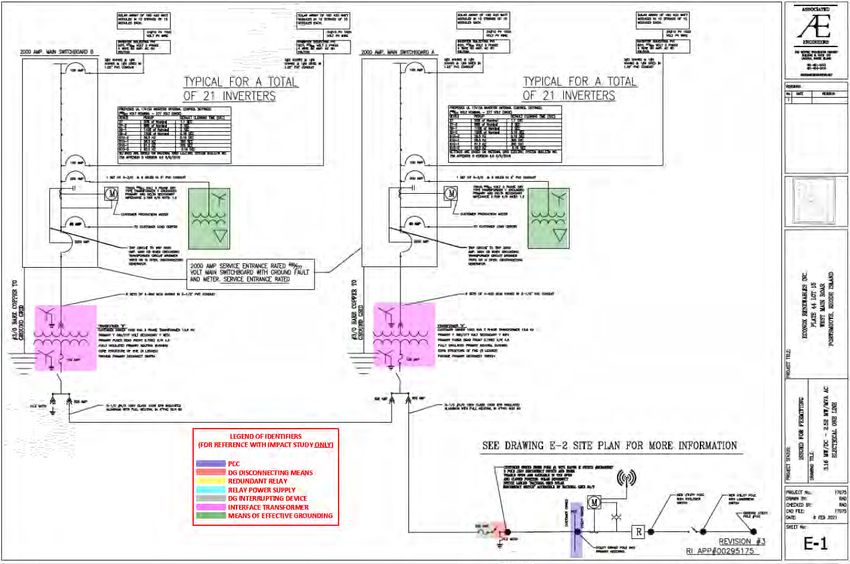
2.1 Customer Facility
The Customer proposes to install the following:
• Forty-two (42) Customer owned 60 kW / kVA, three phase, 480V Solectria PVI
60TL inverters for a total of 2,520 kW / kVA inverter based DG.
• Two (2) Customer owned 1,500 kVA, 13.8 kV wye grounded primary to 480V
wye grounded secondary interface transformers, each with an impedance of
Z=5.75% and X/R=4.5.
• Two (2) Customer owned 75 kVA, 480 V wye grounded primary to delta
secondary grounding transformers, each with an impedance of Z=2.75% and
X/R =1.2
• One (1) set of Customer owned 200 A fuses.
PRINTED OR DOWNLOADED COPIES ARE NOT DOCUMENT CONTROLLED.
File: SP. RI-29822030 Originating Department: Sponsor:
App File: 01-RI_29822030_Portsmouth_FINAL_V1.0_02.16.2021 Distribution Planning & Asset Customer Energy
Management – NE Integration-NEDISTRIBUTION PLANNING Doc. RI-29822030
Case #00295175
DOCUMENT
Interconnection Study Page 7 of 31
Complex Generating Facility - R.I.P.U.C. 2180 Version 1.0 02/16/2021
Econox Group Inc
2,520 kW / kVA, Inverter Based Photovoltaic
Plat 44 Lot 15 West Main Road,
FINAL
Portsmouth, RI 02871
• One (1) Customer owned Eaton M Switch #MIRA2SR2T, 15 kV disconnect
switch accessible by National Grid 24/7.
A copy of the Customer one lines are provided in Appendix C, illustrating the
Customer’s proposed design and proposed interconnection to the area EPS. The
Customer documents are not binding and shall require modifications and/or
clarification as identified herein.
The following parameters were assessed as part of the Project evaluation:
1. The voltage and frequency trip settings as shown on the one line (dated
02/08/2021).
Any advanced inverter functionality other than that specifically called out on the
Customer documentation and/or outlined herein shall be subject to additional study
before being enabled.
2.2 Company Area EPS
The area EPS was evaluated, and it was determined that the most viable
interconnecting circuit is the 37W2, a 13.8 kV regulated, three-phase, 4 wire, wye,
effectively-grounded, radial distribution circuit that originates out of the Company’s
Jepson (New 13.8 kV) Substation, in Middletown, RI (the “Interconnecting Circuit”).
The feeder is regulated by way of a load tap changer at the substation. This circuit is
located immediately adjacent to the Facility.
The ability to generate is contingent on this Facility being served by the Interconnecting
Circuit during normal operating conditions. Therefore, if the Interconnecting Circuit is
out of service, or if abnormal operating conditions of the area EPS are in effect, the
Company reserves the right to direct the Customer to disengage the Facility.
The Interconnecting Circuit has the following characteristics:
• Refer to Section 3.0 for circuit loading characteristics.
• The existing and in-process generation at the substation and on the
interconnecting circuit is summarized in Table 1. Values shown are based on
full nameplate DG output:
PRINTED OR DOWNLOADED COPIES ARE NOT DOCUMENT CONTROLLED.
File: SP. RI-29822030 Originating Department: Sponsor:
App File: 01-RI_29822030_Portsmouth_FINAL_V1.0_02.16.2021 Distribution Planning & Asset Customer Energy
Management – NE Integration-NEDISTRIBUTION PLANNING Doc. RI-29822030
Case #00295175
DOCUMENT
Interconnection Study Page 8 of 31
Complex Generating Facility - R.I.P.U.C. 2180 Version 1.0 02/16/2021
Econox Group Inc
2,520 kW / kVA, Inverter Based Photovoltaic
Plat 44 Lot 15 West Main Road,
FINAL
Portsmouth, RI 02871
Generation installed and Generation in process Generation proposed
TOTAL
Feeder operating at time of study at time of study for this Project
(kW)
(kW) (kW) (kW)
37W1 272 1,311 0 1,583
37W2 77 0 2,520 2,597
37W3 798 44 0 842
37W4 483 0 0 483
37W5 1,273 0 0 1,273
37W6 2,108 1,119 0 3,227
TOTAL 5,011 2,474 2,520 10,005
Table 1: Generation at the Substation and Interconnecting Circuit
• There is one (1) existing recloser on the circuit, which is located in between the
substation and the facility, summarized in Table 2. Refer to Section 5 for further
discussion on any required modifications.
In between
Mid-line recloser, or existing
Location Status Facility and
DG project PCC recloser
Substation
Pole #128, West Main Road
In Service Mid-line Yes
Portsmouth
Table 2: Recloser Locations
• There is a total of 1,800 kVAR in existing capacitor banks installed on this
circuit, summarized in Table 3. Refer to Section 3 for further discussion on any
required modifications.
Size
Location Type Control Status
(kVAR)
Pole #2, Raytheon ROW, Portsmouth 600 Switched Voltage In Service
Pole #2X, Raytheon ROW, Portsmouth 600 Fixed NA In Service
Pole #4, Raytheon ROW, Portsmouth 600 Fixed NA In Service
Table 3: Capacitor Locations
• The only regulation on this circuit is through the supply transformer’s LTC
control at the substation, summarized in Table 4.
Location Status
T6 LTC Jepson Substation In Service
Table 4: Regulator Locations
2.3 Interconnection
Refer to the interconnection diagram in Appendix B for approximate PCC location.
PRINTED OR DOWNLOADED COPIES ARE NOT DOCUMENT CONTROLLED.
File: SP. RI-29822030 Originating Department: Sponsor:
App File: 01-RI_29822030_Portsmouth_FINAL_V1.0_02.16.2021 Distribution Planning & Asset Customer Energy
Management – NE Integration-NEDISTRIBUTION PLANNING Doc. RI-29822030
Case #00295175
DOCUMENT
Interconnection Study Page 9 of 31
Complex Generating Facility - R.I.P.U.C. 2180 Version 1.0 02/16/2021
Econox Group Inc
2,520 kW / kVA, Inverter Based Photovoltaic
Plat 44 Lot 15 West Main Road,
FINAL
Portsmouth, RI 02871
Should the Customer elect to move forward with the Project, the Company’s Design
Personnel will specify the exact location of the Company’s facilities and installation
details. The Customer shall be responsible for obtaining all easements and permits
required for any line extension not on public way in accordance with the Company’s
requirements.
The Customer shall provide unencumbered direct access to the Company’s facilities
along an accessible plowed driveway or road, where the equipment is not behind the
Customer's locked gate. In those cases where Company equipment is required to be
behind the Customer's locked gate, double locking, with both the Company’s and
Customer’s locks shall be employed.
For this Project, the PCC is defined as the point where the Customer owned
conductors terminate to the Company revenue meter, which is located at Pole #102-
3, West Main Road, Portsmouth, RI. The Customer must install their facilities up to the
Company revenue meter. The Customer must provide sufficient conductor to allow the
Company to make final connections at the meter pole. The Company will provide final
connection of the Customer conductors to the Company meter.
If National Grid right of way (R.O.W) is involved, then the Customer shall provide
detailed drawings of any planned construction within any National Grid R.O.W., for the
Company’s review and subsequent approval, showing elevation grades of all phases
of construction within the R. O. W. before any construction may begin. Plans and
drawings must be submitted that meet all the Company’s requirements before the
interconnection process can move forward. These plans shall be submitted to National
Grid’s R.O.W./Real-Estate group and the Transmission R.O.W. Engineering and
construction group for review and comment before any construction can be allowed to
move forward. There may be additional costs and subsequent delays involved with the
review, and, or oversight of any construction in, or adjacent to, the Company’s R.O.W.,
and if any Company owned facilities need modification as a result of the Customer’s
proposed construction. These costs will be in addition to, and outside of the scope of,
this SIS. Failure of the Customer to reimburse the Company for these costs may delay
or negate the interconnection process.
3.0 Power Flow Analysis
The power flow analysis was substantially performed using electrical system modeling software.
A model of the Interconnecting Circuit, as described in Section 2.2, was developed based on data
extracted from the Company’s Geographical Information System (“GIS”). A field review of the
feeder was performed on 11/20/2020.
The analysis considered cases at peak load (2,095 kVA @ 95.61% Leading PF) and net minimum
load (1,155 kVA @ 76.1% Lagging PF) at time of maximum expected generation (9:00AM –
6:00PM) on the circuit.
PRINTED OR DOWNLOADED COPIES ARE NOT DOCUMENT CONTROLLED.
File: SP. RI-29822030 Originating Department: Sponsor:
App File: 01-RI_29822030_Portsmouth_FINAL_V1.0_02.16.2021 Distribution Planning & Asset Customer Energy
Management – NE Integration-NEDISTRIBUTION PLANNING Doc. RI-29822030
Case #00295175
DOCUMENT
Interconnection Study Page 10 of 31
Complex Generating Facility - R.I.P.U.C. 2180 Version 1.0 02/16/2021
Econox Group Inc
2,520 kW / kVA, Inverter Based Photovoltaic
Plat 44 Lot 15 West Main Road,
FINAL
Portsmouth, RI 02871
Circuit peak and minimum load values have been taken from the Company’s historical load data
that has been compiled over the past 12 months.
3.1 Power Flow Pre-Existing Conditions
The Substation loading shows that the circuit power factor during min and max loading
appears to be leading. This pre-existing issue has been discussed with the Company’s
Long-Term Planner/Field Engineer for this area. To remedy this issue, the following
modifications are required:
• Implement VAR control on the existing 600 kVAR switched capacitor on Pole
#2 Raytheon ROW, Portsmouth.
This pre-existing condition is not expected to have an effect on the cost or schedule
for this Project.
3.2 Reverse Power Flow at Substation
The possibility of the Facility causing reverse power flow through the Company’s
substation transformer was reviewed.
Analysis shows that the maximum potential generation exceeds the observed
minimum load. However, the substation is currently equipped with bi-directional
metering which were previously installed for reasons unrelated to DG work. Therefore,
no additional work is required at the substation, and this Customer is not responsible
for costs related to the existing substation equipment.
3.3 Interconnecting Circuit Load Flow Analysis
The area EPS was examined with and without the Facility operating at full output. The
analysis demonstrated that the addition of the Facility will not create thermal loading
problems on the Interconnecting Circuit, or the associated substation.
Specifically, no conductor, transformer, or voltage regulator overloads occur as a
result of this interconnection. All Company owned mainline conductor and distribution
facilities are thermally large enough to accommodate the proposed generation.
3.4 Interconnecting Circuit Voltage Analysis
The Company is obligated to hold distribution voltages at customer service points to
defined limits in ANSI Standard C84.1- 2006. Range A of the ANSI standard requires
the Company to hold voltage within +/- 5% of nominal at the PCC.
Under emergency conditions, voltage on the system could reach 90% of nominal prior
to corrective action being taken. The Customer is advised to consider this in planning
PRINTED OR DOWNLOADED COPIES ARE NOT DOCUMENT CONTROLLED.
File: SP. RI-29822030 Originating Department: Sponsor:
App File: 01-RI_29822030_Portsmouth_FINAL_V1.0_02.16.2021 Distribution Planning & Asset Customer Energy
Management – NE Integration-NEDISTRIBUTION PLANNING Doc. RI-29822030
Case #00295175
DOCUMENT
Interconnection Study Page 11 of 31
Complex Generating Facility - R.I.P.U.C. 2180 Version 1.0 02/16/2021
Econox Group Inc
2,520 kW / kVA, Inverter Based Photovoltaic
Plat 44 Lot 15 West Main Road,
FINAL
Portsmouth, RI 02871
their system requirements and equipment settings, however, no warranties or
guarantees are implied.
Under normal operating conditions it is expected that the Company will be able to meet
its obligations for ANSI C84.1 with the system generation at full power. The Customer
must maintain voltage at the PCC at +/- 5% of nominal under normal conditions. Also,
the PV interconnection shall not contribute to greater than a 3.0% change in steady
state voltage on the EPS under any conditions.
The analysis of this facility determined that when the Facility generation is at full output,
the voltage range at the PCC was within acceptable limits.
3.5 Flicker Analysis
The IEEE 1547 standard and IEEE 1453 flicker assessments were used to estimate
whether or not this site would be likely to cause unacceptable voltage flicker on the
interconnecting feeder. This method evaluates for both short term and long term
voltage flicker against IEEE1547-2018 Table 25 - DER Flicker Emission Limits.
Analysis shows that Pst and Plt are within acceptable limits and no mitigation for voltage
flicker is recommended.
The IEEE Recommended Practice for Measurement and Limits of Voltage
Fluctuations and Associated Light Flicker on AC Power Systems, IEEE Std. 1453-
2015 was used as a basis for flicker and voltage fluctuation analysis.
This Facility was modeled using the Long Term Dynamics module of CYME1. A long
term dynamic profile for the Facility was used that simulates the voltage fluctuation of
the site over a 6 hour period. Other significant DG existing or in process ahead of this
Project were modeled at full output and modeled with the appropriate voltage
fluctuation curve to simulate reasonable voltage fluctuations.
The generation profile used is based on live metered data from a PV site that is similar
in size to this Project. The data is intended to simulate realistic power output from the
site, resulting in a varied output from the PV.
Given the nature of flicker, it is impossible to predict voltage flicker under all
conceivable environmental conditions. Therefore, the flicker results are used as a
metric to evaluate whether or not there is a readily apparent concern related to voltage
flicker.
The Company will not be held liable for any power quality issues that may develop with
the Customer or any other customers as result of the interconnection of this
generation.
1 CYME Power Engineering Software, Version 8.1, Revision 01, Build 115, Copyright © 1986-2017, Cooper Industries, Ltd.
PRINTED OR DOWNLOADED COPIES ARE NOT DOCUMENT CONTROLLED.
File: SP. RI-29822030 Originating Department: Sponsor:
App File: 01-RI_29822030_Portsmouth_FINAL_V1.0_02.16.2021 Distribution Planning & Asset Customer Energy
Management – NE Integration-NEDISTRIBUTION PLANNING Doc. RI-29822030
Case #00295175
DOCUMENT
Interconnection Study Page 12 of 31
Complex Generating Facility - R.I.P.U.C. 2180 Version 1.0 02/16/2021
Econox Group Inc
2,520 kW / kVA, Inverter Based Photovoltaic
Plat 44 Lot 15 West Main Road,
FINAL
Portsmouth, RI 02871
Analysis shows that the predicted flicker and voltage fluctuations are expected to be
acceptable, provided that the following conditions are met:
• The system modifications identified elsewhere in this study are implemented.
• The reactive contribution of the PV at the PCC operates at unity power factor.
4.0 Risk of Islanding
4.1 Islanding Analysis (ESB 756D Section 7.6.12)
The project was screened for the potential of islanding risk. Per IEEE 1547 section
4.4.1 Unintentional Islanding, for an unintentional island in which the DG energizes a
portion of the Area EPS through the PCC, the DG interconnection system shall detect
the island and cease to energize the Area EPS within two seconds of the formation of
an island.
Based on known in-service and in-progress projects at the time of study, the
generation shown in Table 5 was considered on this feeder. Three-phase projects
greater than 25kW are listed individually. All other projects below 25kW are listed as
a single line item.
Project Size
Certified / Non-Certified
(kW)
77 All ProjectsDISTRIBUTION PLANNING Doc. RI-29822030
Case #00295175
DOCUMENT
Interconnection Study Page 13 of 31
Complex Generating Facility - R.I.P.U.C. 2180 Version 1.0 02/16/2021
Econox Group Inc
2,520 kW / kVA, Inverter Based Photovoltaic
Plat 44 Lot 15 West Main Road,
FINAL
Portsmouth, RI 02871
interconnection tariff and the requirements of the Company’s ESB 756D. The Interconnecting
Circuit, including all relevant DG was modeled in a software package called ASPEN OneLiner2.
The model was developed using Company records for feeder characteristics, and Customer
provided documentation. Refer to Section 2.1.1 for any assumptions made in the model.
5.1 Fault Detection at Substation (ESB 756D Section 6.2.2)
Addition of generation sources to distribution feeders can result in the backfeeding of
the substation transformers, effectively turning a station designed for load into a
generation step-up transformer. The Company’s typical 15kV class substation
transformer has a delta connection on the transmission side and wye-grounded
connection on the distribution side. Due to the transformer's configuration, it cannot
contribute zero sequence ground fault current to single line to ground faults on a
transmission line, and the voltage on the unfaulted phases rises significantly and
rapidly. These overvoltages have potential to exceed insulation levels of the station
and transmission line equipment, and maximum continuous operating voltage of surge
arresters. Zero sequence voltage protection (commonly referred to as “3V0”) on the
primary side of the transformer is required in order to detect these overvoltage
conditions. This 3V0 protection will disconnect the generation from the substation
transformer and stop the generation and transformer from contributing to the
transmission-side overvoltage condition.
Detailed analysis was completed to determine whether the interconnection of the
Facility, in conjunction with existing connected facilities, may pose significant risk of
causing temporary over-voltage conditions to develop on the system during line to
ground faults on the high side of the substation transformer. The load to generation
match at the substation has been evaluated assuming minimum load, maximum
generation, and one feeder out of service in order to determine if substation
modifications are required.
For this Project, results indicate that the Facility poses a significant risk of causing
temporary overvoltage to develop on the primary side of the substation transformer.
Consequently, 3V0 will be required at the substation’s 5TR, 115kV delta – 13.8kV Grd-
Y, supply transformer and also 6TR, 115kV delta – 13.8kV Grd-Y, supply transformer
However, the substation is currently equipped with 3V0 protection which was
previously installed for reasons unrelated to DG work. Therefore, no additional work is
required at the substation, and this Customer is not responsible for costs related to the
existing substation equipment.
2
ASPEN OneLiner V12.5, Build: 19177 (2015.01.28), Copyright © 1987-2013 ASPEN.
PRINTED OR DOWNLOADED COPIES ARE NOT DOCUMENT CONTROLLED.
File: SP. RI-29822030 Originating Department: Sponsor:
App File: 01-RI_29822030_Portsmouth_FINAL_V1.0_02.16.2021 Distribution Planning & Asset Customer Energy
Management – NE Integration-NEDISTRIBUTION PLANNING Doc. RI-29822030
Case #00295175
DOCUMENT
Interconnection Study Page 14 of 31
Complex Generating Facility - R.I.P.U.C. 2180 Version 1.0 02/16/2021
Econox Group Inc
2,520 kW / kVA, Inverter Based Photovoltaic
Plat 44 Lot 15 West Main Road,
FINAL
Portsmouth, RI 02871
5.2 PCC Impedance
The Interconnecting Circuit impedance is shown below in per unit at the PCC for the
proposed Facility, using a 100 MVA base. The PCC location is shown in Appendix B.
These values consider existing system conditions, but not the impact of the
Customer’s new Facility.
Pre-Project
System Impedance at PCC
Z1 = 0.40 + j1.58 p.u.
Z0 = 1.26 + j3.76 p.u.
5.3 Fault Current Contributions
Table 7 summarizes the Facility’s effect on fault current levels at the PCC. Mitigation
strategies are required to accommodate the proposed Facility, as described in
Sections 5.4 and 5.5.
The Customer is responsible for ensuring that their own equipment is rated to
withstand the available fault current according to the NEC and National Grid ESB 750,
which specifies that the fault current should be no more than 80% of the device
interrupting rating.
SUB BUS PCC
PRE PROJECT
(Amps @ 13.8 kV) (Amps @ 13.8 kV)
3-phase (LLL) 7,292 2,560
Phase-Ground (LG) 7,614 1,735
SUB BUS PCC DELTA Ifault DELTA Ifault
POST PROJECT
(Amps @ 13.8 kV) (Amps @ 13.8 kV) @ SUB BUS @PCC
3-phase (LLL) 7,416 2,686 1.70% 4.92%
Phase-Ground (LG) 7,785 1,993 2.25% 14.87%
Table 7: Fault Duty
5.4 Substation Protective Device Modifications
The existing device settings and associated time-current curves were evaluated for
protective devices at the substation. The analysis shows that modifications will not be
required at the substation.
5.5 Area EPS Protective Device Coordination
The Project will require a Company owned recloser at the PCC.
PRINTED OR DOWNLOADED COPIES ARE NOT DOCUMENT CONTROLLED.
File: SP. RI-29822030 Originating Department: Sponsor:
App File: 01-RI_29822030_Portsmouth_FINAL_V1.0_02.16.2021 Distribution Planning & Asset Customer Energy
Management – NE Integration-NEDISTRIBUTION PLANNING Doc. RI-29822030
Case #00295175
DOCUMENT
Interconnection Study Page 15 of 31
Complex Generating Facility - R.I.P.U.C. 2180 Version 1.0 02/16/2021
Econox Group Inc
2,520 kW / kVA, Inverter Based Photovoltaic
Plat 44 Lot 15 West Main Road,
FINAL
Portsmouth, RI 02871
The existing device settings and associated time-current curves were evaluated for
protective devices on the Interconnecting Circuit.
The protection coordination review of the area EPS revealed that the following
modifications to the existing protective devices will be required. Associated costs are
identified in Section 9.0 of this Impact Study. Refer to Appendix B for system
modification drawings:
• Replace existing recloser at Pole #128 West Main Road, Portsmouth and
implement live line reclose blocking. New settings have also been proposed
for this recloser.
6.0 Customer Equipment Requirements
The following Section discusses requirements for Customer owned equipment, which are further
outlined in detail in ESB 756D. References to ESB 756D are provided in each sub-section below.
It is the Customer’s responsibility to comply with all requirements of ESB 756D. Please note that
applicable sections of ESB 756D are referenced for information purposes and may not comprise
the entirety of applicable sections.
In general, the Customer Facility shall have the capability to withstand voltage and current surges
in accordance with the environments defined in IEEE Standard C62.41.2-2002 or IEEE Standard
C37.90.1-2002 as applicable.
6.1 Revenue Metering Requirements (ESB 756D Section 7.2.2 and 7.2.3)
For systems greater than 25kW, Interconnecting Customer shall provide a means of
communication to the National Grid revenue meter. This may be accomplished with
an analog/POTS (Plain Old Telephone Service) phone line (capable of direct inward
dial without human intervention or interference from other devices such as fax
machines, etc.), or, in locations with suitable wireless service, a wireless meter.
Feasibility of wireless service must be demonstrated by Interconnecting Customer, to
the satisfaction of National Grid. If approved, a wireless-enabled meter will be installed,
at the customer's expense. If and when National Grid's retail tariff provides a
mechanism for monthly billing for this service, the customer agrees to the addition of
this charge to their monthly electric bill. Interconnecting Customer shall have the option
to have this charge removed, if and when a POTS phone line to National Grid’s
revenue meter is provided.
Refer to Appendix A Figures A-1 and A-2 - Revenue Meter Phone Line Installation
Guide).
The Customer is advised to contact Generation and Load Administration
(NewGenCoord@iso-ne.com) at ISO New England regarding all metering,
PRINTED OR DOWNLOADED COPIES ARE NOT DOCUMENT CONTROLLED.
File: SP. RI-29822030 Originating Department: Sponsor:
App File: 01-RI_29822030_Portsmouth_FINAL_V1.0_02.16.2021 Distribution Planning & Asset Customer Energy
Management – NE Integration-NEDISTRIBUTION PLANNING Doc. RI-29822030
Case #00295175
DOCUMENT
Interconnection Study Page 16 of 31
Complex Generating Facility - R.I.P.U.C. 2180 Version 1.0 02/16/2021
Econox Group Inc
2,520 kW / kVA, Inverter Based Photovoltaic
Plat 44 Lot 15 West Main Road,
FINAL
Portsmouth, RI 02871
communications circuits, remote access gateway (rig), financial assurance,
paperwork, database updates, etc. that may be required for this Facility.
6.2 Interconnecting Transformer (ESB 756D Section 7.3)
The documentation provided states two (2) interconnecting transformers each 1,500
kVA, 13.8 kV wye-grounded primary and 480 V wye-grounded secondary, with 5.75%
impedance at X/R=4.5. The proposed transformers satisfy the requirements of the
ESB.
6.3 Effective Grounding (ESB 756D Section 7.3.2.1)
The Company requires DG installations to be effectively grounded, which is defined in
IEEE C62.92.1 section 7.1. Additionally, the Company requires that DG installations
do not raise the overvoltage above 125% on the unfaulted phases during ground faults
on the distribution circuits. Refer to IEEE C62.92.1 sections 6.3 and 7.1 for further
details.
The Customer one line shows an interlock such that the Facility cannot be connected
to the EPS when the grounding transformer is offline.
The Customer proposed two (2) 75 kVA, 480 V wye grounded primary to delta
secondary PV grounding transformers, each with an impedance of Z=2.75% and X/R
=1.2, satisfy the effective grounding requirements for the system.
6.4 Manual Generator Disconnecting Means (ESB 756D Section 7.4)
The Customer provided documents satisfy the requirement of this Section of ESB
756D.
6.5 Primary Protection (ESB 756D Section 7.6 & 7.8)
The following section relates to the primary means of protection by the Customer. This
includes the inverter relay functionality.
6.5.1 Primary Protective Relaying (ESB 756D Section 7.6.1, 7.6.2, 7.6.11,
& 7.8)
The Customer provided documents indicate that the inverter will be
provided with an internal relay that will trip the generator interrupting
device. Proposed settings for the 27, 59, 81O/U functions have been
provided for review.
PRINTED OR DOWNLOADED COPIES ARE NOT DOCUMENT CONTROLLED.
File: SP. RI-29822030 Originating Department: Sponsor:
App File: 01-RI_29822030_Portsmouth_FINAL_V1.0_02.16.2021 Distribution Planning & Asset Customer Energy
Management – NE Integration-NEDISTRIBUTION PLANNING Doc. RI-29822030
Case #00295175
DOCUMENT
Interconnection Study Page 17 of 31
Complex Generating Facility - R.I.P.U.C. 2180 Version 1.0 02/16/2021
Econox Group Inc
2,520 kW / kVA, Inverter Based Photovoltaic
Plat 44 Lot 15 West Main Road,
FINAL
Portsmouth, RI 02871
6.5.2 Primary Frequency Protection (ESB 756D Section 7.6.8, 7.6.11.1,
and 7.8)
Frequency elements trip settings for primary relaying are required to
comply with ISO-NE ride-through requirements as described in ESB756D
Section 7.6.8, 7.6.11, and 7.8.
The R.I.P.U.C No. 2180, requires that, the DER cease to energize the area
EPS within 2 seconds, refer to IEEE1547 and UL1741.
The Customer provided documentation, show frequency relay elements in
accordance with ESB 756D.
6.5.3 Primary Voltage Relay Elements (ESB 756D Section 7.6.7, 7.6.11.1,
and 7.8)
The Customer provided documents show undervoltage (27) and
overvoltage (59) elements that satisfy the requirements of this Section of
ESB 756D.
Voltage relay elements trip settings are required to comply with ISO-NE
ride-through requirements as described in ESB756D Section 7.6.11 and
7.8. This requirement is met.
6.6 Secondary Protection
The following section relates to the secondary means of protection, also referred to
as redundant relaying.
6.6.1 Generator Interrupting Device (ESB 756D Section 7.5)
A Company owned recloser is required at the PCC, which will contain utility
facing protective elements (27, 59, 81O/U). A Generator Interrupting
Device shall be installed for site protection, with overcurrent functionality.
The Customer design shows one (1) set of 200 A fuses on the high side
(Customer 13.8 kV side) of the interconnecting transformer for site
protection. This satisfies the requirements of ESB 756D.
PRINTED OR DOWNLOADED COPIES ARE NOT DOCUMENT CONTROLLED.
File: SP. RI-29822030 Originating Department: Sponsor:
App File: 01-RI_29822030_Portsmouth_FINAL_V1.0_02.16.2021 Distribution Planning & Asset Customer Energy
Management – NE Integration-NEDISTRIBUTION PLANNING Doc. RI-29822030
Case #00295175
DOCUMENT
Interconnection Study Page 18 of 31
Complex Generating Facility - R.I.P.U.C. 2180 Version 1.0 02/16/2021
Econox Group Inc
2,520 kW / kVA, Inverter Based Photovoltaic
Plat 44 Lot 15 West Main Road,
FINAL
Portsmouth, RI 02871
6.7 Customer Cabling
The Customer must provide a means for primary protection between the Generator
disconnect switch and Customer owned transformer to protect the Customer cable.
The Company is not responsible for the protection of the Customer cable and
primary protection for the Customer cable must be provided at the change of
ownership.
7.0 Telemetry and Telecommunications
The Customer is advised to communicate with ISO-New England for any telemetry requirement
as ISO-NE may require real-time monitoring between ISO-NE EMS and the DG site. The
Customer shall refer to the ISO-NE website and ISO-NE customer service help desk for details.
This project is considered an independent power producer (IPP), an RTU for telecommunication
will not be required by the Company.
8.0 Inspection, Compliance Verification, Customer Testing,
and Energization Requirements
8.1 Inspections and Compliance Verification
A municipal electrical inspection approval certificate from the local authority having
jurisdiction is required of the Customer’s Facilities (i.e. primary service entrance
conduit, primary switchgear, wiring, and generation equipment). The Company must
receive the Customer’s Draft set of Project documentation and test plan for the
functional verification tests at least four (4) weeks before the Company’s field audit.
Documentation from the customer must include, but not be limited to:
• Equipment cut sheets and shop drawings for all major equipment.
• Inverter manufacturer cut sheet including method of island detection and UL
certification.
• Inverter protective relay settings
• Settings for any other Customer relay related to the Project.
• The most recent version of the single line diagram and site plan, reflecting all
modifications required in this Impact Study.
PRINTED OR DOWNLOADED COPIES ARE NOT DOCUMENT CONTROLLED.
File: SP. RI-29822030 Originating Department: Sponsor:
App File: 01-RI_29822030_Portsmouth_FINAL_V1.0_02.16.2021 Distribution Planning & Asset Customer Energy
Management – NE Integration-NEDISTRIBUTION PLANNING Doc. RI-29822030
Case #00295175
DOCUMENT
Interconnection Study Page 19 of 31
Complex Generating Facility - R.I.P.U.C. 2180 Version 1.0 02/16/2021
Econox Group Inc
2,520 kW / kVA, Inverter Based Photovoltaic
Plat 44 Lot 15 West Main Road,
FINAL
Portsmouth, RI 02871
• Single line diagram of the Facility
• Site diagram of the Facility
• A 3-line diagram and DC schematic illustrating the protection and control
scheme.
• The proposed testing procedure
• The proposed energization plan.
• All provided Customer drawings shall be stamped and signed by an Electrical
Professional Engineer that is licenses in the state where the Facility is located.
The DG Customer shall adhere to all other Company related verification and
compliance requirements as set forth in the applicable ESB 750 series documents.
These and documented acceptance testing requirements of these facilities will be
specified during the Draft design review of the Project prior to the Company’s field
audit and energization.
8.2 Testing and Commissioning
The Customer shall submit initial relay settings to the Company no later than twenty-
one (21) calendar days following the Company’s acceptance of the Facility’s service
connection’s Draft MA state licensed professional engineer sealed design. If
changes/updates are necessary, the Company will notify the Customer three (3)
business days after the initial relay settings were received, and the Customer shall
submit the revised settings within seven (7) calendar days from such notification.
Within three (3) business days of receipt of the proposed Draft relay settings, the
Company shall provide comments on and/or acceptance of the settings. If the process
must continue beyond the above identified time frames due to errors in the relay
settings, the Company retains the right to extend the Testing and Commissioning
process, as needed, to ensure the Draft relay settings are correct.
Assuming no major issues occurring with the relay settings, the Customer shall submit
a Testing and Commissioning Plan (TCP) to the Company for review and acceptance,
no later than forty-five (45) calendar days following the Company’s acceptance of the
Facilities Draft design. The TCP must be drafted, including Company acceptance, no
later than six (6) weeks prior to functional testing. The Company requires a minimum
of 5 business days for review of any submitted documentation.
8.3 Energization and Synchronization
The “Generator Disconnect Switch” at the interconnection point shall remain “open”
until successful completion of the Company’s field audit and witness testing.
Prior to the start of construction, the DG Customer shall designate an Energization
Coordinator (EC), and prepare and submit an Energization Plan (EP) to the Company
PRINTED OR DOWNLOADED COPIES ARE NOT DOCUMENT CONTROLLED.
File: SP. RI-29822030 Originating Department: Sponsor:
App File: 01-RI_29822030_Portsmouth_FINAL_V1.0_02.16.2021 Distribution Planning & Asset Customer Energy
Management – NE Integration-NEYou can also read