Method of Using RealSense Camera to Estimate the Depth Map of Any Monocular Camera
←
→
Page content transcription
If your browser does not render page correctly, please read the page content below

Hindawi
Journal of Electrical and Computer Engineering
Volume 2021, Article ID 9152035, 9 pages
https://doi.org/10.1155/2021/9152035

Research Article
Method of Using RealSense Camera to Estimate the Depth Map of
Any Monocular Camera

 Li-fen Tu and Qi Peng
 School of Physics and Electronic Information Engineering, Hubei Engineering University, Xiaogan 432000, China

 Correspondence should be addressed to Qi Peng; petersky0316@163.com

 Received 10 April 2021; Revised 29 April 2021; Accepted 4 May 2021; Published 18 May 2021

 Academic Editor: Yang Li

 Copyright © 2021 Li-fen Tu and Qi Peng. This is an open access article distributed under the Creative Commons Attribution
 License, which permits unrestricted use, distribution, and reproduction in any medium, provided the original work is
 properly cited.
 Robot detection, recognition, positioning, and other applications require not only real-time video image information but also the
 distance from the target to the camera, that is, depth information. This paper proposes a method to automatically generate any
 monocular camera depth map based on RealSense camera data. By using this method, any current single-camera detection system
 can be upgraded online. Without changing the original system, the depth information of the original monocular camera can be
 obtained simply, and the transition from 2D detection to 3D detection can be realized. In order to verify the effectiveness of the
 proposed method, a hardware system was constructed using the Micro-vision RS-A14K-GC8 industrial camera and the Intel
 RealSense D415 depth camera, and the depth map fitting algorithm proposed in this paper was used to test the system. The results
 show that, except for a few depth-missing areas, the results of other areas with depth are still good, which can basically describe the
 distance difference between the target and the camera. In addition, in order to verify the scalability of the method, a new hardware
 system was constructed with different cameras, and images were collected in a complex farmland environment. The generated
 depth map was good, which could basically describe the distance difference between the target and the camera.

1. Introduction significantly improve the accuracy of robot detection, rec-
 ognition, and positioning applications [6].
With the rapid development of technology in the robotics In general, the depth map acquisition methods are di-
industry, the application fields are becoming more and more vided into two categories: active and passive. The most
extensive, such as vegetable picking [1], industrial testing [2], obvious feature of the active method is that the equipment
medical assistance [3], automatic driving [4], etc., and ep- itself needs to transmit energy to complete the collection of
idemic prevention robot [5], which has been a hot topic in depth information. This ensures that the depth image is
recent years. Visual information is the main channel for obtained independently of the color image. In recent years,
most robots to interact with the outside world. It usually active depth map acquisition methods mainly include TOF
relies on image sensors to collect video images and then (Time of Flight) [7], structured light and Kinect [8, 9], lidar
analyzes the images through various algorithms to obtain [10, 11], and so on. The principle of the TOF camera [7] to
information of interest, such as the location, shape, color, obtain a depth image is as follows: by transmitting con-
and category of the target. The image sensor usually acquires tinuous near-infrared pulses to the target scene, the light
a two-dimensional image, which lacks the distance from the pulses reflected back from the object are received by the
target to the camera, that is, depth information. Compared sensor. By comparing the phase difference between the
with RGB information, depth information introduces the emitted light pulse and the light pulse reflected by the object,
distance from the target to the camera and adds a spatial the transmission delay between the light pulse can be cal-
dimension, which can better understand the scene and culated and the distance of the object relative to the emitter

2 Journal of Electrical and Computer Engineering

can be obtained, resulting in a depth image. It has a larger position of the camera cannot be moved and it is inflexible to
infrared sensor size, a wider field of view angle, and a higher use. Monocular image depth estimation [15] is a method that
quality depth map. However, the resolution of the depth only relies on a single-view image or video data for depth
image is much lower than the resolution of the color image. estimation. Because the camera is projecting the three-
The depth value is disturbed by significant noise, especially at dimensional space onto the image plane, it will inevitably
the edges of the object. In addition, TOF cameras are usually cause the loss of depth information. Therefore, it has long
expensive. The principle of depth image acquisition based on been regarded as a pathological problem to recover depth
structured light [8] is that the structured light is projected to information only through a single image, and it is difficult to
the scene, and the corresponding pattern with structured achieve. However, in recent years, deep learning has de-
light is captured by the image sensor. Since the pattern of veloped rapidly. Convolutional Neural Network (CNN) [16]
structured light will change due to the shape of the object, constantly refreshed records in various fields of computer
the depth information of each point in the scene can be vision with its efficient ability of image feature extraction and
obtained by calculating the position of the pattern image in expression, which provided a new idea for the estimation of
the captured image and the degree of deformation by using depth information of monocular images [17–20]. This
the triangulation principle. This method can obtain the method has the advantages of low hardware cost, flexibility
three-dimensional information of the target with high ac- in use, and high-precision in-depth map generation.
curacy and speed. However, because the structured light However, learning and modeling need to be carried out first,
method is easily affected by the strong natural light outdoors, so a large number of data sets and complex operation
it can not be used in an outdoor environment. Moreover, processes are required, and the universality is not strong, so
depth loss will occur when the object is black or the surface it is not suitable for popularization.
of the object is smooth. Kinect [9] adopts a technology called In this paper, the characteristics of active and passive
Light Coding. Different from traditional structured Light, acquisition depth maps are integrated, and the idea of
Kinect’s light-encoded infrared transmitter emits a “stereo combining hardware and software is adopted to obtain the
code” with three-dimensional depth. This method can also depth map of a monocular camera, which can improve the
obtain the three-dimensional information of the target with existing monocular camera. A RealSense camera is added to
high accuracy and speed, but the effective range is small, the the installation location of the camera. The RGB image ob-
depth value is missing, and the edge of the depth image does tained by RealSense is matched with the original high-
not correspond to the edge of the color image and has some precision RGB image obtained by the single camera to acquire
noise. The depth information acquisition principle of lidar the spatial position correspondence of the points. Then, the
[10, 11] is that laser is fired into space at a certain time depth map obtained by RealSense is mapped according to the
interval, and the signal of each scanning point is recorded position correspondence to fit the depth map of the original
from the lidar to the objects in the measured scene, as well as monocular camera. This method retains the performance of
the interval time between the signal reflected to the lidar the original camera. The image resolution and field of view
after the object, so as to calculate the distance between the range remain unchanged, which overcomes the defect of
surface of the object and the lidar. Because of its wide obtaining the depth map only by hardware. In addition, the
ranging range and high measurement accuracy, lidar is acquisition of depth map does not calculate 3D coordinates
widely used in artificial intelligence systems of outdoor through multicamera image coordinates, so there is no need
three-dimensional space perception, such as obstacle to calibrate the hardware, nor to learn and model the scene,
avoidance navigation of autonomous vehicles, three- and does not require a large amount of prior knowledge
dimensional scene reconstruction, and other applications. which is suitable for popularization and application.
However, its price is relatively high, and the texture in-
formation of the target is lacking. 2. Depth Map Generation Method for
 Passive depth acquisition methods mainly include bin- Monocular Camera
ocular or multiocular stereo matching [12–14] and mon-
ocular depth estimation [15]. The binocular or multiocular 2.1. Hardware Structure. The hardware structure of the
stereo matching method uses multiple cameras separated by system is relatively simple. Any monocular camera and
a certain distance to obtain multiple images of the same RealSense camera are fixed together. Generally, the two
scene at the same time. A stereo matching algorithm is used cameras are required to be closely connected horizontally or
to find the corresponding pixels in multiple images, and then up and down. The purpose of this installation is based on the
the disparity information is calculated according to the assumption that the same scene captured by the two cameras
principle of triangulation. The disparity information can be has the same depth, and the depth map of the RealSense
transformed to represent the depth information of objects in camera is used to fit the depth map of a conventional
the scene. This method has low hardware requirements and monocular camera. For ordinary monocular cameras, there
can be applied to both indoor and outdoor scenes. However, will be very little error in the generated absolute depth
it has high computational complexity to carry out pixel-by- because the image planes of the two cameras do not exactly
pixel stereo matching, and it is difficult to match in scenes coincide, but the relative depth of different objects in the
lacking texture and scenes with severe lighting changes. scene will not be affected.
Moreover, this method requires a complex calibration of the According to this structural requirement, the designed
camera. Once the calibration is completed, the relative hardware system is shown in Figure 1, where Figure 1(a) is

Journal of Electrical and Computer Engineering 3

the system structure diagram, and Figure 1(b) is the system resolution. Since the resolution of RealSense cameras is
physical diagram. relatively small, the two models used in this paper are D415
 In Figure 1(a): Camera ① is an arbitrary monocular and D435, respectively, and the maximum resolution of the
camera. In this paper, a Micro-vision RS-A14K-GC8 in- depth map that can be output is 1280 × 720 while the res-
dustrial camera is adopted. Camera ② uses an Intel Real- olution of commonly used ordinary cameras is higher.
Sense D415 depth camera. In addition, camera ② can also Therefore, first of all, IRGB should be downsampled to
use the Intel RealSense D435 depth camera. The monocular transform into a new image iRGB with the same resolution as
camera ① is mounted on the quick mounting plate of the RRGB . Assuming that the resolution of RRGB is x × y, then
first pan-tilt ③. The base of the first pan-tilt ③ is fixed on the iRGB can be obtained by equation (1), where cv2.resize is the
pan-tilt fixing plate ⑤. ⑥ is a transfer frame made of ductile image sampling function. For detailed usage, please refer to
material for cushioning against earthquakes. Camera ② is the OpenCV document [22]:
mounted on the quick mounting plate of the second pan-tilt
 iRGB � cv2.resize IRGB , (x, y) . (1)
④. The base of the second pan-tilt ④ is fixed on the pan-tilt
fixing plate ⑤. In addition, the monocular camera ① is At the same time, it is also necessary to perform
equipped with heat sinks ⑦ in the top, bottom, left, and right superpixel segmentation [22] on iRGB , and the scene to be
directions. This is because industrial cameras have high analyzed should be divided into regions. The image after
power consumption and easily generate heat when in use, segmentation is represented by SRGB .
and they must be dissipated. In terms of structural features,
the monocular ① and the RealSense camera ② need to be
 Step 2. Match the feature points between iRGB and RRGB ,
closely matched in the horizontal or vertical direction. In
 eliminate the points with large errors, and retain the good
this specific embodiment, the monocular camera ① and the
 matching points. Due to the big difference between the two
RealSense camera ② are closely matched in the horizontal
 camera models, the field of view angle will be different, and
direction. A tripod ⑧ is installed under the pan-tilt fixing
 the image captured by the camera with the larger field angle
plate ⑤. By adjusting the posture of tripod ⑧, the optical
 will have more noncoincidence areas on both sides. How-
axis of monocular camera ① and the optical axis of Real-
 ever, since the cameras are closely connected, the image
Sense camera ② can be kept horizontal.
 similarity of the overlapping part in the middle of the field of
 The hardware system design can realize the system
 view is very high, which can reduce the difficulty of
upgrade by adding a RealSense camera without replacing the
 matching. Therefore, more matching point pairs are usually
existing single-camera system. The image information ac-
 generated in this area
quired by the original system is completely retained, and the
 Suppose that the image coordinate of a pair of matching
depth map corresponding to the original image can be fitted.
 points in iRGB is (m, n), and the coordinate in RRGB is
 (m′ , n′ ). Due to the different models of the two cameras,
2.2. Depth Map Fitting Algorithm. Suppose the RGB image these two coordinates are generally different. However, the
collected by the original monocular camera is IRGB . The two cameras are closely connected from left to right or from
RealSense camera captures two kinds of images. One is an top to bottom, and the front and back positions are con-
RGB image, denoted as RRGB , and the other is a depth map sistent. Therefore, for the same scene, the absolute depth is
corresponding to the RGB image, denoted as RD . The similar, while the relative depth is the same. Since the RGB
purpose of this algorithm is to obtain the corresponding image of the RealSense camera has a one-to-one corre-
relationship between the feature point positions by matching spondence with the points in the depth map, we use the
IRGB and RRGB , and then fit the depth map corresponding to depth value of the point at coordinate (m′ , n′ ) in image RD
the RGB images collected by the monocular camera with RD , as the depth value at coordinate (m, n) in image iRGB .
which is represented by ID . A schematic diagram of the According to this correspondence, the depth values of all
algorithm steps is shown in Figure 2. matching point positions can be generated to form a new
 image iDP . Use iRGB (m, n) to represent the gray value of the
Step 1. Sampling the RGB image captured by the original image iRGB at coordinate (m, n), RRGB (m′ , n′ ) to represent
monocular camera and converting it to the same resolution the gray value of image RRGB at coordinate (m′ , n′ ),
as the image RRGB captured by the RealSense camera. Due to iDP (m, n) to represent the gray value of image iDP at co-
the low resolution of RealSense cameras, for example, the ordinate (m, n), and RD (m′ , n′ ) to represent the gray value
two models used in this paper are D415 and D435, re- of image RD at coordinate (m′ , n′ ). Then the gray value of
spectively, the maximum depth map resolution that can be each point of image iDP can be obtained by the following
output is 1280 × 720, while common cameras have high equation:

 ⎨ RD m′ , n′ ,
 ⎧ if point (m, n) in iRGB matches point m′ , n′ in RRGB ,
 iDP (m, n) � ⎩ (2)
 0, else.

4 Journal of Electrical and Computer Engineering

 1

 2
 7 6

 3
 4

 5
 8

 (a) (b)

 Figure 1: The hardware system. (a) The structure diagram. (b) The physical diagram.

 Superpixel
 Down-sampling segmentation
 Step 1:

 iRGB SRGB
 IRGB

 Step 2: iRGB RRGB

 iRGB RRGB RD iDP

 Step 3:

 SRGB iDP iDPA

 Fill the area
 with an
 average of Up-sampling
 pixcels
 Step 4:

 iDPA iD
 ID

 Figure 2: The algorithm flow chart.

 In the schematic diagram of Figure 2, the background of Step 3. Segment iDP into regions, and SRGB , the result of
iDP is painted white in order to more clearly express the superpixel segmentation in the first step is needed. Super-
features of image iDP . The actual algorithm is to set the gray pixel segmentation composes adjacent pixels with similar
value of the background area that has not been successfully texture, color, brightness, and other characteristics to form
matched to 0. irregular pixel blocks with certain visual significance. These

Journal of Electrical and Computer Engineering 5

 (a) (b)

 Figure 3: The camera system used in this experiment. (a) The front. (b) The side.

small blocks are taken as a unit and filled with the same the resolution of IRGB is x′ × y′ , then ID is obtained by
depth value. Therefore, this step is to partition the depth equation (6), where cv2.resize is the image sampling func-
values at the feature points of the hash distribution in iDP tion. For detailed usage, please refer to the OpenCV doc-
according to the result of SRGB and generate iDPA . Assuming ument [21].
that there are N partitions in SRGB , then iDPA is to divide the
 ID � cv2.resize iD , x′ × y′ . (6)
iDP image into the same N areas. Use SRGB (s) to represent
the s-th partition of SRGB , use iDPA (m, n) to represent the Except for the areas where feature points are not detected
gray value of the image iDPA at the coordinate (m, n), and use and the areas outside RealSense cameras that may not be able
iDPA (s) to represent the s-th partition of the image iDPA , and to capture images in ID , the depth values of other points
then the image iDPA can be described by the following correspond to IRGB in a one-to-one correspondence.
equations:
 iDPA (m, n) � iDP (m, n), (3) 3. Experiment and Result Analysis
 iDPA (s) � SRGB (s). (4) In order to verify the effectiveness of this method, a hard-
 ware system was constructed using the Micro-vision RS-
 The schematic diagram iDPA in Figure 2 is the partition A14K-GC8 industrial camera and the Intel RealSense D415
result. The area dividing line is added to express the meaning depth camera, as shown in Figure 3. Among them, the
of the algorithm more clearly. The actual algorithm does not industrial camera consumes a lot of power and easily
have a dividing line. generates heat when in use, so heat sinks are installed in the
 four directions of up, down, left, and right. The size of the
Step 4. For each region in iDPA , the average depth of all screw hole on the tripod pan-tilt quick release plate is 1/4
feature points is counted as the depth value of this region inch, but there are two M3 aperture screw holes under the
and the filling operation is carried out. The filling result is industrial camera, which are not matched. Therefore, a 3D
represented by iD . Suppose there are M feature points in a printer was used to make a conversion frame. The block
certain region of iDPA , and iDPA (j) is used to represent the printed by the 3D printer has good flexibility, good cush-
gray value of the j-th feature point. In this area, use iD (m, n) ioning, and antivibration ability.
to represent the gray value of the point of the image iD at the Here, the resolution of the industrial camera is
coordinate (m, n), then use equation (5) to calculate the gray 4384 × 3288. The resolution of the depth camera is varied.
value of all points in this area at the corresponding Due to the requirements of the algorithm, a resolution with
coordinates. an aspect ratio consistent with that of the industrial camera
 is selected, which is 640 × 480 here. An example of the image
 1 M collected by this camera group is shown in Figure 4, where
 iD (m, n) � i (j). (5)
 M j�1 DPA (a) is the large image IRGB collected by the industrial camera,
 (b) is the RGB image RRGB collected by the depth camera.
 Equation (5) is used in each region of iDPA to calculate Since the two are installed in close positions, the image
the average depth of each region and complete the region scenes are very close. (c) is the depth map RD collected by the
filling. The effect is shown as iD in Figure 2. In actual op- depth camera, which coincides with the RGB map point-to-
eration, it is found that for scenes with few feature points, point.
there will be some areas without feature points, so the Industrial applications have high requirements for image
background gray value 0 is used to fill them. clarity and contrast, so the image quality of RRGB cannot be
 Finally, iD is upsampled to fit the depth map ID with the used, only IRGB can be used, but IRGB lacks the corre-
same resolution as the original image IRGB . Assuming that sponding depth map. Therefore, the purpose of this paper is
6 Journal of Electrical and Computer Engineering

 (a) (b) (c)

Figure 4: Examples of images captured by the camera group. (a) Industrial camera RGB image. (b) Depth camera RGB image. (c) Depth
map of the depth camera.

 (a) (b)

 (c) (d)

 (e) (f )

Figure 5: Algorithm test results. (a) The feature point detection result for IRGB . (b) The feature point detection result for RRGB . (c) The
feature point matching result. (d) Superpixel segmentation results. (e) The depth map generated by the algorithm in this paper. (f ) Depth
map taken by depth camera.

to use the algorithm described in Figure 2 to generate a are basically the same as the high-resolution industrial
point-to-point depth map ID with respect to IRGB . The three camera, and the matching results are also good. (d) is the
images shown in Figure 4 are used to verify the algorithm, image after superpixel segmentation, which is SRGB , (e) is the
and some intermediate results and final results are shown in depth map ID corresponding to the large image IRGB of the
Figure 5, where (a) is the feature point detection result for industrial camera finally fitted by the algorithm, (f ) is the
IRGB , (b) is the feature point detection result for RRGB , (c) is depth map RD corresponding to the small image IRGB au-
the feature point matching result. Although RRGB is affected tomatically generated by the depth camera. Since the two
by the resolution and the image quality is poor, it has little scenes are the same, they can be used for comparison with
influence on the feature points. The detected feature points ID .

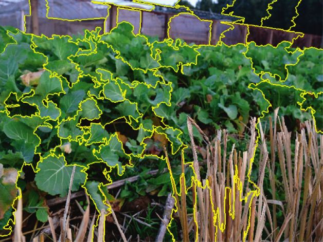
Journal of Electrical and Computer Engineering 7

 (a) (b)

 (c) (d)

 (e) (f)

Figure 6: Algorithm test results. (a) The RGB image captured by Nikon D7500. (b) The RGB image captured by RealSense D415. (c) The
feature point matching result. (d) Superpixel segmentation results. (e) The depth map generated by the algorithm in this paper. (f ) Depth
map taken by depth camera.

 The black areas in Figures 5(e) and 5(f ) are both depth- camera can be fitted according to the position mapping
missing areas. By comparing the two figures, it can be found relationship between the two cameras, while the high res-
that the depth map (f ) automatically generated by the depth olution of the original camera can be retained. In order to
camera is relatively complete, with only a small area of depth verify the scalability of this method, the following two ad-
missing on both sides of the image, while the algorithm in ditional groups of experiments were conducted for
this paper has more missing depth areas, which are mainly verification.
distributed around the image. There are two main reasons The first group of experiments: the industrial camera
for the lack of depth in this algorithm: One is that although used in this system was replaced with Nikon D7500, a
the industrial camera and the depth camera are closely common hand-held SLR camera, and the RealSense camera
connected to each other, they are still not completely still used D415. The scene is replaced by an outdoor farmland
consistent. The shooting picture is not completely over- environment, which has problems such as texture similarity
lapped, which will result in a lack of depth around them. The and occlusion. It is difficult for traditional binocular stereo
second is that some areas are relatively smooth and lack vision to generate a dense depth map through algorithm.
feature points, which may occur in the middle and around Using the method designed in this paper, the results are
the image. By analyzing the results in Figure 5(e), except for shown in Figure 6:
a few depth-missing areas, the results of other depth areas The second group of experiments: the industrial camera
are relatively good, which can basically describe the distance used in this system was replaced with an ordinary mobile
difference between the target and the camera. phone, and the RealSense camera was replaced with model
 The main innovation of the method of obtaining the D435. The scene is also a complex outdoor farmland en-
depth map of the monocular camera proposed in this paper vironment. The method designed in this paper is adopted,
is that a RealSense camera is directly installed close to the and the result is shown in Figure 7:
original monocular camera without replacing the original The results in Figures 6 and 7 show that the method used
hardware system, and the depth map of the monocular to obtain the depth map in this paper has high scalability.

8 Journal of Electrical and Computer Engineering

 (a) (b)

 (c) (d)

 (e) (f )

Figure 7: Algorithm test results. (a) The RGB image captured by mobile phone. (b) The RGB image captured by RealSense D435. (c) The
feature point matching result. (d) Superpixel segmentation results. (e) The depth map generated by the algorithm in this paper. (f ) Depth
map taken by depth camera.
Industrial cameras, SLR cameras, mobile phones, and other environments separately, and the experiment proves that the
photographic devices can be used to obtain high-resolution method has good validity and scalability. Compared with the
RGB images. Both the RealSense D415 and D435 models can existing depth information acquisition methods, the char-
be used to assist in generating the depth maps corresponding acteristics and advantages of this method are as follows:
to the RGB images of the above monocular cameras. It can
 (1) Compared with the traditional active method, al-
be used in various indoor or outdoor scenes. In fact, the
 though this method also requires additional hard-
method proposed in this paper aims to directly transform
 ware equipment, the cost is lower. More importantly,
the existing monocular camera system with the help of
 the system retains the performance of the original
simple hardware equipment at a lower cost so that it has the
 monocular camera, so the RGB images obtained by
function of depth information acquisition, and adds a spatial
 this system have a higher resolution.
dimension to the traditional monocular image detection
system, so as to better understand the scene. (2) Compared with the traditional passive method, this
 method has lower requirements on the location of
4. Conclusion the hardware, as long as the two cameras are closely
 connected to each other and no complicated camera
This paper provides a depth map fitting method for the calibration process is needed. In addition, due to the
existing monocular image or video detection system by assistance of the depth map of the depth camera, this
combining the ideas of active and passive depth map ac- paper only needs a relatively simple algorithm to
quisition methods. By using this method, any single-camera restore the point-to-point depth map corresponding
detection system can be upgraded online. Under the premise to the original monocular camera.
of not changing the original system, the depth information
of the original single camera can be obtained by adding low- Data Availability
cost hardware and combining it with a simpler algorithm so
as to realize the effective utilization of resources. Different The data used to support the findings of this study are in-
hardware is used to test the method in different cluded within the article.
Journal of Electrical and Computer Engineering 9

Conflicts of Interest [13] M. Yao, W. B. Ouyang, and B. G. Xu, “Hybrid cost aggre-
 gation for dense stereo matching,” Multimedia Tools and
The authors declare that they have no conflicts of interest. Applications, vol. 79, no. 31-32, pp. 23189–23202, 2020.
 [14] P. Rogister, R. Benosman, S. H. Ieng, P. Lichtsteiner, and
 T. Delbruck, “Asynchronous event-based binocular stereo
Acknowledgments matching,” IEEE Transactions on Neural Networks and
 Learning Systems, vol. 23, no. 2, pp. 347–353, 2012.
The authors gratefully acknowledge the financial support [15] Y. Ming, X. Meng, C. Fan, and H. Yu, “Deep learning for
provided by the Key Project of Science and Technology monocular depth estimation: a review,” Neurocomputing,
Research Plan of Hubei Provincial Department of Education vol. 438, pp. 14–33, 2021.
(D20192701) and the Hubei Provincial Education Research [16] D. Eigen and R. Fergus, “Predicting depth, surface normals
Project (T201716). and semantic labels with a common multi-scale convolutional
 architecture,” in Proceedings of the IEEE International Con-
 ference on Computer Vision (ICCV 2015), pp. 2650–2658,
References Santiago, Chile, February 2015.
 [17] A. Gordon, H. H. Li, R. Jonschkowski, and A. Angelova,
 [1] W. K. Jia, Y. Zhang, J. Lian, Y. J. Zheng, D. A. Zhao, and “Depth from videos in the wild: unsupervised monocular
 C. J. Li, “Apple harvesting robot under information tech- depth learning from unknown cameras,” in Proceedings of the
 nology: a review,” International Journal of Advanced Robotic IEEE International Conference on Computer Vision (ICCV
 Systems, vol. 17, no. 3, 2020. 2019), pp. 8976–8985, Seoul, South Korea, October 2019.
 [2] Y. F. Hong and J. P. Tan, “Trajectory planning of a planar [18] H. Fu, M. M. Gong, C. H. Wang, K. Batmanghelich, and
 cable-driven robot for industrial detection,” Journal of Physics D. C. Tao, “Deep ordinal regression network for monocular
 Conference Series, vol. 1570, no. 1, 2020. depth estimation,” in Proceedings of the IEEE Computer So-
 [3] T. Ginoya, Y. Maddahi, and K. Zareinia, “A historical review ciety Conference on Computer Vision and Pattern Recognition
 of medical robotic platforms,” Journal of Robotics, vol. 2021, (CVPR 2018), pp. 2002–2011, Salt Lake City, USA, June 2018.
 Article ID 6640031, 13 pages, 2021. [19] Y. R. Chen, H. T. Zhao, Z. W. Hu, and J. C. Peng, “Attention-
 [4] Y. F. Cai, K. S. Tai, H. Wang, Y. C. Li, and L. Chen, “Research based context aggregation network for monocular depth
 on behavior recognition algorithm of surrounding vehicles for estimation,” International Journal of Machine Learning and
 driverless car,” Qiche Gongcheng/Automotive Engineering, Cybernetics, vol. 11, pp. 1–14, 2021.
 vol. 42, no. 11, pp. 1464–1472, 2020. [20] R. D. Mendes, E. G. Ribeiro, N. D. Rosa, and V. Grassi, “On
 [5] C. Guo, M. Y. Wang, K. F. Gao, J. N. Liu, and W. W. Zuo, deep learning techniques to boost monocular depth estima-
 “Location-based service technologies for major public health tion for autonomous navigation,” Robotics and Autonomous
 events: illustrated by the cases of COVID-19 epidemic,” Systems, vol. 136, Article ID 103701, 2021.
 Wuhan Daxue Xuebao (Xinxi Kexue Ban)/Geomatics and [21] G. R. Bradski and A. Kaehler A, Learning OpenCV, Oreilly
 Information Science of Wuhan University, vol. 46, no. 2, Media, Newton, MA, USA, 2018.
 pp. 150–158, 2021. [22] R. Achanta, A. Shaji, K. Smith, A. Lucchi, P. Fua, and
 [6] F. Hsiao and P. Lee, “Autonomous indoor passageway finding S. Süsstrunk, “SLIC superpixels compared to state-of-the-art
 using 3D scene Reconstruction with stereo vision,” Journal of superpixel methods,” IEEE Transactions on Pattern Analysis
 Aeronautics, Astronautics and Aviation, vol. 52, no. 4, and Machine Intelligence, vol. 34, no. 11, pp. 2274–2282, 2012.
 pp. 361–370, 2020.
 [7] H. J. Issaq, T. D. Veenstra, T. P. Conrads, and D. Felschow,
 “The seldi-tof ms approach to proteomics: protein profiling
 and biomarker identification,” Biochemical and Biophysical
 Research Communications, vol. 292, no. 3, pp. 587–592, 2002.
 [8] H. Nguyen, Y. Z. Wang, and Z. Y. Wang, “Single-shot 3d
 shape reconstruction using structured light and deep con-
 volutional neural networks,” Sensors (Switzerland), vol. 20,
 no. 13, pp. 1–13, 2020.
 [9] M. Tolgyessy, M. Dekan, L. Chovanec, and P. Hubinsky,
 “Evaluation of the azure Kinect and its comparison to Kinect
 V1 and Kinect V2,” Sensors, vol. 21, no. 2, pp. 1–25, 2021.
[10] L. Chen, Y. He, J. Chen, Q. Li, and Q. Zou, “Transforming a 3-
 D LiDAR point cloud into a 2-D dense depth map through a
 parameter self-adaptive framework,” IEEE Transactions on
 Intelligent Transportation Systems, vol. 18, no. 1, pp. 165–176,
 2017.
[11] G. Q. Chen, Z. Z. Mao, H. L. Yi et al., “Pedestrian detection
 based on panoramic depth map transformed from 3d-lidar
 data,” Periodica Polytechnica Electrical Engineering and
 Computer Science, vol. 64, no. 3, pp. 274–285, 2020.
[12] W.-P. Ma, W.-X. Li, and P.-X. Cao, “Binocular vision object
 positioning method for robots based on coarse-fine stereo
 matching,” International Journal of Automation and Com-
 puting, vol. 17, no. 4, pp. 562–571, 2020.

You can also read