MODEL COVERED: Effective August 2021 This guide supersedes all previous versions 3842 Redman Drive Fort Collins, CO 80524 - Command Light
←
→
Page content transcription
If your browser does not render page correctly, please read the page content below
Effective August 2021
                         This guide supersedes all previous versions

3842 Redman Drive                  MODEL COVERED:                             1-800-797-7974
Fort Collins, CO 80524                KL408D                           www.CommandLight.com
KNIGHT2

                     THANK YOU
Please allow us to express a simple thank you for investing in a COMMAND LIGHT product.
 As a company, we are dedicated to producing the very best and most versatile flood lighting
 package available. We take great pride in the quality of our work and hope that you will find
                  many years of satisfaction from the use of this equipment.

    Should you have any problems with your product please do not hesitate to contact us.

                                                       3842 Redman Drive
                                                       Fort Collins, CO 80524

                                                       PHONE: 1-800-797-7974
                                                       FAX: 1-970-297-7099
                                                       WEB: www.CommandLight.com

                                              1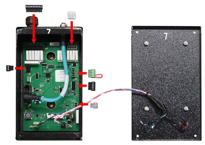
USER GUIDE

             2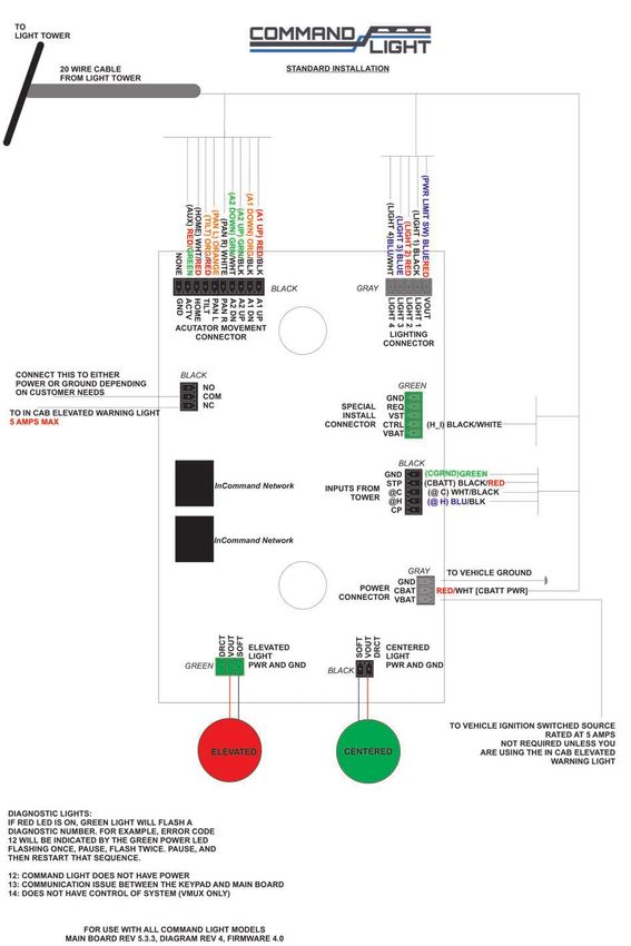
KNIGHT2
Please take the time to read this manual before installing or operating the
COMMAND LIGHT KNIGHT2.
Save this guide for future reference.
Contents
Warranty...................................................................................................................................................... 4
Breakage or Damage During Shipment.................................................................................................... 5
Product Safety Precautions........................................................................................................................ 6
General Description and Specifications.................................................................................................... 7
Operation..................................................................................................................................................... 8
Raising the light from the nested position........................................................................................... 8
Returning the light to the nested position............................................................................................ 9
Autopark Sequence.............................................................................................................................. 9
Installation................................................................................................................................................. 10
Installation Kit................................................................................................................................... 10
Tools Required................................................................................................................................... 10
Installation Notes............................................................................................................................... 10
Location Requirements...................................................................................................................... 11
Mounting........................................................................................................................................... 12
Holster Mounting.............................................................................................................................. 12
Electrical Wiring....................................................................................................................................... 13
12 VDC.............................................................................................................................................. 13
Holster Wiring................................................................................................................................... 13
Warning Device Installation.............................................................................................................. 14
Maintenance.............................................................................................................................................. 15
Cleaning............................................................................................................................................. 15
Center Switch Adjustment................................................................................................................. 15
Rotation Belt Adjustment.................................................................................................................. 16
Power Failure............................................................................................................................................ 17
Rotate to center.................................................................................................................................. 17
Retract the upper stage...................................................................................................................... 17
Retract the lower stage...................................................................................................................... 17
Without tools..................................................................................................................................... 18
Troubleshooting......................................................................................................................................... 19
Error Codes on Holster Circuit Board.................................................................................................... 20
Technical Specifications – Standard DC Models (408D)....................................................................... 21
Specifications..................................................................................................................................... 22
Parts Lists - Exploded Views.................................................................................................................... 23
Exploded View (Base)..................................................................................................................24-25
Exploded View (Midplate)...........................................................................................................26-27
Exploded View (Lamp Tree)........................................................................................................28-29
Exploded View (Backlight)..........................................................................................................30-31
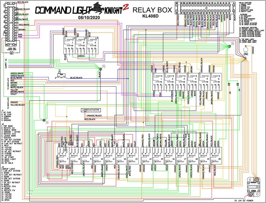
Relay Box.....................................................................................................................................32-34
Wiring Schematics.................................................................................................................................... 35
Relay Box.......................................................................................................................................... 35
Holster Box...................................................................................................................................36-37
OPS Wireless Controller (VMUX/Wireless Systems)...................................................................... 38
Lamp Tree.......................................................................................................................................... 39
3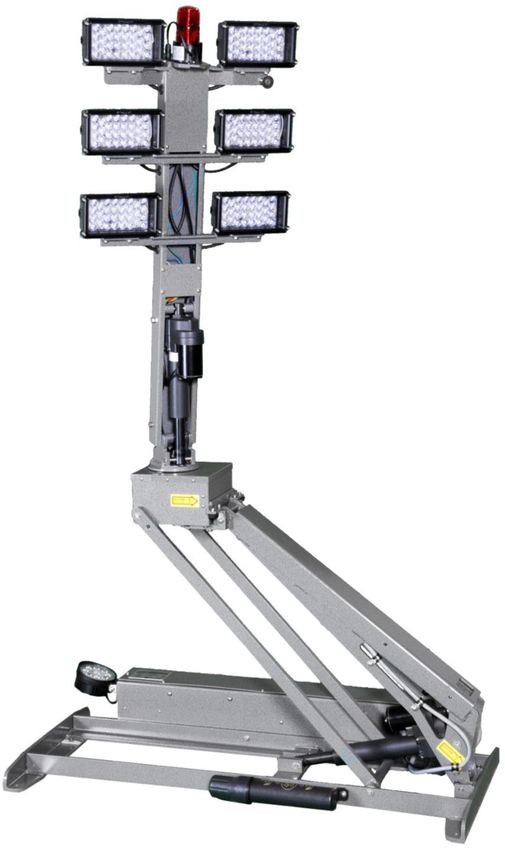
USER GUIDE

               Command Light 			                        PHONE:           1-800-797-7974
               3842 Redman Drive			                     FAX: 		          1-970-297-7099
               Fort Collins, CO 80524		                 WEB: 		          www.CommandLight.com

               COMMAND LIGHT 5 YEAR LIMITED WARRANTY
      COMMAND LIGHT products* come with an industry leading 5-year warranty against any defects in
      materials and workmanship when used and operated for a period of five years. The responsibility of
      COMMAND LIGHT under this limited warranty is limited to the repair and replacement of parts found
      to be defective by COMMAND LIGHT.

      Any parts damaged in shipping or by improper installation, overloading, abuse, or accident of any type
      or cause are not covered by this warranty. If equipment has been damaged in transit, a claim should be
      made against the carrier within three days, as we assume no responsibility for such damage.

      If during this time period, you have any malfunctions not related to misuse, accident, neglect, or normal
      wear and tear, please take the following steps in order to have your light tower serviced under the
      COMMAND LIGHT warranty.

      1. Contact us immediately for initial diagnosis at info@commandlight.com or 800-797-7974; or if
      parts are needed contact parts@commandlight.com.

      2. You will need to have immediate access to the light tower and the serial number. This process can
      be done by individuals with little mechanical ability. (Involves pushing buttons and telling us what the
      light tower is doing or not doing)

      3. We then send parts (if needed) and have an authorized technician dispatched (if needed) with a
      written work authorization number and a base number of hours allotted to do repair. Hourly rates for
      service are to be determined at the time of authorization by COMMAND LIGHT, travel time is paid at
      a maximum of 50% of the authorized service rate.

      4. We remain available for service support via phone, email, or video conference while the technician
      completes the repair, also to extend the original time allotted if additional issues arise. Immediate
      support cannot be guaranteed unless a time is scheduled prior to service.

      5. Let us know when the repair is completed and reference the work authorization number. Email
      an invoice to info@commandlight.com or parts@commandlight.com. If you are unable to create an
      invoice email us for instructions for payment. Make sure any parts we have requested to be returned
      have been shipped back to the provided shipping address. If a return label is issued it must be used.

                                                         4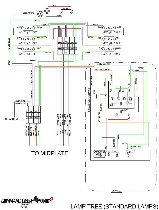
KNIGHT2

 6. Finally, we will pay by mailing a check or crediting the account of the person, department, or
 company doing the repair. Payments will not be made until all requested parts have been returned.

 Please contact us as soon as problems arise in order to execute our warranty. We must have knowledge
 of the issue and provide a work authorization in order to pay or reimburse labor or travel time.

 Any unauthorized service voids this warranty. No work is authorized until written consent is provided
 by COMMAND LIGHT.

 Contact Us Early — before any work is done — We’d love to help!

 *Excludes light producing components (bulbs, lasers, LEDs) These components may come with their
 own manufacturer warranty. Contact us and we can help get it.

Breakage or Damage During Shipment
 The transportation company is fully responsible for all shipping damage and will resolve problems
 promptly if you handle it correctly. Please read these instructions carefully.

 Examine the contents of all shipping cases. If you find any damage, call your transportation agent at
 once and have them make a description on the freight or express bill describing the damage and the
 number of pieces. Then contact us and we will send you the original bill of lading. Also promptly
 contact the transportation company and follow their procedure for filing a claim. Each company will
 have a unique procedure to follow.

 Please note, we cannot and will not enter claims for damages. If we filed a claim here, it would be sent
 to your local freight agent for verification and investigation. This time can be saved by you filing the
 claim directly. Every consignee is on the ground floor, in contact with the local agent who inspects the
 damaged goods, and thus, each claim can be given individual attention.

 Since our goods are packed to comply with the regulations of all railroad, truck, and express companies,
 we cannot allow deduction from any invoice because of any damage, however, be sure to file your
 claim promptly. Our goods are sold F.O.B. factory. We take receipt from the transportation company
 certifying that the goods were delivered to them in good order and our responsibility ceases.

 It is seldom that any breakage or damage occurs in any of our shipments and in no case will the
 customer be out any expense if they follow the above instructions.

 Be sure to keep all damaged goods subject to examination of the truck or express company
 inspector, who may call on you sometime later. These damaged goods, of course, will belong to
 them, and they will inform you what to do with them. If you dispose of these damaged goods,
 your claim may not be paid.

                                                    5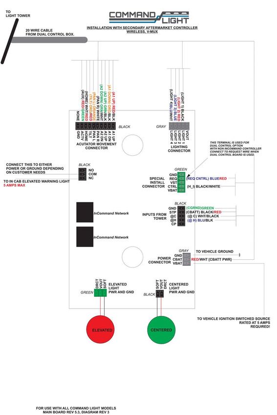
KNIGHT2

Product Safety Precautions
[   Never operate the COMMAND LIGHT
    KNIGHT2 near overhead high voltage power
    lines. The COMMAND LIGHT KNIGHT2 is
    manufactured from electrically conductive
    materials.

[   Do not use the COMMAND LIGHT KNIGHT2
    for uses other than its intended purpose.

[   Do not move emergency vehicle with the light
    extended. Visually verify that the light is
       completely nested before moving vehicle.

[   Do not change light position while people are located within its operating envelope. There are
    numerous pinch points that can cause serious bodily injury.

[   Do not use a high-pressure washer or subject the light to high volumes of water when cleaning.

[   Never use the COMMAND LIGHT KNIGHT2 as a lifting device or mobile arm.

[   Do not use a COMMAND LIGHT KNIGHT2 that has been damaged or is not fully functional,
    including non-working indicator lamps.

[   Never hold any part of the COMMAND LIGHT KNIGHT2 with a hand or foot while it is in
    motion.

[   The COMMAND LIGHT KNIGHT2 has numerous pinch points. Keep loose clothing, hands and
    feet clear of moving parts.

                                                   6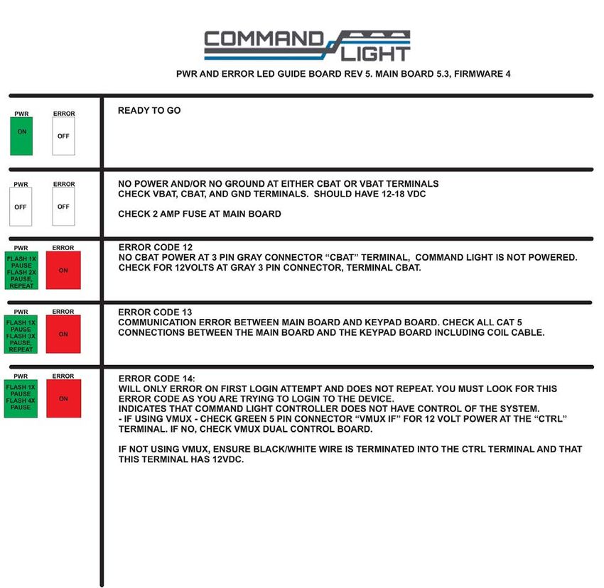
USER GUIDE

     General Description and Specifications
      The KNIGHT2 is designed to provide high intensity emergency scene lighting with quick precision. As
      with any electromechanical device, take precautionary steps to ensure safe operation.

     Never operate the KNIGHT2 near overhead power lines.

     There are several standard lighting options available for the KNIGHT2.

      		           Model #         Description     Minimum Power Requirements
      		 KL408D                     4 x LED        50 Amps, 12 VDC

      The emergency vehicle generator provides power for the 12 VDC circuitry. The umbilical corded
      control unit is powered via 12 VDC eliminating hazardous voltage levels within the hand held
      control box.

      The KNIGHT2 is manufactured to provide years of service with a minimum of maintenance.

                                                      7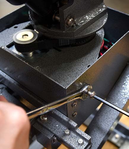
KNIGHT2

Operation
Raising the light from the nested position
 Using the control box, raise the lower or upper stage. You may also activate both stages simultaneously.
 Control switches are of momentary action style and must be held in the “on” position to actuate the
 stages.

 The KNIGHT2 has an override system that precludes rotation of the upper stage until the lower stage
 has elevated approximately 16" from the nested position. When the lower stage is below 16" the
 following conditions exist:

       • Upper stage is prevented from rotating.
       • All lights are turned off, including strobe light if equipped, regardless of light switch positions.
       • Prevents the upper stage from moving down if upper stage is not centered.

 If the supply from the generator is marginal, position the KNIGHT2 before turning on lights.

                                                     8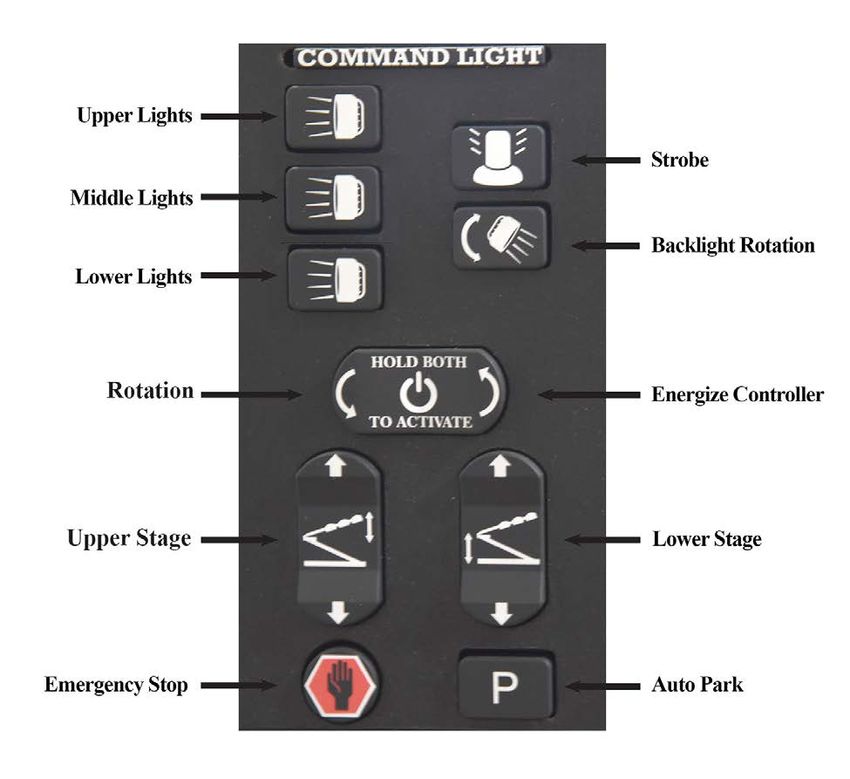
USER GUIDE

     Returning the light to the nested position

       The KNIGHT2 is equipped with an Autopark function as a standard feature. The “P” button on the
       control box initiates the Autopark sequence. Once initiated, the “Emergency Stop”      button indicator
       is illuminated. Pressing the “Emergency Stop”       button will cancel the Autopark sequence.

     Autopark Sequence
       Press green button on the controller once. It does not need to be held in position. The Autopark
       sequence begins:

     1. “Emergency Stop”         light is illuminated.

     2. Lamps are extinguished.

     3. Upper stage begins rotation to the center position. If equipped with back light option, back light
        begins oscillation and returns to the home position.

     4. Once upper stage is centered, rotation stops, lower stage begins retracting.

     5. After lower stage has fully retracted, upper stage begins retracting. Upon upper stage retracting fully,
        “Emergency Stop”         light turns off.

                                                          9
KNIGHT2
Installation
The KNIGHT2 must be installed by a designated installation facility by qualified personnel only. All
safety precautions must be thoroughly understood before installation. Please consult the factory for
additional installation information assistance.
Installation Kit
Included with the KNIGHT2 is an installation kit. Verify that the kit contains the following items:
(1) 50 feet of 2GA-2 Conductor power cable (1) 50 feet of 22GA-20 conductor cable
(1) Pre-wired HOLSTER BOX w/cover (1) Handheld Controller
(1) Small hardware parts bag with:
(4) mounting spacers (4) 5∕16-18 x 2 ½" bolts
(4) 5∕16-18" nylon lock nuts (8) 5∕16" flat washers
(4) large diameter flat washers (2) ¼-20 x 5∕8" Phillips pan head machine screws
(4) ¼" flat washers (2) ¼-20 nylon lock nuts
(3) ½" 90° sealing connector w/nut (1) 1” 90° sealing connector w/ nut
Tools Required
Lifting device (crane, forklift, block and tackle, etc.)
Sling for lifting
Drill
21/64", 17/64" drill bits
Hole punch for metal with 7/8" and 15/16" diameter capacity
Phillips head screwdriver, #2
Command Light flat blade screwdriver (included with light)
7/16" and 1/2" combination wrenches and/or ratchet and 7/16" and 1/2" sockets
8" adjustable wrench
Tongue and Groove Pliers
Wire stripper or razor blade knife
Solder-less wire connector crimp tool
Silicone based gasket sealer, RTV™ recommended
Installation Notes
The KNIGHT2 weighs approximately 165 pounds. Use mechanical assistance to lift the light into
installation position such as a forklift or crane.
Use the provided fender washers under the mounting surface to distribute the weight load evenly.
When routing the connecting electrical wires take care to avoid sharp bends, hot components or other
hazards to the wire.
The KNIGHT2 is not designed to be operated in a raised position while the vehicle is in motion. The
KNIGHT2 includes warning circuit wiring to enable a warning device.
10USER GUIDE
Location Requirements
The standard KNIGHT2 KL408 models can be mounted on any location that is 47" x 25", additionally
allow for a minimum of 3" of space around the perimeter of the nested tower. The surface should be
flat or have only a slight crown. For a recessed installation, allow for a minimum of 3" of space around
the perimeter of the tower taking into consideration the dimensions of the tower both fully nested and
fully elevated. Consult with factory before construction of recessed installation. Verify all dimensions
before installation to ensure proper operation of light will not infringe on other installed components.
For all other installations refer to the dimensional drawing on page 22 of this guide that represents
your particular model of light. The drawings reflect the dimensions of the “working envelope” of a
typical light tower. Make certain sufficient clearances are incorporated in your installation to allow
for variations (vehicle body flex, environmental conditions, future servicing needs, etc.) If your light
model is not represented, call or email the factory prior to beginning any construction of a recessed
installation.
Four mounting bolt holes are required. Additional holes may be drilled in the frame ends if necessary to
clear obstructions.
Access holes for the power cord cabling should be in close proximity to the relay box access holes on
the light. Installing the cords with a sweeping 90º or 180º bend will provide better results.
The control box holster should be mounted in an area shielded from the weather. Allow a minimum of
10” clearance above the control box holster mounting location for easy access to the controller.
11KNIGHT2
Mounting
Place the provided spacers in the location of the light mounting holes. The spacers may be modified to
conform to the contour of the mounting location.
Remove any obstructions below the mounting surface such as headliners.
Attach any necessary lifting attachments to the KNIGHT2. The center of gravity (balance point) is
slightly behind the lower bank of lights.
Slowly lift the KNIGHT2 and check for balanced lifting. Lower and make any necessary adjustments to
the lift points.
Lift and place the KNIGHT2 into position above the spacers. Before placing the full weight of the unit
on the spacers align spacers with the holes in the end frame castings.
Drill 21/64” holes in the mounting surface using
the end casting holes as a template.
Fasten the light using the provided hardware.
To ensure a weather-tight installation apply a
thin bead of silicone based gasket sealer to the
base of the spacer and underside of bolt head.
Remove any lifting straps and devices from
the
KNIGHT2.
Locate and drill the wire feed holes.
Holster Mounting
Using the holster mount as a template, mark hole locations.
Drill 17/64" mounting holes.
Drill any holes required to route the control cable from the holster to the KNIGHT2 relay box.
Attach the holster to the holster mount with the provided hardware.
12USER GUIDE
Electrical Wiring
Please Note: Detailed internal wiring schematics are located at the back of this user guide.
Run the control wire from the control box holster to the KNIGHT2.
Run the power wire from the breaker box or generator to the KNIGHT2. An 80 Amp breaker is
recommended on DC models.
Make the control connections in the KNIGHT2 relay box.
The Model KL408D series KNIGHT2 comes pre-wired to connect to 12 VDC.
12 VDC
Holster Wiring
Determine if an elevated warning device will be used in conjunction with the light tower. If a warning
device will be used, use the wiring diagram on the next page, otherwise, use the wiring diagram in the
back of the user guide.
After routing the control cable into the holster through the sealing connector, attach individual wires to
the provided connectors and insert the connectors into the proper ports on the circuit board
13KNIGHT2
Warning Device Installation
Tools Required:
• 3
/32" Flathead Screwdriver
• Wire Strippers
• Small Torch or Lighter
Wire the gray 22-20 control cable wires to the small connectors using the wiring schematics provided
on pages 36 and 37. There are 2 different schematics, one is the standard version and the other is the
version for dual control with wireless controllers or V-Mux control. The standard schematic will be used
for V-Mux or any other multiplex system if it is only being used for elevated warning. A V-Mux wiring
schematic and circuit board troubleshooting guide are included.
Detaching & Attaching the Controller
Make sure the tab on the coil cord connector lines up with the slot on the controller connector. Rotate
the coil cord connector clockwise until finger tight. DO NOT use tools to tighten this connector.
14USER GUIDE
Maintenance
Cleaning
The KNIGHT2 is constructed with corrosion resistant aluminum and stainless steel fasteners. To further
enhance corrosion resistance all exposed surfaces receive a powder coated paint finish. To ensure years
of trouble free service periodically clean all external surfaces with a mild detergent solution and a gentle
spray of water. DO NOT USE A HIGH-PRESSURE WASHER, which will force water into sensitive
electric circuitry.
Lamp lenses may be cleaned with any commercially available glass cleaner.
Upper and lower stage actuators are sealed units and do not require adjustment or lubrication. The
actuators have slip-clutches to compensate for minor stroke tolerances at the limits of its travel. The
actuator may produce a ratcheting sound at each end of the stroke which is normal. The actuators should
not be made to ratchet excessively, this can lead to premature actuator clutch failure.
All pivot points on the KNIGHT2 are self-lubricating thermal polymer. Periodic cleaning with a
moisture displacing cleaner and soft bristle brush, without disassembly, to remove accumulated dirt and
debris will minimize wear.
Center Switch Adjustment
WATCH THE VIDEO AT WWW.COMMANDLIGHT.COM/TECHNICAL-VIDEOS/
Caution: For best results, angle of vehicle should be less than 10 degrees.
1. Raise lower section high enough to comfortably work on, and above the set safety limit
(i.e. Lights will turn on), then raise lamp tree to a 45 degree angle.
2. Visually verify the centering cam on the rotation spindle is contacting the roller of the center
switch arm.
3. Ensure that when the point of the centering cam is aligned with the roller of the center switch
arm, there is some play in the center switch arm. Without this play, the switch could be crushed or
damaged during rotation.
4. Rotate off center, then press the auto park button and let light tower proceed through sequence until
the lamp tree is a couple inches above the nested position, hit emergency stop.
5. Visually determine which side the lamp tree will be hitting the lift arm, then lower lamp tree
completely using the motion switch on the handheld controller.
6. Raise lower section above safety limit and to comfortable working height.
7. Make reference marks with a permanent marker on both sides of the cam.
8. Loosen screw on center switch cam slightly.
9. Tap centering cam toward the side that the lamp tree is hitting the lift arm.
10. Fully tighten the screw holding the center switch cam.
11. Raise lamp tree to a 45 degree angle, rotate off center.
12. Repeat steps 4-9 until satisfied with centering of the lamp tree.
13. If it looks like center is now adjusted properly, raise lamp tree to a 45 degree angle, and lower stage
all the way up, press autopark and let it go through the entire sequence.
14. If it is still hitting off center, repeat previous steps.
15. If problems adjusting center still persist you may need to adjust the center switch bracket, or call
Command Light at 1-800-797-7974 for further assistance.
15KNIGHT2
Notes:
• Making a mark next to the cam on the
bottom of the spindle will make judging the
adjustments much easier.
• With the centering cam slightly loose,
it may be easier to adjust its position by
tapping on its edge with the assistance of
a socket driver rather than attempting to
move by hand.
• Having the lamp tree at either extreme of fully up or down, will affect the degree of
centering. Setting center while the lamp tree at a 45 degree angle produces the best results.
If problems persist, please call Command Light at 1-800-797-7974.
Rotation Belt Adjustment / Tightening
WATCH THE VIDEO AT WWW.COMMANDLIGHT.COM/TECHNICAL-VIDEOS/
1. Raise lamp tree 45º and rotate away from
motor to access rotation motor screws.
2. Remove the (4) screws from the front
midplate cover.
3. Loosen, but do not remove, screws that
retain rotation motor.
4. Using a 1/2" wrench, loosen the jam nut on
the belt tensioner bolt. Using a 3/16" Allen
socket tighten the tensioner bolt to 20 inch
pounds. Tighten the jam nut to lock bolt
in place. Use caution to not over tighten
drive belt. Rotate lamp tree 180 degrees to
verify that belt is not too tight. If belt is too
tight, rotation motor noise level will rise
noticeably.
5. Replace the cover before returning light
tower to active service.
16USER GUIDE
Power Failure
The KNIGHT2 can be retracted manually if power to the unit is lost. If power loss is temporary,
reestablishing power may be easier than manually retracting the light.
Note: Disconnect power source from the KNIGHT2 before manual operation.
WATCH THE VIDEO AT WWW.COMMANDLIGHT.COM/TECHNICAL-VIDEOS/
Retract the Upper stage
Locate the black, plastic literature canister mounted
to the side of the base of the tower, it contains a
90-degree 3/16 allen wrench and a 3/8th drive ¼” allen
socket.
Use the 90-degree allen wrench to remove the outer
cover screw on the upper actuator.
Insert the ¼” socket into drive socket in the actuator
gear box and rotate clockwise to retract the ram until
lamp tree is fully lowered.
Replace the cover screw! The actuator may become
damaged if the cover screw is not replaced.
Rotate to Center
Slowly apply pressure to the lamp tree to manually rotate to the centered position. Trying to rotate too
quickly or with too much pressure can break the rotation motor shaft. Be certain that you rotate in the
proper direction; the upper stage can rotate a full 360˚. Generally, you need to rotate the lamp tree in the
direction that requires the least amount of travel in order to reach a centered position.
If manual rotation causes the rotation belt to slip, this is alright if minimized. Excessive slippage on the
belt may cause enough damage for the need of belt replacement.
Retract the Lower Stage
Using the same allen tools as before, remove the cover
screw and retract the ram of the actuator as
far as possible for safe travel back to station or
repair facility.
Be careful not to hit the lower lamps on main electrical
box if your tower has the Backlight option and the lamps are not flush with the fixed lamps.
If needed the Backlight may be rotated back to the home position where it is flush with the fixed lamps.
Slowly apply pressure to the Backlight lamps to manually rotate to the home position. Trying to rotate
too quickly or with too much pressure can break the Backlight motor shaft.
Replace the cover screw on the actuator!
17KNIGHT2
IN THE EVENT THAT ALLEN WRENCHES FOR LOWERING THE TOWER CANNOT BE
FOUND THE TOWER MUST BE LOWERED BY REMOVING THE ACTUATOR MOUNT PINS:
Rotate to center without the lowering tools
Slowly apply pressure to the rotation platform to manually rotate to the centered position. Trying to
rotate the platform too quickly or with too much pressure can break the rotation motor shaft or cause the
toothed drive belt to shear a tooth. The upper stage can be rotated in either direction.
Generally, you need to rotate the platform in the direction that requires the least amount of travel in
order to center the platform.
Retract the lower stage without the lowering tools
Support the Midplate (rotation) assembly with temporary blocking to relieve the tension on the lower
actuator pivot pins.
Using a small flat blade screwdriver or needle-nose pliers,
remove the retaining rings that secure the lower pivot pin
in place.
Use a brass drift punch to remove the pivot pin from the
extension end of the actuator. Avoid using a hardened steel
punch which could peen the end of the shaft thus damaging the
bore within the aluminum pivot blocks.
Note that the light weighs in excess of 100 pounds, use caution.
Apply upward pressure on the main lift arm to remove support blocking then slowly lower the lift arm
allowing the actuator shaft to extend past the lower pivot blocks.
Retract the upper stage without the lowering tools
Support the lamp tree with temporary blocking to relieve the tension on the upper actuator pivot pins.
Using a small flat blade screwdriver or needle-nose pliers, remove the 4 e-clips securing the lower pin
of the upper actuator.
Support the lamp tree. Depending on configuration, the weight
of the lamp tree may exceed 50 lbs. Use a brass drift punch to
remove the pin.
Lift up on lamp tree to remove support blocking. Rotate the
actuator towards the front of the light. The upper stage will not
be completely lowered but should provide ample clearance to
transport the light.
Cushion and secure the actuators and other components as
necessary before transporting.
New retaining rings must be installed before returning light
to service.
18USER GUIDE
Troubleshooting
Problem Possible Cause Solution
Unit will not extend No power to the unit Check power input connections.
Incorrect installation Refer to installation instructions.
Upper stage will not rotate Lower stage not raised above Raise lower stage higher.
safety limit (16" above base)
Rotation motor failure. Consult with factory.
Lights will not illuminate. Lower stage not raised above Raise lower stage higher.
safety limit (16" above base)
Circuit breaker tripped. Check circuit breaker at power
supply.
Lamp filament broken. Replace lamp.
Rotation coasts after switch is Rotation belt is loose. Adjust belt to provide no more
released than ¼” slack
Unit will not nest Upper stage not centered. Raise lower stage higher than
16”. Center upper stage (green
light illuminated)
Unit being operated on a slope Lower lamp tree to horizontal.
>5°. Using a pike pole, hold unit level
while lowering to nest position.
Autopark button must be held in Faulty or stuck nest switch. Check nest switch ground and
to park unit operation. Rubber boot may have
shrunk and is holding in switch.
Water in electronics. Remove moisture from ground
points and electronics. Do not
use a pressure washer to clean
unit.
Upper Actuator & Rotation start Down limit switch stuck or Aluminum plunger which acti-
at the same time damaged. vates down limit switch should
move freely. Verify proper switch
operation.
Wires on back light catching Check for 90 degree sealing con- Contact factory for replacement
nector on lamp tree. part.
No lights or rotation Check safety limit sensor, bad, Contact factory for replacement
etc. part.
Autopark is off Center Center switch out of Refer to instructions on page 15
alignment. and 16.
Popping noise during Back Switch boots stuck, faulty rota- Replace switch boots. Contact
Light Rotation tion relay. factory for replacements parts.
19KNIGHT2 20
USER GUIDE

     Technical Specifications – Standard DC Models (408D)
                    Dimensions (with strobe and ½" mounting spacers) – May vary by model:

                                             Height(Depth)           Length           Width
              Retracted                      12"                     47"              23"
              Extended                       88"                     52"              23"
              Recessed installation          14"                     58"              30" Minimum

      Weight: 165 pounds

      Wiring:
      		      Main Power VDC                 2/2 SO cord		             50' provided
      		      Control wiring		               22/20 PVC Jacketed        50' provided

      Relay protection:
      		 Lights 		Cole-Hersey                                 3055     80 amps
      		 Other electrical Cole-Hersey                         3055     40 amp

      Current Draw / Power Requirements:

                                               Average                   Generator Requirement
                 75 Watt LED                   12 VDC/40 amps            1 kW minimum

                    Lift actuators and rotation motor will cause higher current draw during use.

      Motor Duty Cycle:
      		          (All motors thermally protected, specifications are to thermal relay trip):
      		 Lower stage 1:3 (90 seconds maximum per 5 minute)
      		 Upper stage 1:3 (90 seconds maximum per 5 minute)
      		 Rotation                 5-6 Revolutions

      Motor Speed:
          Lower stage       1.0 inches per minute 12 seconds to full extension
          Upper stage       0.5 inches per minute 12 seconds to full extension
          Rotation          2.75 RPM at lamp tree

      Operation:
      			 Angle of vehicle                           15˚ maximum incline

      Wind load:
      			 Design maximum                             60 mph
      			 Maximum tested                             55 mph

                                                        21
KNIGHT2 22
KNIGHT2

EXPLODED VIEWS
  AND WIRING
  SCHEMATICS

      23
USER GUIDE
Parts List - (Base)
24KNIGHT2
Exploded View - (Base)
25USER GUIDE
Parts List - (Mid-Plate)
26KNIGHT2
Exploded View - (Mid-Plate)
27USER GUIDE
Parts List - (Lamp Tree)
28KNIGHT2
Exploded View - (Lamp Tree)
29USER GUIDE
Parts List - (Backlight)
30KNIGHT2
Exploded View - (Backlight)
31USER GUIDE
Parts List - (Relay Box)
32KNIGHT2
Exploded View - (Relay Box)
33USER GUIDE
34KNIGHT2
Wiring Schematics
35USER GUIDE
Holster Box
36KNIGHT2
Holster Box
37OPS WIRELESS CONTROLLER
CONTROL SPLITTER BOARD
WIRE COLORS AND
ORDER SAME AS
STATION B
BLACK BLACK
STATION A
LIGHT TOWER
STATION B
WHITE WHITE
RED RED
GREEN GREEN
ORANGE ORANGE
BLUE BLUE
WHITE/BLACK WHITE/BLACK
RED/BLACK RED/BLACK
WIRELESS
STANDARD
GREEN/BLACK GREEN/BLACK
ORANGE/BLACK ORANGE/BLACK
38
BLUE/BLACK BLUE/BLACK
BLACK/WHITE OPEN BLACK/WHITE
RED/WHITE OPEN RED/WHITE
GREEN/WHITE GREEN/WHITE
BLUE/WHITE TO CONTROLLER BLUE/WHITE
BLACK/RED BLACK/RED
WHITE/RED WHITE/RED
ORANGE/RED ORANGE/RED
BLUE/RED
TO VMUX
BLUE/RED
RED/GREEN RED/GREEN
ORANGE/GREEN OPEN OPEN OPEN ORANGE/GREEN
SHIELD OPEN OPEN OPEN SHIELD
CHASSIS GROUND
12V IGNITION
USER GUIDEUSER GUIDE
39You can also read