Modul-Connect Display Switch Panel - Owner's Manual - Revision. 1.5 - Modul-System
←
→
Page content transcription
If your browser does not render page correctly, please read the page content below
Modul-Connect Display Switch Panel
                         Owner’s Manual

Revision. 1.5
Revision date: 23 October 2020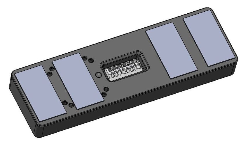
For safe and optimum performance, the Modul-Connect must be used properly. Carefully read and
follow all instructions and guidelines in this manual and give special attention to the CAUTION and
WARNING statements.

                PLEASE KEEP THIS MANUAL FOR FUTURE REFERENCE

Disclaimer
While every precaution has been taken to ensure the accuracy of the contents of this guide,
Modul-System assumes no responsibility for errors or omissions. Note as well that specifications and
product functionality may change without notice.

Important
Please be sure to read and save the entire manual before using your Modul-Connect box and Display
Switch Panel. Misuse may result in damage to the box or switch panels and/or cause harm or serious
injury.

Product Number
24040-03    Modul-Connect Display Switch Panel

Document Part Number
MSDSP 2.0_rev1.5

Service Contact Information
E-mail:       modul-connect@modul-system.com
Phone:        +46 31 746 87 00
Web:          www.modul-system.com

                                                  1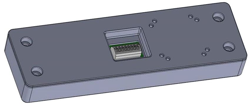
1.          Product description
The 24040-03 Modul-Connect Display Switch Panel includes the items listed below:

   •    Modul-Connect Display Switch Panel
   •    Switch label pack
   •    Switch cover Membrane
   •    Double sided adhesive Switch mounting pad

1.1           Operation
   •    8 off backlit switches (push to operate feedback switches)
   •    OLED display
   •    Navigation switch to scroll between displays and to adjust brightness of the OLED display

The dash display switch panel sends/receives information via Bluetooth High security BLE5.

NOTE! CAN connection will be available in 2021.

2.          Programming the Switch Panel
The dash display switch panel can be set up for its function via the phone APP.

                                                  2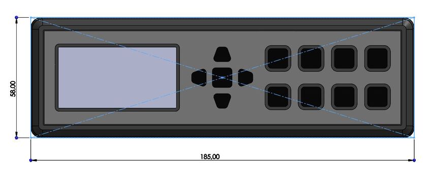
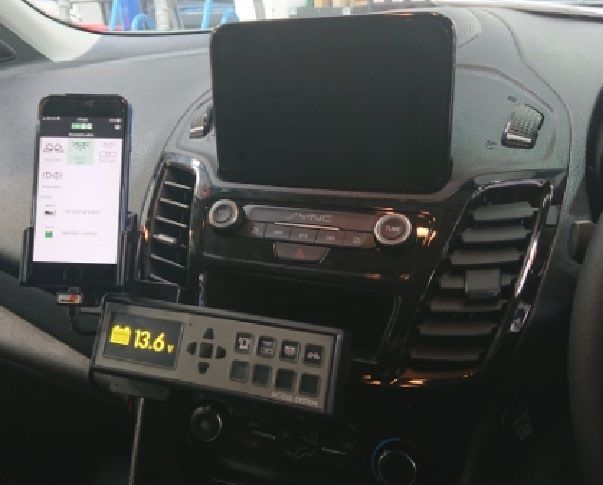
3.           Installation
The 24040-03 Modul-Connect Display Switch Panel is designed to fit in the cab area of the vehicle. It
is currently to be connected via 3 cables and powered from:

    1. +12v (2 amp) Fused supply
    2. Chassis earth
    8. +12v (2 amp) Fused ignition supply

        Connections 1,2 and 8 are currently used and must be connected.
        Connections 3 to 7 are currently unused and must not be connected.

These connections must be made to the rear of the Display Switch Panel and connected via the
8-way WAGO connector. The inputs are set as follows:

 Switch panel    Connection                            Function
 WAGO Pin
 number
      1          +12v Positive supply (Fused 2A)       Power Supply to Display Switch Panel
      2          -12v Negative Chassis earth           Negative Supply to Display Switch Panel
      3          CAN Termination*                      Connect short wire to pin 6 to terminate CAN bus
      4          CAN_L*                                CAN bus connection
      5          CAN_H*                                CAN bus connection
      6          CAN Termination*                      Connect short wire to pin 3 to terminate CAN bus
      7          Digital Input pin 7* (Fused 2A)       Generic 12V input signal for e.g. interior light or ignition
                                                       sense
        8         Digital Input pin 8 (Fused 2A)       Generic 12V input signal for e.g. ignition sense
* Available in 2021

To open the WAGO connector, using a
small flat blade screwdriver, push in the
release button on the top of each
connector.
Use 0.75mm² to 1.0mm² cable for
connections.
Once the wire is inserted into the
connector, remove pressure from the
screwdriver, then test pull the cable to
ensure it is secure.

The WAGO clamp secures the conductor
and encloses its insulation.

                                                                PIN 1         PIN 2         PIN 8
                                                                Battery (+)   GND           Digital input signal

                                                   3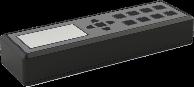
3.1           Mounting
The Modul-Connect Display Switch Panel can be mounted in several ways.

    • Double sided adhesive Switch mounting pad. The thickness of the pad and size lets the
      Display Switch Panel stick to a number of uneven surfaces.

   •   Double sided adhesive Switch mounting pad with DIN Plate. The Display Switch Panel can
       be mounted on a DIN cover plate and placed in a spare DIN position in the cab area of the
       vehicle (Ford Transit, Transit Custom and others).

       DIN mounting blanking plates are available from local car radio suppliers and most Modul-
       Systems workshops.
       1. Ensure the DIN blanking plate fits into the OEM aperture.
       2. Drill the DIN blanking plate to allow connection of the 3 cables to the rear of the Display
           Switch Panel (use the adhesive Switch mounting pad as a position template).
       3. Use the double-sided adhesive Switch mounting pad to attach the Display Switch Panel
           to the DIN blanking plate.

         DIN blanking plate (not supplied):

                                                  4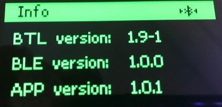
• AMPS mounting. The AMPS pattern can be found on any number of different manufacturers
  shaped mounting devices and cradles.

   The AMPS hole pattern is an industry standard hole configuration. It consists of four holes located
   in a rectangular pattern spaced at 30 mm by 38 mm and attached using M3 fixings.

   On the Display Switch Panel, the AMPS pattern consists of 8 holes. This allows the mounting (not
   supplied) to be fitted in both a horizontal or vertical orientation.

   The AMPS mounting is positioned under the ‘push’ switch panel for robust operation and easier
   installation.

   CAUTION! Maximum M3 screw length is 14mm.
   Care must be taken when selecting the mounting screws to be used. Using screws longer than
   14mm will cause permanent damage to the internal PCB and void any associated warranty.

• ConnectClips. The AMPS mounting points, or the double-sided adhesive switch mounting pad, can
  be fixed to the to a dashboard ConnectClip (available separately for each specific make and model
  of vehicle).

   The ConnectClip is a mounting platform that clips to the dashboard. It serves as a stable base for
   the Display Switch Panel. The installation of the ConnectClip only takes a minute, no special tools
   are required, and you do not need to drill any holes.

   When using a ConnectClip, the Display Switch Panel will always be within comfortably and easy
   reach. It will be placed onto the dashboard instead of the windshield, giving you clear sight. The
   ConnectClip is custom designed for each car model, giving a perfect fit.

   When mounting the Display Switch Panel to the ConnectClip, a vibration support block can be
   required (available separately). This can be cut down to shape and size to support the OLED
   screen end, or switch end of the Display Switch Panel dependent on
   right or left-hand drive.

                                                   5
Right-hand drive shown:

                                                        ConnectClip
                                                      Proclip

                                                       Vibration Support Block
                                                       Vibration  Support Block

3.2           Precautions for The OLED Screen
Although manufactured to be robust in design, and in operation is protected by the Switch cover
Membrane, the OLED display should be treated with an amount of care on installation.

   •   Since the OLED display panel is made of glass, any strong mechanical impact due to falling
       dropping etc, directly to the screen may cause damage (breakage or cracking).
   •   The OLED surface is made of soft material and could be scratched. Please take care when
       handing. If the surface of the OLED module is contaminated before the application of the
       Switch cover Membrane, please wipe it off gently by using moist soft cloth with isopropyl
       alcohol; do not use water, ketone or aromatics.
   •   If there is water on the OLED surface, please wipe it off immediately.
   •   Do not attempt to disassemble the OLED Screen.
   •   Do not leave any physical article on or attached to the OLED Screen surface for an extended
       period of time.

                                                6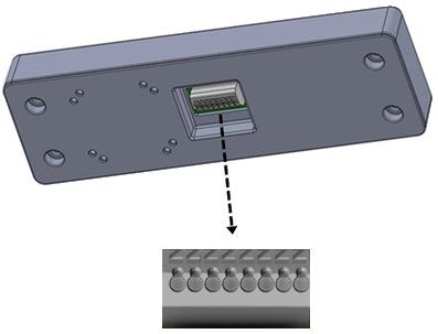
4.          Operation

    1. OLED Display
    2. Navigation Buttons
    3. Accessory switching Buttons

The 5 Navigation Buttons are Up, Down, Right, Left and the Centre is Select.
On powering up the DDS (Dash Display Switch) it shows:

The QR code and serial number screen indicate that the DDS is in Programming Mode.
In Programming Mode, the DDS is discoverable by the APP and can be programed.
The DDS Serial Number and Pin number are displayed for ease of programming.

When programed, the Display will show Battery voltage, Internal PCB temperature and vehicle
weighing (if fitted).

To change between displays, use the 5 Navigation Buttons, Up, Down, Right, Left and the Centre is
Select.

To select the DDS SETTINGS, hold down the Select button for 4 seconds, the display will revert back if
no buttons are pressed for 15 seconds or if the Select button is pressed for 4 seconds.

                                                  7
The DDS SETTINGS menu will look like this:
A box around the icon is the selection and can be moved with the Right and Left Navigation Buttons.

There are currently 4 options,

•   Information – Shows current BTL, BLE and APP versions.

•   Navigation Button Key Sound – Speaker symbol ON - Strikethrough Off.

•   Overweight Alarm - Bell symbol ON - Strikethrough Off.

•   Programming Mode – When selected the DDS will go into Programming Mode.

To exit this Function, hold down the Select button for 4 seconds.

The DDS will Sleep if there is no input or Ignition signal for 60 Seconds.

Any switch input will wake the DDS up again.

Removing power (Pins 1 or2) from the DSS will re-boot it.

                                                    8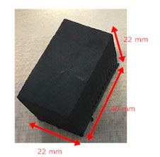
5.             Specifications
Note: The specifications are subject to change without notices.

                     24040-03 Modul-Connect Display Switch Panel
 Operation                        Switch panel with display
 Homologation                     ECE 10R04 | CE (pending)
 IP Rating                        Casing IP 44 Conformally coated PCB IP67
 System Voltage                   9-16 Vdc
 Communication                    -
 Bluetooth                        High security BLE5
 CAN                              Not currently available
 Max operating communication      100m (clear line of sight)
 distance BLE5
 Max internal vehicle operating   8m
 communication distance
 Screen                           128x64 dot matrix OLED
 Wago connectors                  8
 Recommended Viewing Angle        ≥45°
 OLED Operation Life Time         Min 24,000 hours specified as 50% of initial brightness
 Operating Temperature            -40°C to 50°C at full load
 Storage Temperature              -40°C to 100°C
 Weight                           0.15 kg excluding packaging
 Dimensions                       185mm x 58mm x 21.6mm

                                                     9
6. Warranty
THREE YEAR LIMITED WARRANTY
The limited warranty program is the only one that applies to this unit, and it sets forth all the
responsibilities of Modul-System. There is no other warranty, other than those described herein. Any
implied warranty of merchantability of fitness for a particular purpose on this unit is limited in
duration to the duration of this warranty.
This unit is warranted, to the original purchaser only, to be free of defects in materials and
workmanship for three years from the date of purchase without additional charge. The warranty
does not extend to subsequent purchasers or users.
Manufacturer will not be responsible for any amount of damage in excess of the retail purchase price
of the unit under any circumstances. Incidental and consequential damages are specifically excluded
from coverage under this warranty.
This warranty does not apply to damage to units from misuse or incorrect installation/connection.
Misuse includes wiring or connecting to improper polarity power sources.
RETURN/REPAIR POLICY:
If you are experiencing any problems with your unit, please contact our customer service department
at info@modul-system.com or phone +46 31 746 87 00 before returning product. After speaking to a
customer service representative, if products are deemed non-working or malfunctioning, the product
may be returned to Modul-System within 30 days of original purchase. Any defective unit that is
returned to manufacturer within 30 days of the date of purchase will be replaced free of charge.
If such a unit is returned more than 30 days but less than three years from the purchase date,
manufacturer will repair the unit or, at its option, replace it, free of charge. If the unit is repaired,
new or reconditioned replacement parts may be used, at manufacturer’s option. A unit may be
replaced with a new or reconditioned unit of the same or comparable design. The repaired or
replaced unit will then be warranted under these terms for the remainder of the warranty period.
The customer is responsible for the shipping charges on all returned items.
LIMITATIONS:
This warranty does not cover accessories, such as adapters and batteries, damage or defects result
from normal wear and tear (including chips, scratches, abrasions, discoloration or fading due to
usage or exposure to sunlight), accidents, damage during shipping to our service facility, alterations,
unauthorized use or repair, neglect, misuse, abuse, failure to follow instructions for care and
maintenance, fire and flood.
If your problem is not covered by his warranty, contact our Customer Service Department
info@modul-system.com or +46 31 746 87 00 for general information if applicable.
10You can also read