MONTE CARLO SIMULATION OF PHOTONS BACKSCATTERING FROM VARIOUS THICKNESSES OF LEAD LAYERED OVER CONCRETE FOR ENERGIES 0.25-20 MEV USING FLUKA CODE
←
→
Page content transcription
If your browser does not render page correctly, please read the page content below
www.nature.com/scientificreports
OPEN Monte Carlo simulation of photons
backscattering from various
thicknesses of lead layered
over concrete for energies
0.25–20 MeV using FLUKA code
Ihsan A. M. Al‑Affan1*, Mohammad A. Z. Qutub1,2 & Richard P. Hugtenburg1,3
There is an increased interest in determining the photon reflection coefficient for layered systems
consisting of lead (Pb) and concrete. The generation of accurate reflection coefficient data has
implications for many fields, especially radiation protection, industry, and radiotherapy room
design. Therefore, this study aims to calculate the reflection coefficients of photons for various
lead thicknesses covering the concrete. This new data for lead, layered over concrete, supports
various applications, such as an improved design of the mazes used for radiotherapy rooms, which
helps to reduce cost and space requirements. The FLUKA Monte Carlo code was used to calculate
photon reflection coefficients for a concrete wall with different energies. The reflection coefficient
was also calculated for a concrete wall covered by varying thicknesses of lead to study the effect of
lining this metal on the concrete wall. The concrete’s reflection coefficient data were compared to
internationally published data and showed that Monte Carlo calculations differed significantly from
some of the extrapolated data. The absorbed dose of backscattered photons for various thicknesses
of lead covering the ordinary concrete has been tabulated as a function of the reflection angle.
Also, the reflection coefficient as a function of the Pb thicknesses covering the ordinary concrete
has been figured to study the dose reduction factor. The generation of accurate data for reflection
coefficients is vital for many fields, especially for radiation protection and radiotherapy room design.
The new data have been presented for lead layered over concrete in various applications, such as an
improvement in the design of the mazes used for radiotherapy rooms, thereby reducing the cost and
space requirements. In addition, the Monte Carlo method enables calculating the energy distribution
of reflected photons, and these were shown for a range of angles.
Data for backscattered photons from various materials are essential for shielding purposes, the quality of which
has implications for many fields, especially radiation protection in industry and radiotherapy room design.
Recent studies by Al-Affan et al.1,2 found a novel technique that can reduce the dose of backscattered photons
at the radiotherapy room’s maze entrance. This technique is based on using a few millimetres of lead to cover
the concrete walls of the maze of a radiotherapy room. Dose rates of backscattering photons from radiotherapy
rooms walls, floors and passageways can be equal or even exceed the dose rate of transmission photons through
the room w alls3–6.
Therefore, a knowledge of backscattering photons is important to reduce the radiation risks of passers-by
and staff working near the treatment room. The concept of backscattering photons can be defined in terms of
hiteness7,8. This term is expressed in a radiation field as the reflected photons’
the Latin word ‘albedo’; that is, w
ratio from the material surface to those incidents on that surface. The albedo concept may also be termed as a
reflection coefficient (RC). The reflected radiation takes into account photons that are backscattered from the
surface and the medium’s various depths. The RC depends on the mean free paths of the photons below the
1
Swansea University, Swansea SA2 8PP, UK. 2Department of Physics, Umm Al-Qura University, Makkah, Saudi
Arabia. 3Department of Medical Physics and Clinical Engineering, Singleton Hospital, Swansea SA2 8QA,
UK. *email: i.al-affan@swansea.ac.uk
Scientific Reports | (2021) 11:18362 | https://doi.org/10.1038/s41598-021-96026-y 1
Vol.:(0123456789)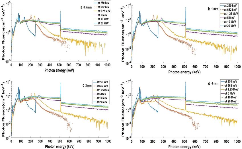
www.nature.com/scientificreports/
reflector surface. A dose albedo is commonly used for practical purposes, defined as the fraction of the incident
dose that the surface reflects at certain a ngles9,10.
The Compton equation and the Klein–Nishina formulae were the early studies for the backscattered radia-
tion in 1929, which led to a general expression for scattering and collisions of cross-sections of photons and
electrons11,12. Hayward and Hubble studied Cobalt-60 (Co60) photon energy distributions as a function of the
backscattered angles in 1954. However, the early comprehensive study of backscattering was given by H yodo13,
where the method of a scintillation spectrometer and the point gamma sources of C o and caesium-137 ( Cs137)
60
were used. Fujita et al. and Mizukami et al. arrived at an empirical formula of variation of photon backscattered
values’ number and energy by increasing the thickness of the scattered slab14,15. Their work proved that more
than two mean free paths of the radiation source are enough to make the reflected material as infinite thickness.
Photon backscattering has already been the subject of numerous measurements and Monte Carlo
calculations16–22. These studies concern the backscattering of various photon energies with different methods
show almost similar results. However, the differential dose of backscattered photons for concrete at various
angles, for bremsstrahlung and mono-energetic photons, have been tabulated in NCRP23. These values of the
photon reflection coefficient are based on the evaluation of data from NCRP23, and Lo24. Furthermore, in the
NCRP23, the reported uncertainty of the reflection coefficient values was on the order of ± 50% due to both the
interpolations and the calculations.
In this research article, because ordinary concrete has a wide application as a radiation shielding material,
simulations with FLUKA MC code was used to establish the possibility of introducing the ordinary concrete
dose of backscattered photons for different mono-energetic incident photons. Then, the dose of backscattered
photons of ordinary concrete covered with various thicknesses of lead is simulated. The photon beams would
normally be incident on the target, and the energy range is between 250 keV to several MeV at various angles of
the reflected beam. The relationship between the reflection coefficient (RC) and the thickness of the lead cover-
ing the ordinary concrete has been studied. The aim is to investigate the influence of various thicknesses of lead
covering ordinary concrete. Also, the optimised thickness of lead for various incident photon energies has been
calculated, which gives a maximum reduction of the backscattered photons dose. This research has produced
detailed calculations for the backscattered dose over a wide range of angles. The dosemeter in this work is thin
enough to minimally perturb the photons and thick enough to offer electronic equilibrium. In previous work,
an average dose was calculated with a relatively larger dosemeter. Furthermore, the reflection coefficient was not
calculated or measured before for a multi layered materials.
Methods
The FLUKA Monte Carlo code, installed on a Linux Ubuntu operating system, an Intel CORE i7 desktop com-
puter, and a High-Performance Computer (HPC Wales) were used to carry out the simulations. A code input file
involves the radiation source and its energy, the beam’s position, the materials, geometry, the number of primary
photons, and their properties. A region that holds the whole system of radiation source and geometry is known
as ‘the void’ surrounded by a ‘black-hole’ region. All the radiations that reach the black-hole would disappear
because it has an infinite absorption cross-section. The geometry used in the simulations consists of different
energy sources, water dosimeters and reflected materials. The photon energy cut-off was set to 1 keV, and the
electron kinetic energy cut-off was set to 100 keV. Rayleigh scattering was taken into a ccount25,26.
Flair is an integrated development environment for FLUKA; it uses a friendly interface to facilitate editing
les26,27. A card is a keyword followed by a list of arguments. Below is a brief
input files and imaging the output fi
description of some of the most fundamental cards that are used in this work:
Primary Cards involve BEAM and BEAMPOS cards. A Beam Card defines the characteristics of a radiation
beam with an arbitrary distribution of energy. BEAMPOS defines the position and direction of the radiation
beam.
Geometry Cards: these cards allow the user to define the complex geometries that can be shown by graphical
tools. There are multiple card options under the geometry elements, such as rectangular parallelepipeds (RPP)
that are considered as a region. Then each region needs to assign its materials.
Media Cards: these cards are used to define different materials such as concrete for walls, water for the target
and the dosimeters and air for the environment, etc.
Scoring Cards: there are several cards to score particles that pass through the dosimeters. The details of all
cards above are discussed in the FLUKA m anual28.
Dose calculations (Do ) for various energies of incident photon beam at reflected materi‑
als. The FLUKA code was used to simulate the source that is a conically diverged photon beam with a 5.65 cm
radius at the reflected material surface, giving an equivalent area of 10 × 10 cm2 field size (Fig. 1). The photon
source was fixed at 100 cm from the surface of the rectangular parallelepiped water phantom. Inside the phan-
tom, several dosimeters were simulated at various depths along the central axis. The dosimeters were rectangular
and made of water, which is a suitable tissue equivalent material. The photons dose was calculated for those
dosimeters inside the phantom. The maximum dose was obtained and considered as the incident dose (Do). The
incident photons had energies of (0.25, 0.5, 0.662, 1, 1.25, 3, 7, 10, 15, and 20 MeV) to study several components
of the X-ray spectrum usually present in the primary beam (of energies up to 20 MeV). The high energy is used
for applications on big patients where the cancer is deep in the body.
Reflection coefficients (RC) of photon beams. The entire geometry of backscattered photons simula-
tion was surrounded by a large sphere of a void of 1000 cm in a radius of vacuum, and this was surrounded by
a larger sphere of a black-hole of 10,000 cm in r adius25. The main reason for using vacuum was to avoid photon
Scientific Reports | (2021) 11:18362 | https://doi.org/10.1038/s41598-021-96026-y 2
Vol:.(1234567890)www.nature.com/scientificreports/
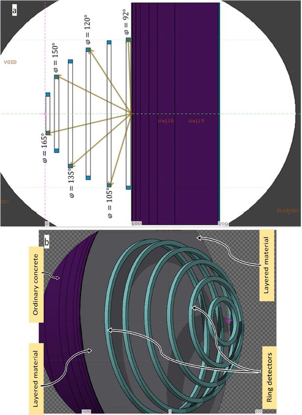
Figure 1. FLUKA Monte Carlo simulation of the ring dosimeters to calculate the dose of backscattered photons
at reflection angles with respect to the incident trajectory, normal to the surface (a: is 2D and b: 3D image).
Scientific Reports | (2021) 11:18362 | https://doi.org/10.1038/s41598-021-96026-y 3
Vol.:(0123456789)www.nature.com/scientificreports/
Angle of reflection or scatter (degrees) from
surface of concrete
Energy (MeV) 92 105 120 135 150 165
0.25 1.21 10.49 18.02 23.01 26.29 28.03
0.5 0.80 7.24 12.11 15.03 16.74 17.54
0.662 0.66 5.99 9.95 12.29 13.56 14.12
1 0.45 4.15 6.83 8.33 9.14 9.45
1.25 0.37 3.47 5.68 6.91 7.57 7.82
2 0.25 2.43 4.00 4.89 5.36 5.55
3 0.19 1.92 3.24 4.02 4.49 4.65
5 0.14 1.58 2.79 3.58 4.04 4.23
7 0.11 1.43 2.62 3.40 3.85 4.06
10 0.09 1.29 2.45 3.23 3.69 3.88
20 0.07 0.98 1.99 2.70 3.11 3.32
Table 1. The reflection coefficient of photons for ordinary concrete as a function of reflected angles calculated
using the FLUKA code (wall-reflection coefficient). Multiply each table entry by 1 0–3 (e.g., the entry 5.39
means 5.39 × 10⁻³) with electrons cut-off = 100 keV and photons cut-off = 1 keV. The statistical uncertainties are
within ± 4% (95% confidence limit).
× 10-3
40
NCRP
(Co-60)
35
Calculated
30 (1.25 MeV)
NCRP
25
(500 keV)
20
RC
Calculated
(500 keV)
15
NCRP
10 (250 keV)
Calculated
5 (250 keV)
0
90 110 130 150 170 190
Reflecon angle (degree)
Figure 2. Comparisons between the backscattered photons of ordinary concrete of NCRP data and FLUKA
calculations as a function of reflection angles (with respect to the incident trajectory, normal to the surface).
scattering in the air, which contaminates the result. The irradiations were carried out for a range of photon
energies. For each photon energy, the FLUKA code was run for five cycles to determine the results’ statistical
fluctuation. Moreover, 70–230 million photon histories were generated for each simulation to get a statistical
uncertainty of better than 4% (95% confidence limit). The computation time of the doses was between 60 and
140 h for five cycles for all situations.
To enhance the dosimeter efficiency and reduce the computation time, ring dosimeters made of water, were
placed at 1 m in the radius of a vacuum semi-spherical object. The source of the incident photon beam was
placed on the top of the sphere surface, the reflected materials were in the sphere center, and the ring dosimeters
positioned at the sphere surface regarding its reflection angles (ϕ) as shown in Fig. 1. The ring dosimeters were
1 cm thick (between the inner and outer circles) and 1 cm in height. This size of dosimeters is capable of inducing
electronic equilibrium and reduces the photons perturbation. The reflection angles with respect to the incident
trajectory, normal to the surface, were taken at 92◦ , 105◦ , 120◦ , 135◦ , 150◦ , and 165◦ as shown in Fig. 1. Using a
Scientific Reports | (2021) 11:18362 | https://doi.org/10.1038/s41598-021-96026-y 4
Vol:.(1234567890)www.nature.com/scientificreports/
Angle of reflection or scatter (degrees) from
surface of concrete
Energy (MeV) 92 105 120 135 150 165
0.2 mm Pb
0.25 0.47 4.37 10.02 14.79 18.14 19.67
0.662 0.28 3.99 7.87 10.61 12.30 12.96
1.25 0.20 2.74 5.15 6.83 7.87 8.21
3 0.15 1.85 3.52 4.78 5.55 5.79
5 0.13 1.65 3.25 4.47 5.21 5.43
7 0.11 1.54 3.05 4.15 4.83 5.05
10 0.09 1.38 2.79 3.77 4.39 4.59
15 0.07 1.19 2.45 3.36 3.86 4.05
20 0.06 1.02 2.13 2.93 3.43 3.61
0.5 mm Pb
0.25 0.33 2.40 5.38 8.32 10.47 11.42
0.662 0.20 2.42 5.27 7.40 8.80 9.33
1.25 0.15 2.00 3.99 5.46 6.37 6.74
3 0.16 1.87 3.73 5.35 6.40 6.78
5 0.15 1.94 4.12 6.13 7.48 7.94
7 0.14 1.88 4.08 6.05 7.40 7.82
10 0.12 1.70 3.71 5.47 6.58 6.95
15 0.09 1.44 3.13 4.51 5.41 5.61
20 0.07 1.22 2.64 3.75 4.46 4.70
1 mm Pb
0.25 0.29 2.02 4.07 6.02 7.44 8.04
0.5 0.16 1.38 3.17 4.77 5.88 6.34
0.662 0.16 1.47 3.31 4.79 5.78 6.07
1 0.08 0.89 1.89 2.65 3.16 3.31
1.25 0.13 1.42 2.95 4.10 4.86 5.09
2 0.15 1.58 3.10 4.34 5.14 5.37
3 0.17 1.79 3.59 5.15 6.24 6.63
5 0.19 2.18 4.61 6.98 8.63 9.24
7 0.19 2.34 5.15 7.92 9.98 10.69
10 0.18 2.30 5.13 7.99 10.02 10.65
15 0.14 1.96 4.43 6.75 8.42 8.98
20 0.11 1.65 3.69 5.53 6.82 7.20
2 mm Pb
0.25 0.29 1.99 3.89 5.69 6.92 7.40
0.5 0.14 1.07 2.14 3.14 3.86 4.08
0.662 0.13 1.05 2.12 3.07 3.70 3.91
1 0.07 0.62 1.27 1.81 2.16 2.25
1.25 0.11 1.04 2.11 2.97 3.55 3.65
2 0.14 1.41 2.71 3.79 4.49 4.70
3 0.17 1.82 3.52 4.97 6.02 6.33
5 0.20 2.39 4.87 7.23 8.94 9.51
7 0.22 2.76 5.77 8.77 11.01 11.65
10 0.24 3.01 6.40 9.83 12.37 13.46
15 0.22 2.88 6.19 9.57 12.12 13.19
20 0.18 2.49 5.36 8.24 10.40 11.25
3 mm Pb
0.25 0.29 1.98 3.90 5.66 6.91 7.42
0.5 0.14 1.05 1.99 2.87 3.50 3.68
0.662 0.13 1.00 1.86 2.65 3.19 3.35
1 0.07 0.57 1.08 1.52 1.82 1.89
1.25 0.11 0.95 1.81 2.59 3.06 3.20
2 0.14 1.39 2.60 3.63 4.31 4.52
3 0.17 1.86 3.57 5.05 6.07 6.42
5 0.21 2.55 5.11 7.48 9.18 9.75
Continued
Scientific Reports | (2021) 11:18362 | https://doi.org/10.1038/s41598-021-96026-y 5
Vol.:(0123456789)www.nature.com/scientificreports/
Angle of reflection or scatter (degrees) from
surface of concrete
Energy (MeV) 92 105 120 135 150 165
7 0.23 3.04 6.13 9.18 11.36 12.12
10 0.26 3.42 6.97 10.47 13.19 14.05
15 0.26 3.52 7.09 10.71 13.48 14.52
20 0.22 3.18 6.44 9.68 12.13 13.17
4 mm Pb
0.25 0.29 1.99 3.90 5.66 6.90 7.42
0.5 0.14 1.04 1.96 2.81 3.41 3.63
0.662 0.13 0.97 1.80 2.55 3.05 3.20
1 0.07 0.55 1.02 1.44 1.70 1.77
1.25 0.11 0.91 1.72 2.41 2.91 2.99
2 0.14 1.39 2.58 3.61 4.29 4.48
3 0.17 1.91 3.64 5.16 6.19 6.55
5 0.21 2.67 5.32 7.73 9.50 10.09
7 0.24 3.23 6.46 9.51 11.82 12.56
10 0.27 3.72 7.40 11.04 13.67 14.66
15 0.27 3.98 7.78 11.42 14.24 15.40
20 0.24 3.73 7.21 10.53 13.18 14.21
6 mm Pb
0.25 0.29 1.99 3.90 5.65 6.91 7.41
0.662 0.13 0.98 1.79 2.50 2.98 3.15
1.25 0.11 0.91 1.67 2.35 2.80 2.93
3 0.17 1.96 3.81 5.42 6.53 6.85
5 0.21 2.83 5.65 8.19 9.96 10.66
7 0.25 3.48 6.93 10.17 12.44 13.24
10 0.28 4.13 8.12 11.86 14.66 15.53
15 0.28 4.58 8.85 12.67 15.61 16.59
20 0.26 4.51 8.43 11.95 14.62 15.64
1 cm Pb
0.25 0.29 1.99 3.89 5.66 6.93 7.42
0.662 0.13 0.97 1.78 2.49 3.01 3.16
1.25 0.11 0.91 1.68 2.35 2.84 2.94
3 0.17 2.02 4.00 5.76 6.93 7.37
5 0.22 2.96 6.03 8.76 10.70 11.45
7 0.25 3.72 7.50 10.96 13.36 14.22
10 0.29 4.55 8.92 12.99 15.87 16.83
15 0.30 5.24 9.96 14.14 17.15 18.40
20 0.28 5.27 9.88 13.67 16.49 17.59
2 cm Pb
0.25 0.29 1.99 3.89 5.67 6.91 7.37
0.662 0.13 0.98 1.77 2.50 2.98 3.18
1.25 0.11 0.91 1.68 2.36 2.87 2.97
3 0.17 2.05 4.12 5.97 7.30 7.78
5 0.22 3.04 6.31 9.24 11.32 12.14
7 0.26 3.85 7.96 11.63 14.31 15.23
10 0.29 4.78 9.64 13.97 17.08 18.26
15 0.31 5.58 10.94 15.56 18.84 20.11
20 0.29 5.70 11.12 15.42 18.56 19.76
Table 2. The reflection coefficient of photons for various Pb thickness layers layered over ordinary concrete
as a function of reflected angles calculated using the FLUKA code (wall-reflection coefficient). Multiply each
table entry by 10–3 (e.g., the entry 5.39 means 5.39 × 10⁻³) with electrons cut-off = 100 keV and photons cut-
off = 1 keV. The statistical uncertainties are within ± 4% (95% confidence limit).
Scientific Reports | (2021) 11:18362 | https://doi.org/10.1038/s41598-021-96026-y 6
Vol:.(1234567890)www.nature.com/scientificreports/
Figure 3. The fluence spectra of backscattered photons of various energy for (a): 0.5 mm, (b): 1 mm, (c): 2 mm,
and (d): 4 mm Pb layered over the ordinary concrete at a reflection angle of 135°.
simulated water dosimeter because water is a tissue equivalent material that directly compared with published
results, including measurements.
The reflection coefficient (RC) can be calculated by the following relationship:
Dϕ
RC = (1)
Do
where (Do ) is the incident dose and Dϕ is the absorbed dose of backscattered photons. The dose can be calcu-
lated from photon energy (E), where the FLUKA code gives the photon energy (E) deposited in the GeV unit25.
Therefore, the dose can be obtained by converting the energy to joules and dividing by the mass of the dosimeter.
FLUKA normalises its dose per incident particle (in this case, it is a photon)25.
Firstly, the RC of an ordinary concrete wall was calculated for the mentioned energies in “Dose calculations
D0 for various energies of incident photon beam at reflected materials” section. The thickness of the reflected
material was 100 cm. Then the ordinary concrete wall was lined with different thicknesses of lead (Pb). The
ordinary concrete composition and density have been taken from N CRP23. The relationship between the RC
and the angles for the various energies is plotted. Also, the relationship of RC values as a function of the lead’s
lining thickness has been illustrated.
Results and discussion
RC of an ordinary concrete. The reflection coefficient (RC) of an ordinary concrete was calculated using
Eq. (1) and is shown in Table 1.
It can be seen from Table 1 that the reflection coefficient (RC) of an ordinary concrete wall increases with
the increase of the backscattered angle for all photon energies. However, with increasing photon energy, the RC
decreases as most photons would scatter in the forward direction.
The available published data of backscattered photons of ordinary concrete shown in L o24, and N
CRP23 have
significant uncertainties up to ± 50%. The large uncertainties were due to the calculations and the interpolations.
The excellent agreement with the reflection coefficient (RC) of ordinary concrete using the FLUKA Monte Carlo
code is within 10%, as shown in Fig. 2. However, the uncertainty of ordinary concrete of backscattered photons
using the FLUKA calculations are accurate and less than 4% (95% confidence limit).
RC of an ordinary concrete lined by various thicknesses of lead. The reflection coefficient (RC)
for various thicknesses of lead (Pb) layered over ordinary concrete is calculated using Eq. (1). The thickness of
Scientific Reports | (2021) 11:18362 | https://doi.org/10.1038/s41598-021-96026-y 7
Vol.:(0123456789)www.nature.com/scientificreports/
Figure 4. The fluence spectra of backscattered photons at various reflection angles of 2 mm Pb layered over
ordinary concrete and incident photon energies of (a): 662 keV, (b): 1.25 MeV, and (c): 10 MeV.
Scientific Reports | (2021) 11:18362 | https://doi.org/10.1038/s41598-021-96026-y 8
Vol:.(1234567890)www.nature.com/scientificreports/
a
b
c
Figure 5. The fluence spectra of backscattered photons with the various thicknesses of Pb layered over ordinary
concrete at reflection angle of 135° and incident photon energies of (a): 662 keV, (b): 1.25 MeV, and (c): 10 MeV.
Scientific Reports | (2021) 11:18362 | https://doi.org/10.1038/s41598-021-96026-y 9
Vol.:(0123456789)www.nature.com/scientificreports/
100
% RC reduction normalised to concrete
50
0
0.25 2.5 25
-50
-100
-150
-200
-250
Incident energy (MeV) (Log scale)
92° 105° 120° 135° 150° 165°
Figure 6. The percentage reduction factors of reflection coefficient (% RC) normalised to ordinary concrete for
2 mm Pb covering the ordinary concrete as a function of incident photons energy for variance reflection angles.
ordinary concrete was 100 cm, while the lead thicknesses were 0.2 mm, 0.5 mm, 1 mm, 2 mm, 3 mm, 4 mm,
6 mm, 1 cm, and 2 cm. The results are represented in Table 2.
Table 2 shows that the 2 mm optimised thickness of lead (Pb) layered over concrete is enough to cause maxi-
mum reduction of the backscattered photons. Figure 3 shows the backscattered photons spectra for 0.5 mm,
1 mm, 2 mm, and 4 mm Pb layered over the ordinary concrete at a reflection angle of 135°. These spectra can be
obtained by a flair interface USRTRACK card that is defined as a dosimeter for a track-length fluence estimator25.
Table 2 shows that regardless of the thicknesses of lead covering the concrete, the RC increases with the
backscattered angle. However, Fig. 4 shows that up to a reflected angle of 135° (i.e. 92°, 105°, 120°, and 135°),
the amplitude of backscattered photons spectra increases while the photon energy decreases. Then, above these
angles (i.e. 150° and 165°), the amplitude decreases, and its energy decreases.
Because lead is considered a material with a high atomic number (Z), there are two peaks in constant posi-
tions, regardless of the incident energy. These peaks are the orbital (K) radiation at 79 keV and the Compton
peak, followed at high energies, as shown in Fig. 3. This figure shows the backscattered photons spectra of various
incident energies for specific thicknesses of Pb that covered the ordinary concrete. These peaks appear regardless
of Pb thicknesses layered over the ordinary concrete, as shown in Fig. 5.
When photon energy increases above 1.25 MeV, the RC increases as some photons with energies above
1.02 MeV start the pair production effect when interacting with high Z materials. Hence the electron–positron
product would annihilate to produce two photons with energy of 511 keV in opposite directions. That means
one of their photons would be in the directions of backscattered photons. This phenomenon would increase
with photon energy until the pair production would be dominant when the photon reaches an energy of about
5 MeV and above. The dominant peak of 511 keV is illustrated in Figs. 3 and 5.
The 2 mm of lead covering the concrete is an optimised thickness to reduce the dose for low energy incident
photons, as shown in Figs. 6 and 7. These figures give the percentage reduction factors of RC normalised to
ordinary concrete only with various incident photons’ energies. The negative values indicate the increase of RC.
These figures show that either 2 mm of lead covering the concrete is an optimised thickness, but for no more
than 3 MeV at a reflected angle of 105°, 2.6 MeV at a reflected angle of 135°, and 2.3 MeV at a reflected angle of
165°. This thickness is equal to one or two mean free paths of most backscattered photons; hence, they absorb
them by the photoelectric effect.
Conclusions
The data of backscattered photons is used nowadays for various applications based on empirical formulae and
extrapolations of several experiments carried out in the last 50 years. However, NCRP 15123 confirms that uncer-
tainties in the results are of the order of ± 50% due to generation of both the methods used in the calculations
and the extrapolations. Therefore, the reflection coefficient would improve the necessary data for international
guidelines on the design of high energy X-ray installations, industry, radiation protection, and in the design of
the beam stoppage of the tomotherapy linear accelerator. The material of the stoppage may vary from lead to iron
depending on the manufacturer and the beam energy. Furthermore, there has been an interest in layered materi-
als of the stoppage, for which no such data currently exists. Moreover, this research maintained a low statistical
Scientific Reports | (2021) 11:18362 | https://doi.org/10.1038/s41598-021-96026-y 10
Vol:.(1234567890)www.nature.com/scientificreports/
90
a at 105o
% RC reducon normalised to
60
concrete
30
0
0.2 0.7 1.2 1.7 2.2 2.7 3.2 3.7 4.2 4.7
-30 Incident energy (MeV)
90
% RC reducon normalised to
b at 135 o
60
concrete
30
0
0.2 0.7 1.2 1.7 2.2 2.7
-30 Incident energy (MeV)
90
% RC reducon normalised to
c at 165 o
60
concrete
30
0
0.2 0.7 1.2 1.7 2.2 2.7
-30 Incident energy (MeV)
Figure 7. The percentage reduction factors of reflection coefficient (% RC) normalised to ordinary concrete
for various thickness of lead covering the ordinary concrete as a function of incident photons energy. (a) at
reflection angles of 105°, (b) at reflection angles of 135°, and (c) at reflection angles of 165°. represents
0.2 mm Pb, represents 0.5 mm Pb, represents 1 mm Pb, represents 2 mm Pb,
represents 3 mm Pb, and represents 6 mm Pb.
Scientific Reports | (2021) 11:18362 | https://doi.org/10.1038/s41598-021-96026-y 11
Vol.:(0123456789)www.nature.com/scientificreports/
uncertainty of less than 4% (95% confidence limit) to achieve a practical accuracy for future comparison with
calculations and measurements.
As in this work, the basic data of high energy X-ray installations have been produced and improved for inter-
national guidelines on a radiotherapy department’s design. The results here, are in close agreement qualitatively
with previously published results, particularly Al-Affan et al.1,2 relating to dose reduction when the few mm of
lead is added to the concrete wall at the maze entrance. However, the present study aimed to calculate the reflec-
tion coefficient of photons with various energies for multi-layer materials. This new work shows that 2 mm of
lead covering the concrete is suitable for reducing the photon dose in the incident energy range below 2.5 MeV,
for various applications. This would exclude the use of lead lining for very high energy photons; however, the
bremsstrahlung spectrum of LINAC X-rays consists of a broad range of photons and the technique may still be
suitable for the majority of clinical installations, i.e. 6 and 10 MV nominal energies.
Received: 8 January 2021; Accepted: 13 July 2021
References
1. Al-Affan, I. A. M., Evans, S. C., Qutub, M. & Hugtenburg, R. P. A novel technique to optimise the length of a linear accelerator
treatment room maze without compromising radiation protection. J. Radiol. Prot. 38(1), 48 (2018).
2. Al-Affan, I. M. et al. Dose reduction of scattered photons from concrete walls lined with lead: Implications for improvement in
design of megavoltage radiation therapy facility mazes. Med. Phys. 42(2), 606–614 (2015).
3. Faw, R. E. & Shultis, J. K. Radiological Assessment: Sources and Doses (American Nuclear Society, 1999).
4. Al-Affan, I. A. M., Smith, C. W., Morgan, H. M. & Llillicrap, S. C. Dose rate and energy distributions of x-rays froma linear accelera-
tor at the maze entrance of a radiotherapy room by measurement and Monte Carlo simulation.Radiat. Prot. Dosim. 78, 273–277
(1998).
5. Al-Affan, I. A. M. Estimation of the dose at the maze entrance for X-rays from radiotherapy linear accelerators. Med. Phys. 27(1),
231–238 (2000).
6. Qutub, M. A. Z., Hugtenburg, R. P. & Al-Affan, I. A. M. Determination of the photon spectrum of a therapeutic linear accelerator
near the maze entrance: Comparison of Monte Carlo modeling and measurements using scintillation detectors corrected for pulse
pile-up. Med. Phys. https://doi.org/10.1002/mp.14304 (2020).
7. Kevin, D., Mahoney, the Latdict Group. Latin Definition for: Albedo, albedinis (ID: 2441)—Latin Dictionary and Grammar
Resources—Latdict [Internet]. 2002 [cited 2018 Mar 17]. http://www.latin-dictionary.net/definition/2441/albedo-albedinis.
8. Coakley, J. A. Reflectance and Albedo, Surface 1914–1923 (Elsevier, 2003).
9. Chilton, A. B. & Huddleston, C. M. A semiempirical formula for differential dose albedo for gamma rays on concrete. Nucl. Sci.
Eng. 17(3), 419–424 (1963).
10. Haggmark, L. G., Jones, T. H., Scofield, N. E. & Gurney, W. J. Differential dose-rate measurements of backscattered gamma rays
from concrete, aluminum and steel. Nucl. Sci. Eng. 23(2), 138–149 (1965).
11. Compton, A. H. A quantum theory of the scattering of X-rays by light elements. Phys. Rev. 21(5), 483–502 (1923).
12. Klein, O. & Nishina, T. Über die Streuung von Strahlung durch freie Elektronen nach der neuen relativistischen Quantendynamik
von Dirac. Z. Phys. 1(52), 853–868 (1929).
13. Hyodo, T. Backscattering of gamma rays. Nucl. Sci. Eng. 12(2), 178–184 (1962).
14. Fujita, H., Kobayashi, K. & Hyodo, T. Backscattering of gamma rays from iron slabs. Nucl. Sci. Eng. 19(4), 437–440 (1964).
15. Mizukami, K., Matsumoto, T. & Hyodo, T. Backscattering of gamma rays from polyethylene, aluminum and lead slabs. J. Nucl. Sci.
Technol. 4(12), 607–613 (1967).
16. Kiran, K. U., Ravindraswami, K., Eshwarappa, K. M. & Somashekarappa, H. M. Albedo factors of 123, 320, 511, 662 and 1115 keV
gamma photons in carbon, aluminium, iron and copper. Eur. Phys. J. Plus. 131(4), 87 (2016).
17. Sabharwal, A. D., Singh, S., Singh, B. & Sandhu, B. S. Albedo factors of 279, 320, 511 and 662 keV backscattered gamma photons.
Radiat. Effect Defects Solids 166(6), 451–458 (2011).
18. Sabharwal, A. D., Sandhu, B. S. & Singh, B. Multiple backscattering on monoelemental materials and albedo factors of 279, 320,
511 and 662 keV gamma photons. Phys. Scr. 83(2), 025303 (2011).
19. Marković, V. M., Krstić, D., Stevanović, N. & Nikezić, D. R. Photon albedo for water, concrete, and iron at normal incidence, and
dependence on the thickness of reflecting material. Nucl. Technol. Radiat. Prot. 28(1), 36–44 (2013).
20. Kadotani, H. & Shimizu, A. Gamma ray albedo data generated by the invariant embedding method. J. Nucl. Sci. Technol. 35(8),
584–594 (1998).
21. Hayward, E. & Hubbell, J. The albedo of various materials for 1-MeV photons. Phys Rev. 93(5), 955–956 (1954).
22. Biggs, P. J. & Styczynski, J. R. Do angles of obliquity apply to 30° scattered radiation from megavoltage beams?. Health Phys. 95(4),
425–432 (2008).
23. NCRP, “Structural shielding design and evaluation for megavoltage x- and gamma-ray radiotherapy facilities,” NCRP Report No.
151, pp. 71–73 (NCRP Publications, Bethesda, MD, 2005).
24. Lo, Y. C. Albedos for 4-, 10-, and 18-MV bremsstrahlung X-ray beams on concrete, iron, and lead–normally incident. Med. Phys.
19(3), 659–666 (1992).
25. Ferrari, A. Fluka: A Multi-Particle Transport Code: (program Version 2005). CERN (2005).
26. Vlachoudis, V. Flair—FLUKA advanced interface [Internet]. 2012 [cited 2019 Mar 6]. http://www.fluka.org/flair/download.html.
27. Vlachoudis, V. FLAIR: A powerful but user friendly graphical interface for FLUKA. In 2009.
28. Bielajew, A. F. & Boulevard, B. Fundamentals of the Monte Carlo method for neutral and charged particle transport. In 2000.
http://www.umich.edu/~nersb590/CourseLibrary/MCbook.pdf. (2000)
Author contributions
All authors reviewed the manuscript.
Competing interests
The authors declare no competing interests.
Additional information
Correspondence and requests for materials should be addressed to I.A.M.A.-A.
Reprints and permissions information is available at www.nature.com/reprints.
Scientific Reports | (2021) 11:18362 | https://doi.org/10.1038/s41598-021-96026-y 12
Vol:.(1234567890)www.nature.com/scientificreports/
Publisher’s note Springer Nature remains neutral with regard to jurisdictional claims in published maps and
institutional affiliations.
Open Access This article is licensed under a Creative Commons Attribution 4.0 International
License, which permits use, sharing, adaptation, distribution and reproduction in any medium or
format, as long as you give appropriate credit to the original author(s) and the source, provide a link to the
Creative Commons licence, and indicate if changes were made. The images or other third party material in this
article are included in the article’s Creative Commons licence, unless indicated otherwise in a credit line to the
material. If material is not included in the article’s Creative Commons licence and your intended use is not
permitted by statutory regulation or exceeds the permitted use, you will need to obtain permission directly from
the copyright holder. To view a copy of this licence, visit http://creativecommons.org/licenses/by/4.0/.
© The Author(s) 2021
Scientific Reports | (2021) 11:18362 | https://doi.org/10.1038/s41598-021-96026-y 13
Vol.:(0123456789)You can also read