Tagged photon facility at Centre for Advanced Technology, Indore: Possible scenarios
←
→
Page content transcription
If your browser does not render page correctly, please read the page content below
PRAMANA                     c Indian Academy of Sciences
                            °                                           Vol. 66, No. 5
— journal of                                                            May 2006
     physics                                                            pp. 903–914

Tagged photon facility at Centre for Advanced
Technology, Indore: Possible scenarios
L M PANT
Nuclear Physics Division, Bhabha Atomic Research Centre, Mumbai 400 085, India
E-mail: lmpant@barc.ernet.in

Abstract. Photoproduction of ω in nuclear medium with the ELSA facility at Bonn is
discussed in the context of medium modification of hadronic properties. Utilization of
Indus-2 at CAT, Indore for producing tagged bremsstrahlung photons and laser backscat-
tered photons has been explored with a comparison between the two techniques for pro-
ducing tagged high energy photons for the first time in the country with emphasis on the
ADSS programme to have a precise information of (γ, n) reactions.

Keywords. Medium modifications; photoproduction; tagger; bremsstrahlung photons;
laser backscattered photons; Indus-2.

PACS Nos 14.70.Bh; 25.20.Ly

1. Introduction

In contrast to all other composite systems like atoms and nuclei, the masses of
hadrons with u, d and s quarks are much larger than the sum of the current quark
masses. The general features up to the nucleus is that its constituents are observed
as free particles and the constituents add up to the total mass, except for the small
binding energy corrections. However, in the case of a nucleon, the constituents
which are the quarks, barely add up to 2% of the hadron mass and they are never
observed as free particles. This is because the masses of these hadrons are generated
dynamically. Hadron masses are associated with the spontaneous breaking of chi-
ral symmetry, one of the fundamental symmetries of the quantum chromodynamics
(QCD) in the limit of massless quarks. If chiral symmetry was to be realized in na-
ture one would expect hadron spectra with positive and negative parity. However,
this is not observed as we know that the nucleon (J π = 1/2+ ) ground state at 938
MeV and the S11 (J π = 1/2− ) state at 1535 MeV correspond to a mass split of 600
MeV. One of the most intriguing problems in modern physics is the particle mass
generation mechanism. As such one of the main goals of the present experimental
studies, is to better understand quantum chromodynamics (QCD) as the funda-
mental theory of strong interactions in the so-called non-perturbative regime. This
regime is characterized by the concept of confinement and poses a real challenge
to understand how the structure of complex systems bound by strong interactions

                                                                                    903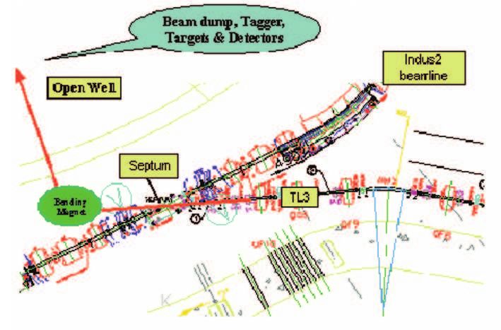
L M Pant

           Figure 1. Photoproduction on a free proton (continuous curve) and bound
           nuclei (data points) [1].

among the quarks lead to the formation of hadrons and eventually the atomic nu-
clei. The cross-section per nucleon for photoabsorption on nuclei shows different
features as shown in figure 1. While the structure assigned to the ∆ excitation of
a bound nucleon is still clearly pronounced, the bump associated with the second
resonance region is washed out [1]. The photoabsorption on a free and on a bound
nucleon are distinctly different, indicating a strong medium effect, a modification
of hadronic properties in nuclear matter.
   Further insight into the generation of hadron masses is expected from studying
modifications of hadron properties by embedding them into strongly interacting
nuclear matter. It is believed that chiral symmetry is partially restored with in-
creasing baryon density and temperature, leading to a low-lying hadronic spectrum.
Experimentally the spectral function of a meson is determined by the sum of the
four-momentum vectors pi of its decay products: m2 = (p1 + p2 )2 . Two conditions
have to be fulfilled to obtain the in-medium spectral function of a meson namely,
   (i) The lifetime of the meson has to be sufficiently short and the recoil velocity
from the production reaction on the nuclear target has to be small enough such
that the meson has a significant probability to decay inside the nucleus.
   (ii) The momenta of the decay products should not be distorted by the final state
interactions within the nuclear medium.
   The present work highlights the ω photoproduction in nuclear medium with the
ELSA facility at Bonn. This apart, we are also looking forward to utilize the elec-
tron beam at the Centre for Advanced Technology (CAT), Indore for experimental
hadron physics in order to step into the intermediate energy nuclear physics regime.
Towards the end, a skeletal outline has been given as regards what we can do in our
country, in immediate future, with the high-energy electron beam now available at
CAT, Indore.

2. Photoproduction of ω at ELSA, Bonn

The cleanest way to investigate the vector meson (ρ, ω, φ) properties in nuclear
matter is provided by exploiting the photoproduction of these mesons from complex

904               Pramana – J. Phys., Vol. 66, No. 5, May 2006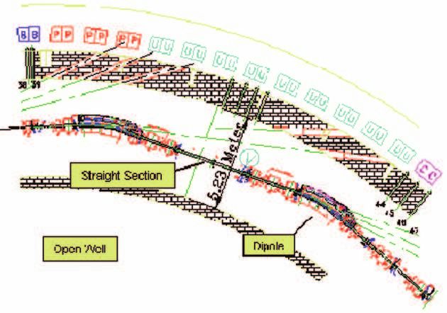
Tagged photon facility at CAT, Indore

           Figure 2. The ELSA facility at Bonn. It consists of the LINAC injector,
           Booster Synchrotron and the Electron Stretcher.

nuclei. As compared to heavy-ion collisions, where temperature and density vary
dramatically with time, the nucleus stays more or less intact in a photonuclear
reaction. Moreover, in contrast to hadron-induced reactions, photoproduction has
the advantage that due to its electromagnetic coupling to the nucleons the reaction
probability of the photon is almost the same for all the nucleons inside the nucleus.
Therefore, all densities of the static density distribution provided by the target
nucleus can be probed. As such, an alternative and complementary way to study
the in-medium modification of the ω meson is to look for the ω → π 0 γ decay mode.
This mode accounts for 8.5% of the total ω decay width, while for ρ it is only 6.8 ×
10−4 (a factor 100 less), which makes it a clean probe to study solely the ω meson
property in matter. The disadvantage of the ω → π 0 γ decay channel is that the
reconstruction of the ω → π 0 γ mode is hampered by the final state interactions of
the π 0 meson in the nucleus, which is expected to be pronounced in case of a large
nuclei. Events in which the emerging π 0 is absorbed in the nucleus are lost. If π 0
rescatters from a nucleon or the nucleus the momentum of the pion is significantly
degraded such that it does not contribute to the invariant mass range near the ω
peak.
   The experiments were performed at the ELSA facility at Bonn from Jan. 2002
to Dec. 2003 using the Crystal Barrel and TAPS detector set-up. ELSA stands for
Electron Stretcher Analag (system). As shown in figure 2, it consists of a 50 Hz
machine with LINAC as an injector to the Booster Synchrotron which increases
the electron energy up to 1.6 GeV. In order to avoid random coincidences in the
experiments, the bunched electron beam is stretched in the Electron Stretcher and
finally a quasi-continuous electron beam is extracted to a maximum of 3.5 GeV for
generating bremsstrahlung photons. This section focuses mainly on the mass of the
photoproduction of ω meson at normal nuclear matter densities. For identifying
the γ + A → ω + X, a coincidence set-up between Crystal Barrel (CB-1290 CsI
crystals) and the Two Arms Photon Spectrometer (TAPS-528 BaF2 crystals) was
set-up at the ELSA facility at Bonn. TAPS was configured as a wall and placed
at forward angles covering polar angles between 5◦ and 30◦ . This set-up allows to

              Pramana – J. Phys., Vol. 66, No. 5, May 2006                       905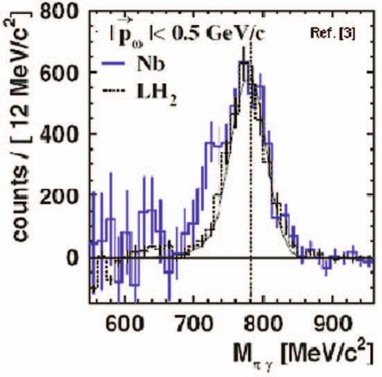
L M Pant

           Table 1. Beam times and statistics for ω photoproduction from various tar-
           gets.

           Target         Target density   Target length    Beam time          ω’s
                             (g/cm3 )          (cm)            (h)

           LH2                0.071             5.0            500         2.25 × 10⁵
           12
              C6              1.67              2.0             85           66,000
           40
              Ca20            1.53              1.0
                                                               100           39,500
           93
                Nb41          8.51              0.1            185           40,000

measure the scattering angle and energy of all the final state photons with a nearly
4π coverage. The π 0 γ invariant mass can be obtained from the measured momenta
of the three final state photons. The CB detector is equipped with an inner detector
consisting of scintillating fibres (SciFi) which allow to discriminate between charged
particles (leptons, protons and charged pions) and neutral particles (photons and
neutrons). It also provides a signal for the first level triggering. Similarly TAPS
spectrometer discriminates between charged and neutral particles via thin plastic
scintillators placed in front of BaF2 crystal. Furthermore, massive particles and
photons/leptons can be separated by pulse-shape and time-of-flight in TAPS [2].
To avoid experimental ambiguities for the interpretation of a possible in-medium
modification of the ω meson the π 0 γ spectra obtained with nuclear targets (C, Ca
and Nb) was compared to the measurement on the free proton (LH2 ). Data were
also taken with deuteron target (LD2 ). Though we do not expect any medium
modification in case of deuteron target, the data is important to understand the ω
production of neutron in a quasi-free kinematics. Table 1 shows the beam times,
ω statistics and other relevant parameters for the ω photoproduction from various
targets. The fraction of ω decaying inside the nucleus were maximized by requiring
the incident photon energy to be close to the production threshold. The photon
energy range was chosen at Eγ = 1.2 GeV with a maximum intensity of 1 × 10⁷ s−1 .
Within this energy range the average cross-section for ω production is estimated to
be σ/A ∼ 5 µb. In figure 3, results obtained for Nb are compared to the reference
measurement on a LH2 target. While for recoiling, long-lived mesons (π 0 , η), which
decay outside the nucleus, a difference in the line shape of the two data samples is
not observed, we find a significant enhancement towards lower masses for ω mesons
produced on the Nb target [3]. For momenta less than 500 MeV/c, an in-medium
ω meson mass of Mmedium = [722 ± 4(stat.) ± 35(syst.)] MeV/c2 has been deduced
at an estimated average nuclear density of 0.6ρ0 .

3. Indus-1 and Indus-2 at CAT, Indore: Proposal for a tagged photon
facility

To understand the physics laws governing the building blocks at low energies, in the
non-perturbative regime, where we encounter them in nature, the complex many-
body system – nucleon, offers the ideal testing ground for concepts of the strong

906                    Pramana – J. Phys., Vol. 66, No. 5, May 2006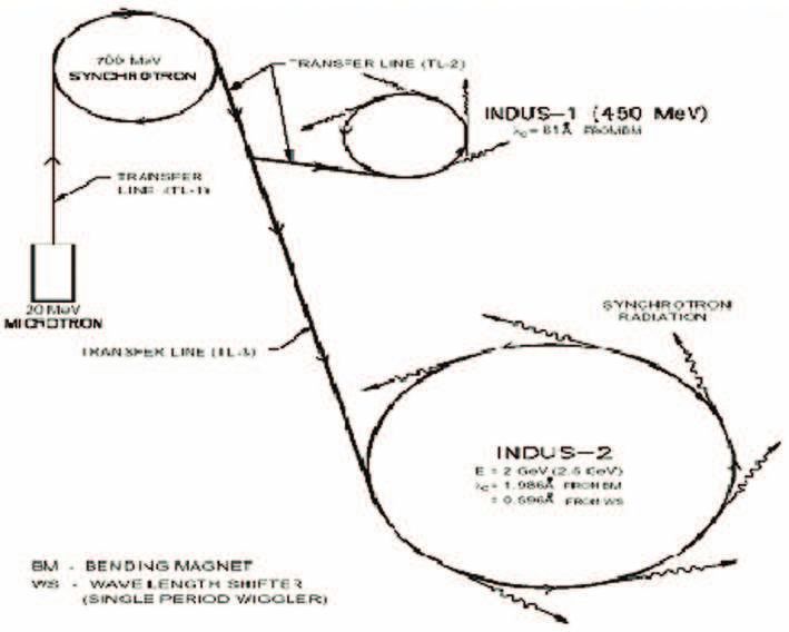
Tagged photon facility at CAT, Indore

           Figure 3. π 0 γ invariant mass for the Nb data (solid histogram) and LH2
           data (dashed histogram) after background subtraction. The error bars show
           statistical uncertainties only. The solid curve represents the simulated line
           shape for the LH2 target [3].

interactions. The dominant decay mode of any excited nucleon state is the emission
of mesons via the strong interactions and photoproduction of mesons is an excellent
tool for the study of nucleon resonances. The high-energy electron beam available
at CAT, Indore can be used for nucleon excitation, thereby studying the decay
properties of the excited states. Indus-1 is a 450 MeV synchrotron radiation source
with a critical wavelength of 61 Å. It was commissioned in June 1999. Indus-2
will be a synchrotron radiation source of nominal electron energy of 2.5 GeV and
a critical wavelength of about 4 Å. Both Indus-1 and Indus-2 are national facilities
accessible to all researchers from national laboratories, academic institutions and
industries in India. With the commissioning of both these facilities, Indian scien-
tists will have powerful sources of photons with wavelengths in the visible, vacuum
ultraviolet, soft X-rays, and hard X-rays. Indus-1 is a 1 Hz machine capable of
providing an external current of about 0.1 nA and has operated successfully with
a current of 200 mA in the storage ring [4].
   Indus-2 is nearing completion and when ready would provide an electron beam
at 2.5 GeV designed for a storage current up to 300 mA. At present, there is no
extraction facility for the electron beam with Indus-2. However, in principle, the
beam can be extracted either from the Booster (700 MeV) or Indus-1. Figures 4
and 5 show the schematic and the actual lay-out of the facilities at Indore. The
repetition cycle of Booster Synchrotron is 1 Hz, i.e. it accepts the beam of 1 µs
width from the Microtron, boosts it and then the extraction process takes place.
The magnets are ramped down again to accept the next pulse from the Microtron.
The single pulse from Microtron (1 µs) is fed as three bunches in the Booster
Synchrotron. The time gap between these bunches is nearly 33 ns. Thus at 1 Hz
repetition rate, the Booster delivers a set of three bunches with a separation of 33
ns between them. The bunch width is almost 10 ns. The ramping time is nearly

              Pramana – J. Phys., Vol. 66, No. 5, May 2006                          907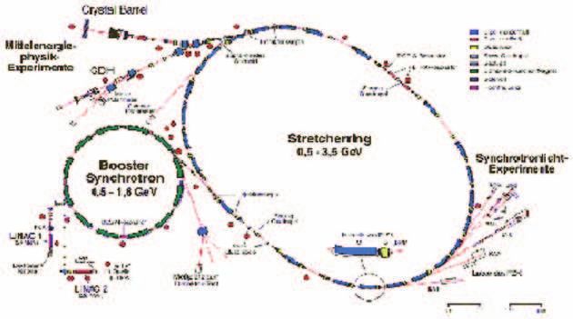
L M Pant
Figure 4. Schematic lay-out of the Microtron, Booster Synchrotron, Indus-1
and Indus-2 facility at CAT, Indore, India
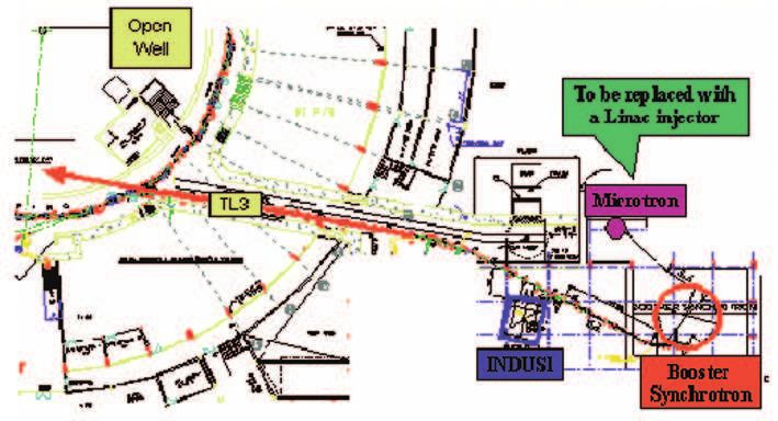
Figure 5. Actual lay-out of the 20 MeV Microtron Injector along with the
Synchrotron Booster (700 MeV), Indus-1 (450 MeV Synchrotron) and part
of the upcoming Indus-2 (2.5 GeV Synchrotron) at CAT, Indore, India. The
transmission line TL3 meets the beam line of Indus-2 at the septum. The
same TL3 can be extended into the ‘open well’ for bremsstrahlung studies.
200 ms, i.e. it accepts the beam at 20 MeV from Microtron and then boosts the
energy up to 450 MeV in nearly 200 ms. The average current in the Booster is 2
mA so that about 1.2 × 10⁹ electrons are distributed in three bunches with nearly
10 ns width of each bunch. The current may be increased by a larger amount (∼3–4
times) with the proposed LINAC (high average current) to replace the Microtron.
908 Pramana – J. Phys., Vol. 66, No. 5, May 2006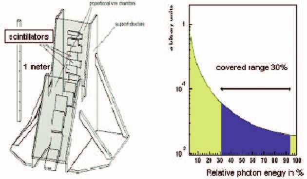
Tagged photon facility at CAT, Indore

           Figure 6. The tagger (left) at ELSA for tagging the electron. The 1/Eγ
           spectrum of the bremsstrahlung photons is shown in the right panel. The
           shaded portion is the range covered with the SAPHIR detector. The tagging
           system was modified for the CB-TAPS system to have an energy range from
           22 to 93% of the electron beam energy.

  There are two different techniques to generate the high-energy photons, namely:
   1. Bremsstrahlung tagging being used at ELSA, MAMI, JLab etc. and
   2. Compton (laser) backscattering being used at BNL, ESRF (GrAAL), Spring8
      etc.
   Bremsstrahlung photons are generated by extracting the electron beam and im-
pinging it on a radiator and thereafter using a magnet to momentum deflect the
electrons and tag their energies in order to know the bremsstrahlung photon en-
ergy. This would need a tagger, preferably based on scintillator fibres coupled to
photomultipliers. The tagger used at Bonn along with the 1/Eγ spectrum of the
bremsstrahlung photons is shown in figure 6. The shaded portion is the range cov-
ered with the SAPHIR detector that was used earlier. The tagging system was
modified for the CB-TAPS system to have an energy range from 22 to 93% of the
electron beam energy. Knowing the energy of the electron beam from its position
on the tagger one can find the energy of the bremsstrahlung photon which is given
as

           Eγ = Ebeam − Etagger .                                                (1)

Depending on the tagger design and its efficiency one can have photons with energy
almost up to 90% of the incident electron energy. Another tagging system being
used at the MAMI (MAinz MIcrotron) facility at Mainz is shown in figure 7. Typical
tagged photon fluxes are listed in table 2. At CAT, Indore, the extracted electron
beam from 700 MeV Booster could provide (Eγmax )brem. ∼ 630 MeV. The 450 MeV,
Indus-1 can similarly provide (Eγmax )brem. ∼ 405 MeV. To start with, one can
extract the beam from either the Booster or Indus-1 and use the tagged photons to
see the behaviour of the large volume BaF2 and other scintillators owned by various
research groups in our country with high energy photons ((Eγmax )brem. ∼ 400–600
MeV).

              Pramana – J. Phys., Vol. 66, No. 5, May 2006                      909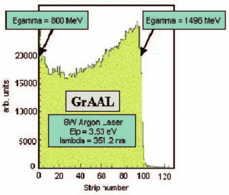
L M Pant

           Table 2. Beam currents at Indore as compared to some of the international
           facilities.

                        Ee
                     (Electron                   γtagged
Facility              energy)    Intensity    (Photon flux)           Features

GrAAL                6.04 GeV     200 mA      1.5 × 10⁶ s−1 Laser backscattered photons,
Grenoble, France                                                  polarized beam,
                                                                  flat distribution
ELSA                 3.50 GeV      20 nA    1.0 × 10⁷ s−1     Bremstrahlung photons,
Bonn, Germany                    (external)                        higher flux,
                                                                 1/Eγ distribution
Indus-1            450 MeV        100 mA           –                     –
CAT, Indore, India
Indus 2              2.5 GeV      300 mA           –                     –
CAT, Indore, India               (designed)

   The high energy beam (2.5 GeV) from Indus-2 is not suitable for bremsstrahlung
studies because of the slow ramping of the dipole magnets. The magnets take
about 5 min to ramp up for 2.5 GeV and after the ring for Indus-2 is filled with
electron bunches, it is to be ramped down to accept the next filling in the ring.
Once the ring is filled with electron bunches and taking into account the ramp-
up and ramp-down times, the duty cycle is close to 1% which is not suitable to
conduct coincidence experiments. However, with the conceptual design for a direct
3 GeV Booster Synchrotron at CAT, the plans can be suitably modified in order
to have a continuous beam operation. To have tagged photon facility generated
through bremsstrahlung mechanism, we would need the following systems as a
skeletal outline:
   1. Availability of electron beam at some coordinates may be after the Booster,
      beyond TL3 into the ‘open well’. This would then need a bending magnet
      (refer to figures 5 and 8).
   2. Another magnet (∼1.5 T) for momentum analyzing the electron beam as it
      hits the radiator for producing bremsstrahlung photons.
   3. Tagger for tagging the electrons based on scintillation fibres (SciFi) and
      PMT’s.
   4. Preferably a 4π detection system consisting of large volume scintillation de-
      tectors (CsI, BaF2 , PbWO4 etc.).
  As shown in figure 8 the electron beam from the Booster Synchrotron at 700
MeV can be taken through the TL3 beam line where it injects the beam into the
Indus-2 beam line. At the septum, the TL3 can be extended forward in the same
direction and then suitably bent with a bending magnet and taken into the ‘open
well’ for generation of tagged bremsstrahlung photons. The electron beam dump
for tagged bremsstrahlung photoproduction studies can be configured inside the

910                Pramana – J. Phys., Vol. 66, No. 5, May 2006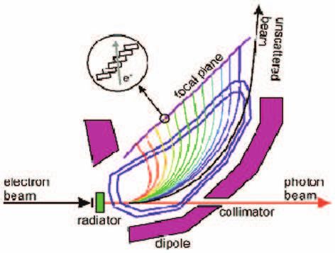
Tagged photon facility at CAT, Indore

           Figure 7. The tagger at the MAMI facility at Mainz.

           Figure 8. The TL3 beam line merging as an injector to Indus-2. The 700
           MeV electron beam from the Synchrotron Booster can be suitably arranged
           to go straight forward and then bend into the open well for producing tagged
           bremsstrahlung photons.

ground of the ‘open well’. The thick walls of the ‘open well’ (thickness ∼75 cm)
would also provide sufficient shielding to contain the associated radiation.
  The other option is to generate a laser backscattered photon. In this technique
one does not have to extract the beam from the storage ring. The experiments
based on synchrotron light can run parallely in a parasitic mode. The high-energy
beam from Indus-2 (2.5 GeV) inside the ring can be utilized to generate laser
backscattered photons. Indus-2 has five straight sections where insertion devices
can be placed and one such straight sections can be utilized for generating the laser

              Pramana – J. Phys., Vol. 66, No. 5, May 2006                         911
L M Pant
Figure 9. A typical spectrum at GrAAL for the laser backscattered photon
[5]. The x-axis shows the strip number of the electron tagger. At GrAAL the
electron energy is 6 GeV which provides backscattered photons with argon
laser (Elp = 3.53 eV, λ = 351.2 nm) in the range from 800 MeV to 1.5 GeV.
backscattered photons. However, the maximum energy of the electron beam (at
2.5 GeV) and the type of laser used (say, argon laser, Elp = 3.53 eV, λ = 351.2
nm) would define the energy spectrum of the photons with Eγmax ∼ 295 MeV. The
energy of the laser backscattered photon is given as
4γ 2 Elp
Eγ = ³ ´, (2)
4γElp
1+ mc2 + δ2 γ 2
where γ = Ee /mc2 , Elp is the energy of the laser photon (∼3 eV) and Eγmax is
the energy of the laser photon scattered at 180◦ for which δ = 0. A typical energy
spectrum for the GrAAL (Grenoble Anneau Accelerateur Laser) facility [5] is shown
in figure 9. The spectrum is in general a flat distribution in contrast to the 1/Eγ
spectrum for the bremsstrahlung photons. The electron energy at GrAAL is 6 GeV
and the spectrum for the laser backscattered photon from an argon laser (Elp ∼ 3.53
eV) is limited between 800 MeV to 1.5 GeV. The laser has to be accordingly tuned
to cover different ranges of photon energies (Elp ∼ 2.41 eV provides a range for
Eγ from 600 MeV to 1.1 GeV). The photon fluxes are however a factor 10 less
than those generated with bremsstrahlung techniques. The tagging detector, in
case of laser backscattering, is one of the most delicate part of the experiment.
The device has to be extremely compact (silicon microstrips), reside in the vacuum
chamber of the storage ring, as close as possible to the main electron orbit, and
must work in the environment of the storage ring, where high fluxes of X-rays are
produced. At CAT, Indore, one of the straight sections in the Indus-2 beam line can
be augmented for installation of the laser backscattered photon facility. The dipole
subsequent to the straight section would bend the electrons undergoing interaction
912 Pramana – J. Phys., Vol. 66, No. 5, May 2006Tagged photon facility at CAT, Indore
Figure 10. One of the straight sections in the Indus-2 beam line could be
augmented for installation of the Laser Backscattered Photon facility. The
dipole subsequent to the straight section would bend the electrons undergoing
interaction with the laser photon for the purpose of tagging.
with the laser photon for the purpose of tagging. As shown in figure 10 one of
the straight sections in the Indus-2 beam line could be utilized for injecting the
laser photon and subsequently the backscattered photon would pass through the
existing ports on the walls to the user’s area. The dipole immediately after the
straight section would deflect the scattered electrons and a tagger would have to be
designed in the vicinity of the dipole to tag the scattered electrons. Alternatively
the angle at which the laser backscattered photon emerges through precision slits,
placed in the straight section can also tell us about the range of photon energies
– of course with a coarser resolution. One of the most interesting features of the
laser backscattered photon beam is its polarization that is obtained very easily: the
laser produces completely polarized photons whose polarization is kept during the
backscattering process. The backward Compton scattering of laser light against
high energy electrons circulating in a storage ring, produces an almost flat energy
spectrum with high polarisation, but this technique is really challenging. The laser
beam position also needs to be controlled and stabilized with an angular accuracy
of ∼2 × 10⁻⁶ radian. Table 2 shows a comparison of the beam currents at CAT,
Indore as compared to some of the international facilities.
To augment a laser backscattered photon facility, we would need the following
systems as a skeletal outline:
1. A laser system (say, 8 W argon laser, Elp = 3.53 eV, λ = 351.2 nm or a
similar system).
2. Availability of one of the straight sections in the Indus-2 beam line.
3. A compact tagger (preferably Si µ strips) for tagging the electrons bent by
the dipole immediately after the straight section.
4. A 4π detection system similar to the one discussed in case of bremsstrahlung.
Pramana – J. Phys., Vol. 66, No. 5, May 2006 913L M Pant
With the existing photon energies generated either by bremsstrahlung or laser
backscattering, one cannot immediately investigate into the frontiers in the inter-
mediate energy nuclear physics. Nevertheless, it could be an excellent starting point
for venturing into the new domain of intermediate energy nuclear physics through
photoproduction in our country. With trained manpower dealing with the super-
conducting magnets at LHC (CERN), one can visualize and enhance the electron
beam energy at CAT, Indore in the range of 6 to 8 GeV using superconducting
dipoles. With the existing infrastructure at least the experimental pion physics
can be initiated in our country. The large-sized (∼25–30 cm in length) BaF2 crys-
tals can be calibrated with the electron/photon beam itself. Photon-induced data
will be a very important database in future since any projects for the accelerator-
driven sub-critical systems (ADSS) will be required to have precise information
of (γ, n) reactions. In future, study of nuclear structure by means of nuclear res-
onance fluorescence, astrophysics with photoreactions, basic symmetry studies of
the parity-violating force in the nuclear medium will be possible with linear and
circularly polarized low-energy γ-ray beam (∼ few MeV photons).
Acknowledgements
I am indebted to Prof. Volker Metag, David Trnka, and others working for the
CBELSA-TAPS Collaboration at Bonn, Dr S Kailas for his continuous encour-
agement, guidance and support and Dr Gurnam Singh and Amlendu Sharma for
explaining to us the details of the facilities at CAT, Indore, India. I am also thank-
ful to Prof. M Fujiwara with whom I had scintillating discussions on the above
subject during the Workshop on Hadron Physics at Puri.
References
[1] C Amsler et al, Nucl. Phys. A622, 315c (1997)
[2] A Martin et al, Nucl. Instrum. Methods A417, 137 (1998)
[3] D Trnka, L M Pant and the CBELSA-TAPS Collaboration, Phys. Rev. Lett. 94, 192303
(2005)
[4] R V Nandedkar et al, Curr. Sci. (2002) 82
[5] C Schaerf, Nuclear Physics News 2(1), 7 (1992)
914 Pramana – J. Phys., Vol. 66, No. 5, May 2006You can also read