MULTI-SENSOR BLUETOOTH INTERFACE - NexusGEO - Geosense
←
→
Page content transcription
If your browser does not render page correctly, please read the page content below
V1.1 May 2021

                       MULTI-SENSOR
                BLUETOOTH INTERFACE
                             NexusGEO

    I
    N
    S
    T
    R
    U
    C
    T
    I
    O
    N

    M
    A
    N
    U
    A
    L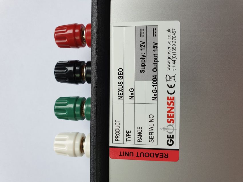
V1.1 May 2021

                ITEM                                PAGE

                CONTENTS                            2
  1.0           INTRODUCTION                        3
  1.1           General description                 3
  1.2           Theory of operation                 4
  1.3           Software                            4
  1.4           Host system requirements            4
  1.5           Electromagnetic compatibility       4
  1.6           Theory of operation                 5

  2.0           CONFORMITY                          6
  3.0           MARKINGS                            7

  4.0           PACKAGING/HANDLING                  7
  4.1           Inspection & storage                8
  5.0           GETTING STARTED                     8
  5.1           Batteries                           8
  5.2           Installing mobile app               8
  5.3           Permissions                         8
  6.0           OPERATION                           9
  6.1           Connecting sensors                  10
  6.2           Using the app                       11
  6.2.1         Home and Bluetooth connection       11
  6.2.2         Taking readings                     13
  6.2.3         Adding sensors                      14
  6.2.4         Selecting sensor                    16
  6.2.5         Site zero readings                  17
  6.2.6         Save readings                       18
  6.2.7         Edit sensor                         19
  6.2.8         Delete sensor                       19
  6.3           Data                                20
  6.3.1         FTP data                            20
  6.3.2         Email / save to file                21
  6.3.3         Delete                              21
  6.3.4         Settings                            21
  6.3.5         Exported csv files                  21
  7.0           MAINTAINANCE                        22

  8.0           TROUBLESHOOTING                     22
  9.0           SPARE PARTS                         22

  10.0          SPECIFICATIONS                      23
  11.0          RETURN OF GOODS                     24
  12.0          LIMITED WARRANTY                    25

                                                2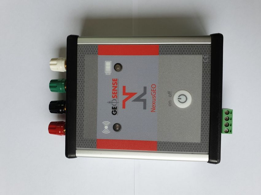
V1.1 May 2021

1.0 INTRODUCTION

This manual is intended for all users of the Geosense® NexusGEO readout unit and
provides a guide for its operation and maintenance.

                    It is VITAL that personnel responsible for the use of
                   the NexusGEO READ and UNDERSTAND the manual,
                             prior to working with the equipment.

1.1 General Description

The NexusGEO is a portable multi-sensor battery-powered Bluetooth interface, designed to
be used with any Android device with Bluetooth and android OS 8 or later* for wireless
gathering and storage of sensor readings.

It is provided with a battery charger and four individually coloured leads to connect to
analogue sensors and a terminal block for digital sensors.

The NexusGEO is to be used with a mobile application (app) which has an easy to use
interface and manages data acquisition from the following single sensor outputs:

•       Vibrating wire (VW)
•       4-20mA
•       Volt
•       mV/V
•       Pt100
•       NTC
•       Geosense Digital RS485

                   Analogue connections can be made directly to the terminals, using the
                    fly leads with crocodile clips supplied with the unit or with the green
                              terminal block on the bottom of the unit for RS-485

*Please note that due to ever changing android device specifications, these specifications are subject to change

                                                                    3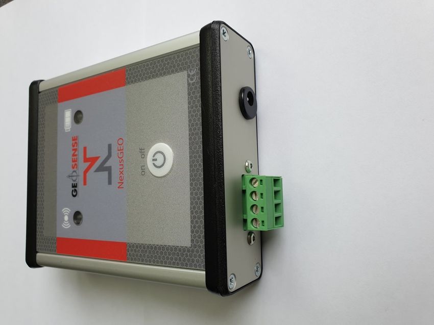
V1.1 May 2021

1.2 Theory of Operation

The NexusGEO is a Bluetooth interface between a range of sensors and an Android
device. The raw signal output from the sensor is transferred from the NexusGEO to the
Android device via the NexusGEO app and the values displayed on the Android device
where they can be converted into Engineering units, stored on the device and transferred
via FTP or email.

1.3 Software

The NexusGEO mobile application (app) allows the user to configure the device with a wide
range of sensor types and download the data. It is available as a free download on the
Google Play Store.

As part of continual improvement, updates to the software may occur and should be
downloaded to ensure the current version is being used. Please visit the Google Play Store
to check for the latest version.

1.4 Host System Requirements

•     Android device with Android OS Version 8 or higher (Minimum SDK Version 19) and
      Bluetooth
•     In order to use FTP functionality, a FTP server will be required.

1.5 EMC – Electro Magnetic Compatibility

EMC is the electromagnetic interaction of electrical and electronic equipment with other
electrical and electronic equipment. All electronic devices have the potential to emit and be
affected by electromagnetic fields. With the reduction in size of electrical components and
the ever increasing amount of electrical & electronic devices such as mobile phones, two-
way radios, safety control systems, signalling, generators, welding equipment, power cables
etc in all environments, especially construction sites, there is a huge potential for devices to
interfere with each other.

The NexusGEO has been designed and tested for EMC under the relevant CE marking
directives to ensure compliance and reliable operation

                                               4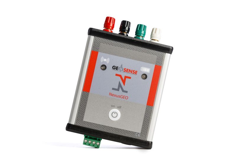
V1.1 May 2021

1.6 Philosophy of Operation

Calibration Factors

The NexusGEO is designed to work with a wide-range of sensors. Most sensors will require
calibration factors to convert from the raw reading into an engineering unit. All Geosense
sensors are dispatched with a calibration sheet with any factors that may be needed. Digital
sensors have the calibration information embedded in the sensor. The NexusGEO app will
allow you to enter this information when you add the sensor.

Wireless Connection and Data Reading

The NexusGEO uses wireless Bluetooth technology to communicate between the Android
device and the app. Once paired on the phone, connection can be established at the push
of a button, and begin taking readings moments later. Live readings are saved temporarily
in a buffer that clears when readings are stopped being taken.

Linear and Polynomial Calculations

Most sensors make use of calibration factors and raw readings to convert to engineering
units using either Linear or Polynomial calculations. The equations are detailed on the
calibration sheets.

Site Zero Readings

Sensors that convert to engineering units using Linear or Polynomial calculations can use a
site zero reading and apply this to the result to make it relative. If you choose to not apply a
site zero reading, the result will be absolute (site zero defaults to zero).

Saving Readings

As readings accumulate in the buffer, you can choose to save the readings into a database.
Sensor information, raw readings and engineering conversions are all saved for reference
later.

Using the Data

Saved data in the app database can then be saved to csv and sent via an FTP, Email or
saved to the local phone device for future use

                                                5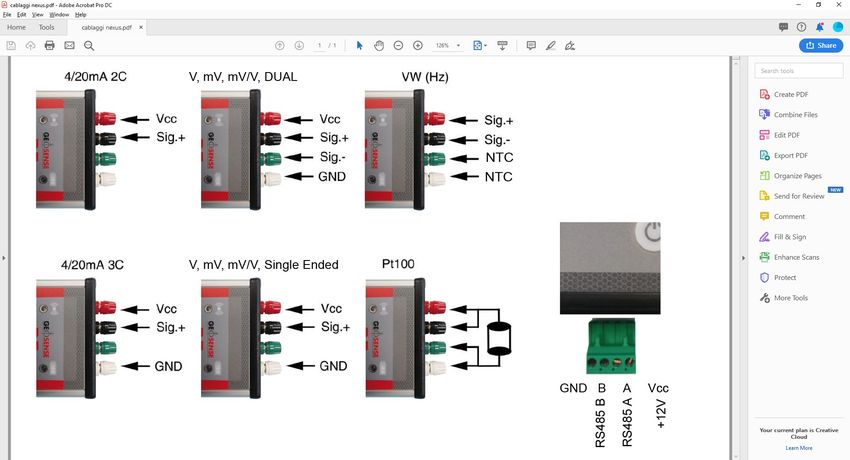
V1.1 May 2021

2.0 CONFORMITY

    Geosense Ltd
    Nova House
    Rougham Industrial Estate
    Rougham, Bury St Edmunds
    Suffolk , IP30 9ND
    United Kingdom

    Tel: +44 (0)1359 270457
    www.geosense.co.uk

          EC Declaration of Conformity
We Geosense Ltd at above address declare that the equipment detailed below, complies
with the requirements of the following EU Directives:-

•       Low Voltage Directive 2014/35/EU
•       Electromagnetic Compatibility Directive 2014/30/EU
•       Waste electrical and electronic equipment (WEEE) 2012/19/EU
•       Restriction on the use of certain Hazardous Substances (RoHS2) 2011/65/EU

Equipment description:           NexusGEO
Make/Brand:                      Geosense
Model Numbers:                   NxG

Compliance has been assessed with reference to the following harmonised standard:
EN 61326-1:2006 Electrical equipment for measurement, control and laboratory use.
EMC requirements. General requirements.

A technical file for this equipment is retained at the above address.

Martin Clegg
Director
Rougham, June 2019

                                              6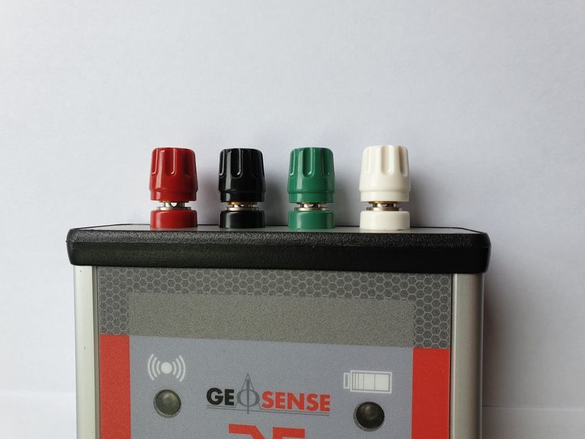
V1.1 May 2021
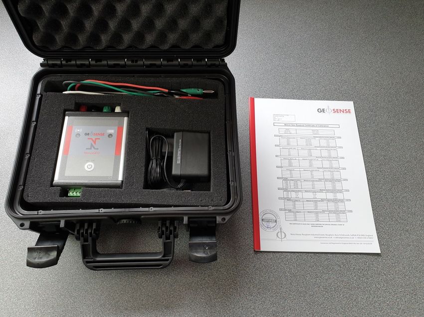
3.0 MARKINGS
A GeosenseTM NexusGEO is labelled with the following information:-
Manufacturers telephone number & website address
Product group: NexusGEO
Product type: NxG
Input supply: 12V DC
Serial number: NxG-XXXX
CE mark
WEEE mark
4.0 PACKAGING/HANDLING
The NexusGEO comes in a robust carry case and packed for transportation to site.
Packaging is suitably robust to allow normal handling by transportation companies.
Inappropriate handling techniques may cause damage to the packaging and the enclosed
equipment. The packaging should be carefully inspected upon delivery and any damage
MUST be reported to both the transportation company and Geosense.
The NexusGEO is a precision measuring instrument and its associated equipment should
always be handled with care during transportation, storage and use.
Once the shipment has been inspected, it is recommended that the GeosenseTM
NexusGEO components always remains in the carry case for storage or transportation.
7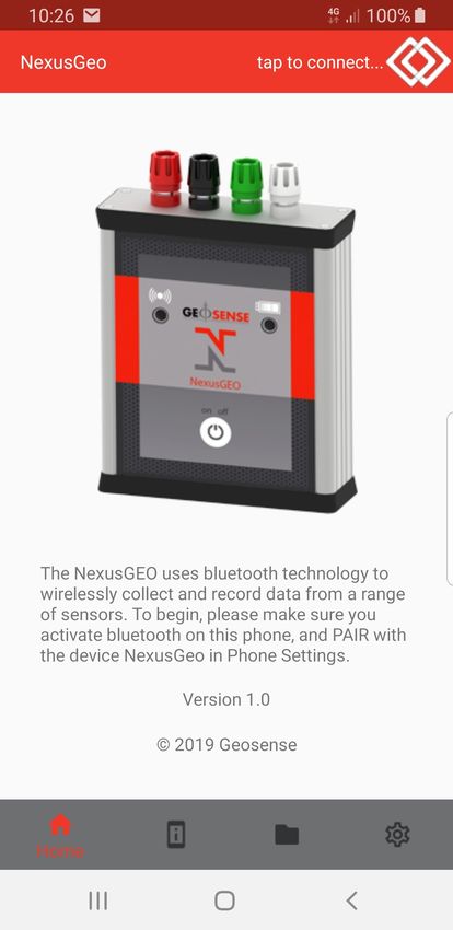
V1.1 May 2021

4.1 INSPECTION/STORAGE

It is important to check all the equipment in the shipment as soon as possible after taking
delivery and well before installation is to be carried out. Check that all the components
detailed on the documents are included in the shipment. Check that the equipment has not
been physically damaged.

The NexusGEO contains electronics and batteries and whilst they are designed for outside
use and mounted within a waterproof (IP66) enclosure the internal circuit board can be
affected by excessive moisture, dust and temperature. When not in use they should be
stored in a cool, dry location.

5.0 GETTING STARTED

This section of the manual is intended for all users of the NexusGEO and is intended to
provide guidance with respect to its use in obtaining data from a sensor.

5.1 BATTERIES

The NexusGEO has internal re-chargeable batteries which are not replaceable in the field.
If there is a problem with the batteries and change is required please return the unit to
Geosense.

5.2 INSTALLING MOBILE APP

In order to work with an Android device the NexusGEO Mobile app will need to be
downloaded from the Google Play store.

5.3 PERMISSIONS

To enable full functionality of the app, access permissions will be required. To enable
permissions on your phone go to Settings -> Apps -> NexusGEO -> Permissions ->
Storage and                             toggle this on.

                                              8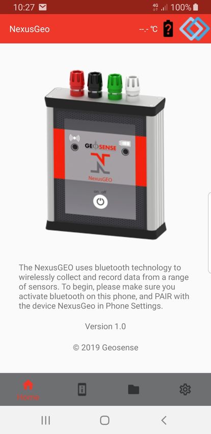
V1.1 May 2021

6.0 OPERATION

The unit compromises of:

1.    Red, Black, Green and White terminal sockets for analogue connections

2.    Bluetooth connection indicator

•     Blue– Connected and taking readings
•     Red– Disconnected
•     Clear– No Bluetooth connection

3.    Battery level indicator

•     Green– Full battery level
•     Amber– Half battery level
•     Red– Low battery, charge immediately

4.    On/Off power button

•     On– Hold for 1 second to power unit on
•     Off– Hold for 4 seconds to power off the device

5.    RS485 digital connector

                                 1

                                       2                3

                                                    4

                                        5               6

                                              9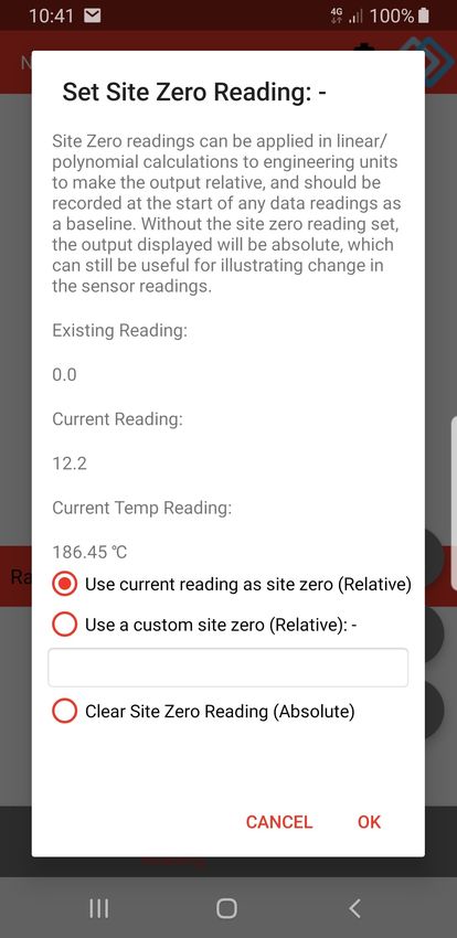
V1.1 May 2021

6.1 CONNECTING SENSORS

The NexusGEO can be wired in the follow ways using the terminals or crocodile clips
provided to read analogue sensors. Ensure that each wire is fully secured before any
readings are taken.

It can also be wired to read a Geosense RS-485 digital sensor using the green connector
block on the bottom of the unit. Ensure that each wire is fully secured using the screw
terminals to establish connection.

NOTE: For other RS-485 sensors please contact Geosense®

                                            10
V1.1 May 2021
6.2 USING THE APPLICATION
6.2.1 HOME AND BLUETOOTH CONNECTION
Turn on the NexusGEO device by holding the power switch for 1 second. The device will
make a long audible beep and the battery light will display the current battery level for short
period of time before going clear. The power button can be pressed again to show the
battery level when required.
The battery indicator will periodically flash to indicate the device is switched on, and show
current battery levels.
The NexusGEO should be able to communicate with the app wirelessly via Bluetooth with a
range up to around 4 metres. On the android device turn on Bluetooth and pair with device
‘NexusGEO’. No pairing code is required.
Open the mobile APP on the android device and the following screen should be shown: -
11V1.1 May 2021
6.2.1 HOME AND BLUETOOTH CONNECTION CONT.
Menu Icons:
• Home
• Readings– Configure sensor and begin to take readings
• Data– Access any readings that have been saved and download them
• Settings
With the android device in range, tap the Bluetooth icon in the top right of the screen to
connect to the device. The icon will change to blue as shown below.
The Bluetooth indicator on the NexusGEO will remain clear until
readings being taken via the APP
The temperature and battery indicators in the APP will only update
when readings start being taken from the sensor
To disconnect from the device, press the Bluetooth icon again.
To turn off the NexusGEO, hold the power button down for 4 seconds. The device will make
short audible beep before all lights will turn off.
12V1.1 May 2021
6.2.2 TAKING READINGS
Pressing the Reading menu will show the following screen: -
Reading Menu Items:
• Add Sensor
• Select Sensor
• Edit Sensor
• Delete Sensor
Before readings are taken sensor information must be added, this includes sensor type and
calibration factors
13V1.1 May 2021
6.2.3 ADD SENSOR
Press ‘Add Sensor’ and the screen will change to:
The NexusGEO supports a wide range of sensors types, and each one has different
calibration factors that can be configured to convert to engineering units. Please refer to the
following table to the select the appropriate sensor type.
Sensor Type Calibration Factors Reading Units Engineering Units
4-20mA 3 Wire Sensor None mA None
Linear (K)
4-20mA Crack Meter mA Mm
Polynomial (A, B)
Linear (K)
4-20mA Piezometer mA kPa, Bar, PSI, mH20
Polynomial (A, B)
Linear (K)
4-20mA Transducer mA kPa, Bar, PSI, mH20
Polynomial (A, B)
Inclinometer Linear (M, C)
mA Sin(X), Degrees, mm/M, Radians
(Analogue) Polynomial (A, B, C, D)
Inclinometer (Digital) None Sin(X) Degrees, mm/M, Radians
14V1.1 May 2021
6.2.3 ADD SENSOR CONT.
Sensor Type Calibration Factors Reading Units Engineering Units
mV/V Displacement
None mV/V None
Meter
mV/V Strain Gauge
Linear (K) mV/V kN
Load Cell
NTC Temperature
None Ohms °C
Sensor
PTC Temperature
None Ohms °C
Sensor
Linear (M, C)
Sin(X), Degrees, mm/M, Radi-
Tiltbeam (Analogue) Polynomial (A, B, C, mA
ans
D)
None as they are on
Tiltbeam (Digital) Sin(X) Degrees, mm/M, Radians
the chip
Linear (M, C)
Sin(X), Degrees, mm/M, Radi-
Tiltmeter (Analogue) Polynomial (A, B, C, mA
ans
D)
None as they are on
Tiltmeter (Digital) Sin(X) Degrees, mm/M, Radians
the chip
Voltage Output Tiltme-
None V None
ter
Voltage Single None V None
Vibrating Wire Crack Linear (K)
Digit (B) mm
Meter Polynomial (A, B)
Vibrating Wire Dis- Linear (K)
Digit (B) mm
placement Meter Polynomial (A, B)
Vibrating Wire Em-
bedment Strain Batch Factor
Digit (B) Microstrain
Gauge (50mm, Gauge Factor
150mm, 250mm)
Vibrating Wire Hy- Linear (K)
Digit (B) kN
draulic Load Cell Polynomial (A, B)
Linear (K)
Vibrating Wire Liquid
Thermal (T) Digit (B) kPa, Bar, PSI, mH20
Level Settlement
Polynomial (A, B)
Vibrating Wire Load
None Digit (B) None
Cell
Linear (K)
Vibrating Wire Pie-
Thermal (T) Digit (B) kPa, Bar, PSI, mH20
zometer
Polynomial (A, B)
Linear (K)
Vibrating Wire Pres-
Thermal (T) Digit (B) kPa, Bar, PSI, mH20
sure Cell / NATM
Polynomial (A, B)
Linear (K)
Vibrating Wire Sister
Polynomial (A, B) Digit (B) kN, Microstrain
Bar / Rebar
Strain (S)
Vibrating Wire Soil Linear (K)
Digit (B) mm
Extensometer Polynomial (A, B)
Vibrating Wire Spot Batch Factor
Digit (B) Microstrain
Weld Strain Gauge Gauge Factor
Vibrating Wire Surface
Batch Factor
Mount Strain Gauge Digit (B) Microstrain
Gauge Factor
(89mm, 150mm)
Vibrating Wire Tem- Linear (K)
Digit (B) °C
perature Transducer Polynomial (A, B)
Linear (K)
Vibrating Wire Trans-
Thermal (T) Digit (B) kPa, Bar, PSI, mH20
ducer
Polynomial (A, B)
Vibrating Wire Weir
None Digit (B) None
Monitor
15V1.1 May 2021
6.2.3 ADD SENSOR CONT.
With the appropriate sensor type selected, fill in the relevant factors and choose engineering
units (if required). Then press ‘Add Sensor’. A validation check will be made to make sure
sensor has a reference name and valid calibration factors.
When adding sensors, some sensor types will add more than one
sensor into the app. This is because analogue connections can only
read from one sensor at a time, and so for instance with a biaxial
tiltmeter, a sensor will be added for each axis (A and B).
When a sensor is added, the app will automatically go to the select sensor screen.
6.2.4 SELECT SENSOR
At the top of the select sensor screen there is a searchable select box displaying a list of
sensors currently configured on the aap. Select the sensor currently connected to the
NexusGEO and hold down the ‘Hold To Take Reading’ button for 1 second.
Note: Holding down the ‘Hold To Take Reading’ will give the user haptic feedback. This can
be turned off in the app settings.
The screen will change to show:
16V1.1 May 2021
6.2.4 SELECT SENSOR CONT.
Whilst taking a reading it is not possible to change the selected sensor,
or delete the selected sensor. To do this, stop taking readings.
This screen may differ slightly based on sensor type selected. The controls are: -
• Readings – live readings will update on screen approximately every second. Up to 3
readings can be shown on screen at the same time for the same sensor (Digital
tiltmeter shows A-Axis, B-Axis and Temperature).
• Raw Units / Engineering Units Selector – Will switch onscreen readings based on
information added during the sensor setup. Any calibration factors and engineering
units can be edited live whilst readings are being taken by pressing the edit sensor
button.
• Set Site Zero
• Save Readings
• Stop Taking Readings
As the app shows the live readings, they are stored in a temporary internal buffer, these can
be saved so that readings are not missed
6.2.5 SITE ZERO READINGS
17V1.1 May 2021
6.2.5 SITE ZERO READINGS CONT.
When converting raw readings into engineering units, a site zero reading can be set to make
the calculation relative, rather than absolute. This button enables the user to set, customise
and clear the site zero value. Any site zero value that is set, will be saved to the sensor and
automatically applied whenever the sensor is being read again (unless removed). The site
zero reading is being applied when the button changes colour to green:
6.2.6 SAVING READINGS
Readings can be stored from the temporary internal buffer using save button shown above
A default option for this selection can be saved in the settings screen,
which disables this screen from being shown when saving.
18V1.1 May 2021
6.2.7 EDIT SENSOR
After a sensor has been added, the edit sensor button
can be used to make changes to the sensor. Certain
information cannot be changed such as reference name
and serial number.
6.2.8 DELETE SENSOR
Select the sensor to be deleted and press the delete
button. The user will be asked to confirm this action.
19V1.1 May 2021
6.3 DATA
Any data that has been saved by the user when reading sensors is shown in this list (Most
recent data at the top). Controls are: -
• Select All / Deselect All
• FTP Upload
• Email / Save to File
• Delete
6.3.1 FTP DATA
FTP Settings need to be entered into the settings screen and the FTP
Connection Tested before taking advantage of this feature. Data
storage permission is also required to generate the temporary csv file
that will be uploaded.
Select which data sets are to be uploaded via FTP. Press the FTP button at the bottom left
of the screen. CSV files of the data are generated automatically with all readings and
information about the sensor.
An on-screen notification will alert the user when the upload has successfully completed.
CSV files are saved using the file name prefix ‘Export’ followed by a number. Be aware that
if a file already exists on the FTP server at this location, with this filename, it will be
overwritten.
20V1.1 May 2021
6.3.2 EMAIL / SAVE TO FILE
Email and Save to file requires data storage permissions to generate
the csv file that will be sent.
Select which data are to be saved to file or send via email. Then press the ‘Email / Save to
File’ button at the bottom middle of the screen. CSV files of the data are generated on the fly
with all readings and information about the sensor. The phone operating system will ask
what the user would like to do, i.e. Save or Email.
For ‘Save to File’, navigate on your android device to your files and look for a csv file starting
‘Export’. For Email, an email will be auto-generated with the datasets attached as csv’s. The
user can then enter the email address you want to send the files to.
Default email addresses can be set in the settings screen
6.3.3 DELETE
Select which data sets to be deleted from the app. Then press the delete button. The user
asked to confirm permanent deletion before the delete occurs.
6.3.4 SETTINGS
The settings screen enables the user to customise: -
• Haptic feedback when taking a sensor reading
• Default save options
• FTP connection details
• Default email address
6.3.5 EXPORTED CSV FILES
Exported CSV Files are comma separated CSV files with UTF8 encoding. Excel can be
used to import the csv file as shown: -
21V1.1 May 2021
7.0 MAINTENANCE
The maintenance for the NexusGEO is minimal for most applications but it should be kept
as clean and dry as possible.
However users should be aware that the unit contains a rechargeable NiCad battery.
Therefore, if not used for long periods of time, the batteries may discharge.
8.0 TROUBLESHOOTING
The NexusGEO app contains a large amount of self help and therefore the user should
follow any help found within the app itself.
For any Bluetooth communication problems, please ensure the device and app are within
range (and fully charged) and try connecting again.
Please contact Geosense for any further assistance.
9.0 SPARE PARTS
The following spares are available for the NexusGEO:
Item Part Number
MP12/VWR1 Charger with 4 plug set Q22-151
VWR1 Crocodile Connector Cable Set G200-114
22V1.1 May 2021
10.0 SPECIFICATIONS
ITEM SPECIFICATION
Signal Inputs VW (Hz), mA, V, mV/V, Pt100, NTC, VW, RS-485
Range VW Hz 400-5000
mA 4-20
V Single ended 0-100
V Differential 0-10
mV/V Singled ended 0-20
mV/V Differential 0-1000
Pt100 Ω 15-400
NTC Ω 250-50,000
Power Supply Internal 12Vdc Ni-Mh battery, rechargeable
Sensor supply +20V, +12V, +5V, 750uA, 50uA
Current supply @12V 100mA @ 4-20mA, no load
85mA @ +20V single, no load
70mA @ +12V dual, no load
60mA @ mV/V dual, no load
72mA @ Pt100, 100 Ω load
55mA @ NTC, 3K Ω load
60mA @ VW, 777.1Hz
15mA @ no Bluetooth connection
Measurement resolution 24 bit, 0.1Hz for VW
Display Android device & NexusGEO app
Sensor connection Analogue (4mm socket), Digital RS-485
Temperature stability +15ppm/ºC maximum
Operating Temperature -20 to +70°C
IP Rating IP65
Dimensions L x B x H 150 x 105 x 35mm
Weight 465g
23V1.1 May 2021
11.0 RETURN OF GOODS
11.1 Returns procedure
If goods are to be returned for either service/repair or warranty, the customer should contact
Geosense® for a Returns Authorisation Number, request a Returned Equipment Report
Form QF034 and, prior to shipment. Numbers must be clearly marked on the outside of the
shipment.
Complete the Returned Equipment Report Form QF034, including as much detail as
possible, and enclose it with the returned goods and a copy of the form should be faxed or
emailed in advance to the factory.
11.2 Chargeable Service or Repairs ( Inspection & Estimate )
It is the policy of Geosense® that an estimate is provided to the customer prior to any repair
being carried out. A set charge for inspecting the equipment and providing an estimate is
also chargeable.
11.3 Warranty Claim ( See Limited Warranty Conditions )
This covers defects which arise as a result of a failure in design or manufacturing. It is a
condition of the warranty that the GeosenseTM NexusGEO must be installed and used in
accordance with the manufacturer’s instructions and has not been subject to misuse.
In order to make a warranty claim, contact Geosense® and request a Returned Equipment
Report Form QF034. Tick the warranty claim box and return the form with the goods as
above. You will then be contacted and informed whether your warranty claim is valid.
11.4 Packaging and Carriage
All used goods shipped to the factory must be sealed inside a clean plastic bag and packed
in a suitable carton. If the original packaging is not available, Geosense® should be
contacted for advice. Geosense® will not be responsible for damage resulting from
inadequate returns packaging or contamination under any circumstances.
11.5 Transport & Storage
All goods should be adequately packaged to prevent damage in transit or intermediate
storage.
24V1.1 May 2021
12.0 LIMITED WARRANTY
The manufacturer, Geosense Ltd, warrants the Geosense® NexusGEO
manufactured by it, under normal use and service, to be free from defects in
material and workmanship under the following terms and conditions:-
Sufficient information has been provided to Geosense by the purchaser as regards
the nature of its use to allow Geosense to confirm the applicability of the
NexusGEO.
The NexusGEO shall be used in accordance with the manufacturer’s
recommendations.
The equipment is warranted for 1 year from the date of shipment from the
manufacturer to the purchaser.
The warranty is limited to replacement of part or parts which, are determined to be
defective upon inspection at the factory. Shipment of defective part or parts to the
factory shall be at the expense of the Purchaser. Return shipment of repaired/
replaced part or parts covered by this warranty shall be at the expense of the
Manufacturer.
Unauthorised alteration and/or repair by anyone which, causes failure of the unit or
associated components will void this LIMITED WARRANTY in its entirety.
The Purchaser warrants through the purchase of the NexusGEO multi sensor
interface that he is familiar with the equipment and its proper use. In no event
shall the manufacturer be liable for any injury, loss or damage, direct or
consequential, special, incidental, indirect or punitive, arising out of the use of
or inability to use the equipment sold to the Purchaser by the Manufacturer.
The Purchaser assumes all risks and liability whatsoever in connection with the
NexusGEO equipment from the time of delivery to Purchaser.
25V1.1 May 2021
26You can also read