Muons for cooling demonstrator - ISIS C. T. Rogers Rutherford Appleton Laboratory - CERN Indico
←
→
Page content transcription
If your browser does not render page correctly, please read the page content below
Muons for cooling demonstrator

                 C. T. Rogers
                      ISIS
        Rutherford Appleton Laboratory
Questions
What do we want to test?
What is the requirement on beam?
What is the plan looking forwards?
2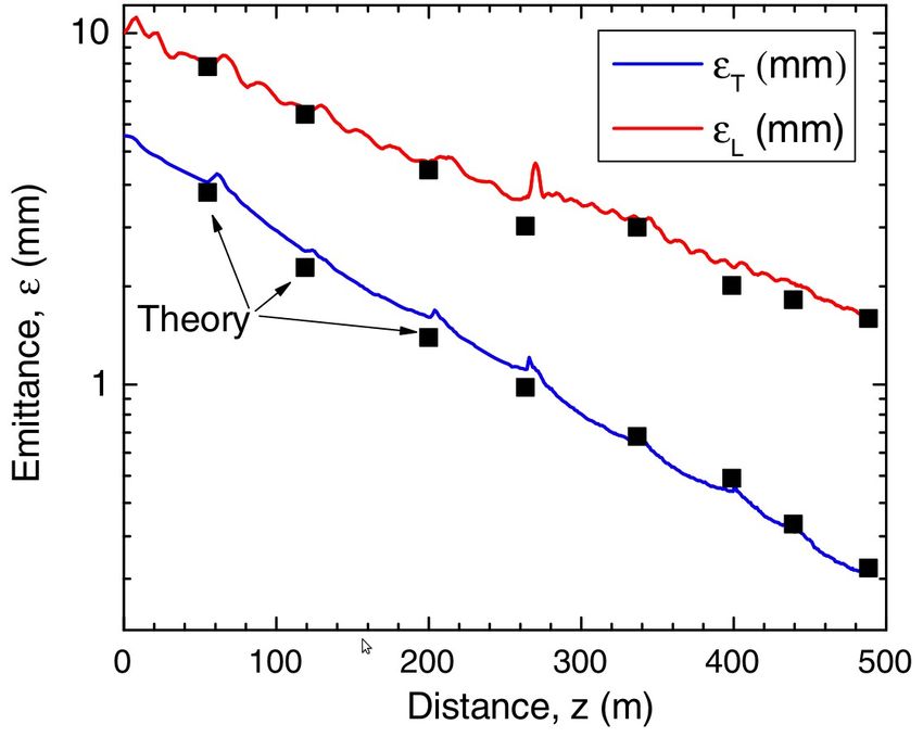
Future Experiment

                      “MICE-like”

Final
coolin
g

                                    Rectilinear B (Stage
                                    B8)

                    MICE

                                                           3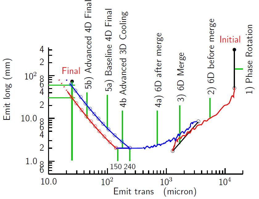
What should the facility demonstrate?

                Performance does not match simulation, for example because                                                                                                     Further experimental measurements of energy
                energy straggling is underestimated, alignments can’t be achieved,                                         Literature review on straggling; simulation study straggling may be necessary. Integration test of
Rectilinear B   etc                                                                  3 Reduced performance               2 of impact on uncertainty in straggling distribution cooling apparatus.
                                                                                                                                                                              Proof of breakdown suppression with a
                                                                                                                                                                              “production” cavity and a reasonable production
                RF voltage cannot be achieved, for example because gradients are                                                                                              run of several cavities, including realistic
                found to be above break down limit                                   3 Back off on RF requirements       2                                                    magnetic fields
                                                                                                                           Design of magnets is required including e.g.       Prototyping of magnets. Demonstration of QPS
                Magnetic field strength cannot be achieved                           3 Back off on magnet requirements   3 force calculations, support design                 system in a reasonable magnet line.
                Radiation load on the magnets is too high due to regular beam          Back off on magnet requirements
                losses and muon decay                                                2 and add extra shielding           1
                Heat load on the absorber is challenging to manage                   1 Split the beam?                   3 Further simulation and design work
                Beam loading of RF cavities
                Space charge

                                                                                                                           Further optimisation of the cooling channel        Further experimental measurements of energy
                                                                                                                           design. Alternative concepts such as frictional    straggling may be necessary. Integration test of
Final Cooling Performance does not match requirements                                4 Reduced performance               3 cooling should be considered                       cooling apparatus.
                                                                                                                                                                              Proof of breakdown suppression with a
                                                                                                                                                                              “production” cavity and a reasonable production
                RF voltage cannot be achieved, for example because gradients are                                                                                              run of several cavities, including realistic
                found to be above break down limit                                   3 Back off on RF requirements       2                                                    magnetic fields
                                                                                                                           Design of magnets is required including e.g.       Prototyping of magnets. Demonstration of QPS
                Magnetic field strength cannot be achieved                           3 Back off on magnet requirements   3 force calculations, support design                 system in a reasonable magnet line.
                Radiation load on the magnets is too high due to regular beam          Back off on magnet requirements     Calculations; radiation shielding for high field
                losses and muon decay                                                3 and add extra shielding           3 magnets
                Heat load on the absorber is challenging to manage                   1 Split the beam?                   3 Further simulation and design work
                Beam loading of RF cavities
                Space charge

                                                                                                                                                                                                                 4
What should the facility demonstrate?
Basics
6D cooling
Reacceleration
Cooling at low emittance (longitudinal and transverse)
Technical risks
Engineering integration
Energy straggling
RF cavity performance in field
Magnetic field
Intensity effects
Conventional issues: diagnostics, alignment, commissioning,
routine operation
Softer stuff
Convincing amount of cooling – Factor 2?
Chain several cooling cells together
Chain several lattices together and match between them
Handling of high power pion/muon beams
5Final cooling or rectilinear?
Rectilinear cooling
6D cooling
Reasonably well optimised
Final cooling
Transverse only cooling
Probably quite some room for optimisation
Prefer rectilinear cooling...
6How much cooling channel?
●
Factor 2 Requires >~ 100 m
●
Almost ~ 50 % packing
ratio of high voltage RF
●
O(1 GV)
500 m
500 m
7Rectilinear B8
40 m
|V(x, px, y, py)|1/2
mμ
20 %
Rogers Simulation Rogers Simulation
|V(ct, E)|1/2
ABC mμ
Rogers Simulation
Stratakis et al PRAB 18 (2015) T(B8) = 89 %
0.3 50 %
0.2
8Rectilinear B8
Rogers Simulation
ABC
9Rectilinear B8
Rogers Simulation
ABC
10NuMI beam
Paley et al, Measurement of charged pion production yields off the NuMI target, PRD vol 90, 2014
120 GeV p.o.t. 120 GeV p.o.t.
pt
Assume (Vaguely worded in nuSTORM feasibility study):
SPS provides O(1e13) p.o.t. in 450 ns pulse comprising 4 bunches?
11Expected muon yield
Invoke magic collimator fairies
For rectilinear cooling B8:
σ(t) = 0.1 nst) = 0.1 ns
σ(t) = 0.1 nsp) = 0.010 GeV/c) = 0.010 GeV/c
σ(t) = 0.1 nsp) = 0.010 GeV/cx)/)/σ(t) = 0.1 nsp) = 0.010 GeV/cy) = 0.010 MeV/c) = 0.010 MeV/c
σ(t) = 0.1 nsx)/)/σ(t) = 0.1 nsy) = 0.010 MeV/c) = 3 mm
Selection:
factor 0.01 p) = 0.010 GeV/cz selection
factor 0.1? p) = 0.010 GeV/ct selection
factor 0.01? p) = 0.010 GeV/cosition selection
Per single RF bucket:
0.1 ns/450 ns = factor 0.0002 time selection
Adding up) = 0.010 GeV/c all RF buckets in the p) = 0.010 GeV/culse
0.1 ns*650 MHz = factor 0.065 time selection
Yields
2e4 muons per RF bucket
5e6 muons in all RF buckets in a pulse
Will lower energy) = 0.010 MeV/c p) = 0.010 GeV/crotons help) = 0.010 GeV/c? The number of p) = 0.010 GeV/c.o.t. is p) = 0.010 GeV/crobably) = 0.010 MeV/c the same
Yield p) = 0.010 GeV/cer p) = 0.010 GeV/croton I believe imp) = 0.010 GeV/croves with energy) = 0.010 MeV/c
Looks like it is possible to shorten the SPS bunch length to ~ few ns
1e6 muons per RF bucket
1e7 muons per RF pulse
12The Way Forwards
At community meeting:
Baseline:
Rectilinear B8 Cell - it is hardest 6D
Backup:
Early rectilinear or HfoFo cell – may want an easy “early cooling”
variant to de-risk cooling demo
Ring, if the others look too expensive or non-performant
PIC, if satisfactory performance can be shown
HCC, if performance shown to be better than rectilinear
“Final cooling” cell – following optimisation, if we find significant
issues that need to be explored with beam
By September (for LDG):
Costing per cell @ factor 2 level
Firm up the risk table; make the case
Resource requirements (staff + capital)
Establish baseline muon source
… if we ask for effort in September, when does it really arrive?
13Feasibility study
By December 2023 – feasibility study and lattice complete
Beam physicists
Lattice optimisation
Get a better handle on the risks
Establish single baseline plan (can be multiple cell types)
Magnet
How short can we make the cell? How high field?
Feed into lattice optimisation
RF
Outline engineering for RF systems
Muon source
Target design
Collimation system and matching
Proton source, for intensity studies?
Feasibility study for diagnostics
Any prototyping required?
Early consideration of safety, civil engineering and services
14CDR
December 2025 – CDR complete
Magnet
RF
Target design
Collimation system and matching
Diagnostics
Services (vacuum, electrical)
Safety
Civil
For all items
Engineering design
Do we need prototype(s)? If so, when?
Costing @ 30 % level
15You can also read