Numerical assessment of parameters influencing the modal response of a Kaplan turbine model - IOPscience
←
→
Page content transcription
If your browser does not render page correctly, please read the page content below
IOP Conference Series: Earth and Environmental Science

PAPER • OPEN ACCESS

Numerical assessment of parameters influencing the modal response of
a Kaplan turbine model
To cite this article: Rafel Roig et al 2021 IOP Conf. Ser.: Earth Environ. Sci. 774 012057

View the article online for updates and enhancements.

 This content was downloaded from IP address 46.4.80.155 on 12/07/2021 at 03:41
30th IAHR Symposium on Hydraulic Machinery and Systems IOP Publishing
IOP Conf. Series: Earth and Environmental Science 774 (2021) 012057 doi:10.1088/1755-1315/774/1/012057

Numerical assessment of parameters influencing the modal
response of a Kaplan turbine model

 Rafel Roig, Oscar De La Torre, Esteve Jou and Xavier Escaler*
 Fluid Mechanics Department, Universitat Politècnica de Catalunya (UPC). Av.
 Diagonal 647, 08028 Barcelona, Spain.

 E-mail: rafel.roig@upc.edu

 Abstract. The present study intends to investigate numerically the impact of: i) the fluid
 added mass, ii) the turbine rotational speed and iii) the variation of the runner blade
 bearing stiffness due to the turbine water head on the modal response of a reduced scale
 Kaplan turbine. The impact of each variable has been quantified by means of a series of
 numerical modal analyses of the turbine in vacuum and in water, and at rest and rotating.
 It has been found that the natural frequencies of the Kaplan turbine model are sensitive
 to all the variables investigated in the present paper, the added mass being the factor
 which has the greatest impact.

 Key Words: Kaplan turbine runner, modal analysis, rotor dynamics, fluid structure
 interaction, added mass, structural response.

1. Introduction
 The introduction of renewable energy sources such as solar and wind in the electric market causes
hydraulic turbines to work longer periods of time at non-optimal operation points than ever before.
 In addition, the aim of increasing the power density of runners, the higher number of start and stop
cycles and the use of lighter materials to build up new hydraulic turbines has raised concern about the
dynamic behaviour of these structures. It is therefore considered indispensable to determine the natural
frequencies of turbines accurately during their design stage.
 The dynamic parameters which fundamentally determine the natural frequency of a structure are its
stiffness and its mass. Assuming the fluid restoring force is negligible, added mass would be the only
fluid phenomenon affecting the natural frequencies of a submerged structure.
 Traditional techniques used to estimate the natural frequencies and mode shapes in air and water,
which are based on empirical coefficients and the expertise of design engineers, are no longer reliable
because the added mass effect depends on several parameters which include the shape of the structure,
its relative position from boundaries, nearby structures, amplitude, direction of vibration and the local
flow condition [1]. Most of the current investigations about the added mass rely on numerical methods.
 This paper aims to quantify numerically the impact of the added mass, the turbine rotational speed
and the variation of the runner blade bearing stiffness due to the turbine water head, on the natural
frequencies of a Kaplan turbine model.

 Content from this work may be used under the terms of the Creative Commons Attribution 3.0 licence. Any further distribution
 of this work must maintain attribution to the author(s) and the title of the work, journal citation and DOI.
Published under licence by IOP Publishing Ltd 1
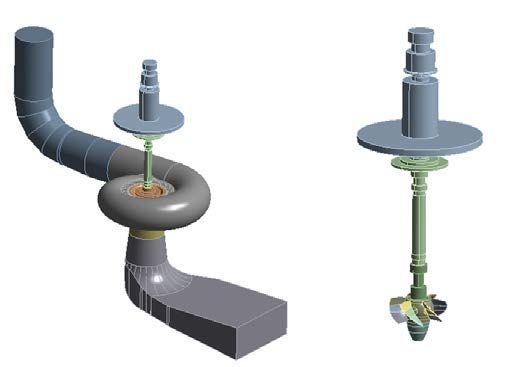
30th IAHR Symposium on Hydraulic Machinery and Systems IOP Publishing
IOP Conf. Series: Earth and Environmental Science 774 (2021) 012057 doi:10.1088/1755-1315/774/1/012057

2. Description of the reduced scale Kaplan turbine
 The present test case is a Kaplan turbine model which is located at the Vattenfall Research and
Development Facility in Älvkarleby, Sweden. The model turbine is a 1:3 reduced scale of an existing
prototype in a nearby power station and operates in a closed-loop configuration.
 The turbine model is composed of 6 runner blades, 20 equally distributed guide vanes and 18
unequally distributed stay vanes with a runner diameter of 0.5 m. The nominal operating parameters of
the turbine model are: i) a head of 7 m, ii) a discharge of 0.71 m3/s and iii) a rotational speed of 696.3
rpm.
 In Fig. 1, a general view of the Kaplan model with the bearing details is shown together with the
hydraulic circuit. The runner blade bearing, highlighted in red on the left of Figure 1, is a double ball
bearing system which allows the adjustment of the pitch angle. The turbine bearing, highlighted in green,
is a roller bearing which only restricts the radial displacements. Finally, the inertial wheel bearing,
highlighted in blue, is a ball bearing which restricts all displacements, axial and radial.

 Figure 1. Kaplan turbine with the bearing details (left) and general view of the model (right).

3. Numerical model
 The fluid added mass is usually considered an inviscid phenomenon and modelled by a constant
coefficient for small motions [2]. In the field of the hydraulic turbines, the use of structural elastic
elements coupled with potential flow elements have been successfully used to capture the added mass
effect. It has been demonstrated that, for either blades or turbines, the natural frequencies measured
experimentally and calculated numerically by considering the fluid as a potential flow are in good
agreement [3]. In [4, 5, 6], the natural frequencies of submerged disk-like structures were also calculated
with high accuracy using potential flow elements coupled with structural ones.
 The pressure wave equation together with the structural equation have been used to carry out the
coupled acoustic-structural modal analysis of the Kaplan turbine test stand based on Equation 1:

 [ ] ̈ + [ ] = [ ]
 � (1)
 � � ̈ + � � = − [ ] ü

where [ ] and � � are the structural and fluid mass matrices, respectively, [ ] and � � are the
structural and fluid stiffness matrices, respectively, [ ] is the coupling matrix, is the pressure, is the
fluid density and is the structural displacement.

 2
30th IAHR Symposium on Hydraulic Machinery and Systems IOP Publishing
IOP Conf. Series: Earth and Environmental Science 774 (2021) 012057 doi:10.1088/1755-1315/774/1/012057

3.1. Finite element model
 Two different numerical models have been built, the first one includes the runner, the shaft and the
surrounding water which is contained between the penstock, spiral casing, distributor, runner water
passage and draft tube, see left of Fig. 2. The second one only includes the structural components: the
shaft, up to the connection with the generator, and the runner, see right of Fig. 2.

Figure 2. Model of the Kaplan turbine test stand with the rotor and the surrounding fluid domain (left)
 and only with the rotor in vacuum (right).

3.2. Boundary conditions

3.2.1. Structural boundary conditions
 The turbine bearing has been modelled by a connection that allows axial displacements but restricts
the radial ones whereas the inertia wheel bearing is modelled by a connection that restricts the
displacements in all directions.
 The runner blade bearings have been modelled by using a bushing contact whose stiffness value can
be modified.

3.2.2. Acoustic boundary conditions
 The nodes of the fluid domain in contact with the runner are defined as fluid structure interaction
interface, which means that these surfaces satisfy the non-penetrative condition of the fluid in the
structure as well as the kinematic and dynamic continuity.
 The nodes of the fluid domain in contact with static walls are fixed, thus neither displacements nor
absorptions of the acoustic wave energy are permitted.
 Finally, the penstock inlet and draft tube outlet have been defined with a prescribed relative pressure
of 0 Pa.

4. Results

4.1. Added Mass
 The added mass effects have been investigated with two numerical modal analyses of the turbine at
rest. One analysis with the turbine in vacuum and another one with the turbine in water, see Fig. 2.
 The reductions of natural frequencies have been quantified using the frequency reduction ratio (FRR)
coefficient defined by Equation 2:

 −
 (%) = (2)

where Wv is the natural frequency of the structure in vacuum and Ww in water.

 3
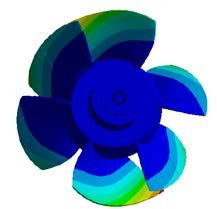
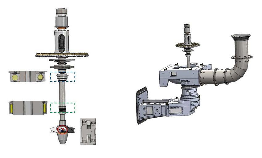
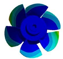
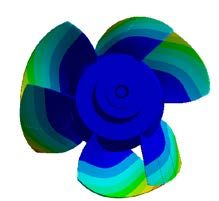
30th IAHR Symposium on Hydraulic Machinery and Systems IOP Publishing
IOP Conf. Series: Earth and Environmental Science 774 (2021) 012057 doi:10.1088/1755-1315/774/1/012057

 It has been considered that the maximum periodic excitation frequency to be taken into account is
the guide vane passing frequency which is approximately 250 Hz. Therefore, the frequency range in the
present study has been set between 0 and 300 Hz. It is important to notice that within this range there
are no runner’s natural frequencies. That is why the first family of natural frequencies of the runner has
been studied separately.
 In Table 1 the natural frequencies of the first 5 modes are indicated in vacuum and water, as well as
the corresponding FRRs. It can be observed that the added mass is almost negligible for most of the
modes. The invariance between the natural frequencies of the turbine in vacuum and in water can be
explained by the fact that the fluid mass affected by the displacement of the rotor is almost negligible
compared to the total modal mass. In particular, only M3 is affected by the added mass with a FRR of
about 12.5 %.
Table 1. Natural frequencies of the turbine rotor in vacuum and in water with the corresponding FRRs.
 M1 M2 M3 M4 M5
 Turbine in vacuum (Hz) 28 55 97 271 281
 Turbine in water (Hz) 28 55 85 271 281
 FRR (%) 0 0 12.5 0 0

 In Fig. 3, the mode shapes of the turbine for the first five (5) modes with natural frequencies below
300 Hz are plotted.

 M1 M2 M3 M4 M5

 Figure 3. First five (5) mode shapes of the Kaplan turbine rotor.

 The natural frequencies of the runner itself have been classified in families in which blades share the
same mode shape topology following [7]. In Table 2, the natural frequencies of the first four (4) modes
of the bending family are listed.

 Table 2. Natural frequencies of the runner modes bending family in vacuum and in water with the
 corresponding FRRs.
 B1 B2 B3 B4
 Runner in vacuum (Hz) 923 924 960 1030
 Runner in water (Hz) 466 473 499 585
 FRR (%) 49.5 49.0 48.0 43.0

 For the natural frequencies with mode shapes mainly affecting the runner, the impact of the added
mass is much more important than the ones which have displacement fields affecting both runner and
shaft as it can bee seen in Table 2 and 1, respectively.
 In Fig. 4, the mode shapes of the runner modes bending family are plotted.

 4
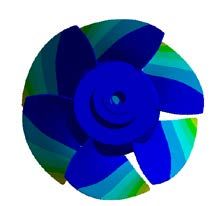
30th IAHR Symposium on Hydraulic Machinery and Systems IOP Publishing
IOP Conf. Series: Earth and Environmental Science 774 (2021) 012057 doi:10.1088/1755-1315/774/1/012057

 B1 B2 B3 B4

 Figure 4. Mode shapes of the banding family.

4.2. Turbine rotational speed
 In this section, the impact of the turbine rotational speed on the natural frequencies of the Kaplan
model in vacuum is presented. In this case, 10 modal analyses have been carried out when increasing
the rotational speed from 0 to 1500 rpm which covers most of the operational range of the test stand.
Then, the evolution of the natural frequencies as a function of the rotational speed has been studied.
 In Fig. 5, the natural frequencies of M1 and M5, which are most sensitive to the rotational speed,
have been plotted as a function of the rotational speed. It can be concluded that the more bent the rotating
shaft is, the higher the impact of the rotational speed on the natural frequencies.
 In Table 3, the maximum variation of the natural frequencies for each mode shape is indicated. It is
interesting to observe that for M1 the split of the natural frequency is symmetrical whereas this
symmetry is lost in M5.

 Figure 5. Black lines (M1) and dashed lines (M5).

 Table 3. Maximum variation of the natural frequencies of M1 and M5 due to the rotational speed.
 0 rpm 1500 rpm Maximum Variation (%)
 25 10.7
 M1 28
 31 10.7
 268 4.6
 M5 281
 298 6.0

 5
30th IAHR Symposium on Hydraulic Machinery and Systems IOP Publishing
IOP Conf. Series: Earth and Environmental Science 774 (2021) 012057 doi:10.1088/1755-1315/774/1/012057

4.3. Runner blade bearing
 In this section, the sensitivity of the turbine natural frequencies in water to the variation of the runner
blade bearing stiffness is presented. The water head modifies the blade bearing stiffness which alters the
modal response of the Kaplan turbine model. Therefore, three modal analyses with blade bearing
stiffnesses corresponding to heads of 17.6, 7 and 2.3 mwc have been carried out with 17.6 and 2.3 mwc
being the highest and lowest possible head configurations for the turbine model and 7 mwc being the
nominal head.
 Only the mode shapes primarily affecting the runner are influenced by this variable. The study has
therefore only been focused on the natural frequencies of the runner modes bending family. In Table 4,
it can be observed that the maximum variation of the natural frequencies decreases for higher modes.

 Table 4. Natural frequencies of the bending family runner modes for different water heads.
 17.6 mwc 7 mwc 2.3 mwc Maximum variation (%)
 B1 473 466 454 4
 B2 479 473 460 4
 B3 503 499 489 3
 B4 588 585 581 1

5. Summary of the results
 The impact on the natural frequencies of the added mass, the rotational speed and the runner blade
bearing stiffness are summarized in Table 5 for comparison by presenting the maximum variation of the
natural frequencies. It can be observed that the variable which causes the highest variation of the natural
frequencies of the Kaplan turbine model is the added mass. And in this case, the most affected mode
shapes are the ones with displacements of the runner.

 Table 5. Impact of different phenomena on the change of natural frequencies of a Kaplan turbine
 model.
 Maximum Variation (%)
 Added Mass 49.5
 Rotational Speed 10.7
 Runner Blade Bearings 4.0

6. Conclusion
 In the present paper, the impact of the added mass, the turbine rotational speed and the runner blade
bearing stiffness on the modal response of the reduced scale Kaplan turbine has been investigated.
 With regard to the added mass, it has been observed that for the first mode shapes of the whole
turbine rotor, which primarily show shaft displacements, the impact of the surrounding water can be
considered negligible. This is consistent with the definition of added mass because the amount of water
mass entrained by the first mode shapes is negligible compared to the modal structural mass. However,
the natural frequencies with significant displacements at the runner are strongly reduced because of the
added mass reaching maximum reductions of about 50%.
 Regarding the turbine rotational speed, the maximum variation of a natural frequency between the
turbine at rest and with a rotating speed of 1500 rpm is of about 11 %.
 Concerning the modification of the runner blade bearing stiffness due to the change of the turbine
head, it has been found a maximum variation of 4%.
 In conclusion, the largest variations of the runner natural frequencies will be induced by the added
mass when the turbine is submerged in water.

 6
30th IAHR Symposium on Hydraulic Machinery and Systems IOP Publishing
IOP Conf. Series: Earth and Environmental Science 774 (2021) 012057 doi:10.1088/1755-1315/774/1/012057

Acknowledgments
 This project has received funding from the European Union's Horizon 2020 research and innovation
programme under grant agreement No 814958. The authors also wish to acknowledge Vattenfall for the
technical support received for developing this work.

References
[1] Trivedi C, (2017). A review on fluid structure interaction in hydraulic turbines: A focus on
 hydrodynamic damping. Engineering Failure analysis, 1-22, 77.
[2] Grift E. J, Vijayaragavan N. B, Tummers M. J, Westerweel J, (2019). Drag force on an
 accelerating submerged plate. Journal of Fluid Mechanics, 369-398, 866.
[3] Gauthier J, Giroux A. M, Etienne S, Gosselin F.P, (2017). A numerical method for determination
 of flow-induced damping in hydroelectric turbines. Journal of Fluids and Structures , 341-
 354, 69.
[4] Presas A, Valentin D, Egusquiza E, Valero C, Seidel U, (2015). On the detection of natural
 frequencies and mode shapes of submerged rotating disk-likle structures from the casing.
 Mechanical Systems and Signal Processing, 547-570, 60.
[5] Presas A, Valentin D, Valero C, Egusquiza M, Egusquiza E, (2019). Experimental measurements
 of the natural frequencies and mode shapes of rotating disk-blades-disk assemblies from the
 stationary frame. Applied Sciences, 9(18).
[6] Valentín D, Presas A, Egusquiza E, Valero C (2016). On the Capability of Structural-Acoustical
 Fluid-Structure Interaction Simulations to Predict Natural Frequencies of Rotating Disklike
 structures Submerged in a Heavy Fluid. Journal of Vibration and Acoustics, 138(3).
[7] Takaffoli M, Yousefi-Koma A, Mahjoob M, Shahsavari A, Vaezi A. M, Safa M, Khoshnavaz H,
 (2010). Experimental and Finite Element Modal Analysis of a Bladed Disk. AERO2010-3978.

 7
You can also read