On the Influence of Mean Shear Stress on Multiaxial High Cycle Fatigue of Metallic Materials
←
→
Page content transcription
If your browser does not render page correctly, please read the page content below
Materials Research. 2021; 24(1): e20200319
DOI: https://doi.org/10.1590/1980-5373-MR-2020-0319
On the Influence of Mean Shear Stress on Multiaxial High Cycle Fatigue of Metallic
Materials
Tiago Lima Castroa , Marcos Venicius S. Pereiraa , Fathi Aref Darwishb
a
Pontifícia Universidade Católica do Rio de Janeiro, Departamento de Engenharia Química e de
Materiais, Rua Marques de São Vicente, 22453-900 Rio de Janeiro, RJ, Brasil
b
Universidade Federal Fluminense, Engenharia Civil, Rua Passo da Pátria, 24210-240, Niterói, RJ,
Brasil
Received: July 16, 2020; Revised: October 31, 2020; Accepted: November 11, 2020
A study has been made of the influence of a superimposed mean shear stress on the capability
of some multiaxial high cycle fatigue criteria to predicting fatigue behavior of 42CrMo4 and 34Cr4
alloy steels. Five selected critical plane-based criteria, namely Matake (M), Susmel & Lazzarin (S&L),
Findley (F), Carpinteri & Spagnoli (C&S) and Liu & Mahadevan (L&M), were applied to a number of
published experimental fatigue resistance limit tests, involving synchronous sinusoidal in-phase and
out-of-phase bending and torsion. Applying to the same loading conditions a mesoscopic scale-based
criterion proposed by Papadopoulos (P), one could verify that predictive capability of such an approach
is almost invariably superior to those associated with the M, S&L, F, C&S and L&M models. As the
Papadopoulos criterion is independent of mean shear stress, it seems appropriate to conclude that the
inclusion of such a stress as loading parameter in the critical plane-based models does, in fact, exert
a negative influence on their predictive capability. Finally, it is worth mentioning that, except for the
Matake, S&L and L&M criteria, the other critical plane-based criteria exhibit a dependence of the
fatigue resistance in pure torsion with respect to a superimposed mean shear stress, in disagreement
with well-established experimental observations.
Keywords: sinusoidal bending and torsion, critical plane, mesoscopic scale.
1. Introduction
Over many decades, a large number of multiaxial high group depend for their application on prior identification of
cycle fatigue damage criteria have been introduced aiming the critical plane where fatigue damage can occur leading
at predicting fatigue failure of metallic materials under to crack initiation. With the critical plane already identified,
time-varying multiaxial stresses. These criteria can be one can calculate the stresses acting on it as a result of
divided into three groups: stress-based, strain-based and the applied cyclic loads. In addition, practical mechanical
energy-based models1. For fatigue life extending over a very components, such as those mentioned above, may also
high number of cycles (theoretically infinite), the stresses experience superimposed mean (static) normal stress that
acting on mechanical components, such as railroad wheels, can strongly affect the fatigue limit of metallic materials.
crankshafts, axles and turbine blades, are kept within the More specifically, a tensile mean stress results in reducing
elastic limit and hence stress-based models are popularly the fatigue limit, whereas a compressive mean stress leads
used in high cycle fatigue analysis. Considering the whole to a net increase3. For uniaxial normal loading, these effects
stress space to be divided into two parts, namely safe and can be taken into account, for example, by using Gerber’s
unsafe, the safe part containing the origin is to be bounded parabola or Goodman’s diagram7. For multiaxial high cycle
by a closed surface and a given multiaxial fatigue criterion fatigue models belonging to the critical plane approach, mean
can thus be expressed in terms of an inequality, whose normal stress effect is included through its contribution to
satisfaction signifies that the stress state, induced by the the maximum normal stress acting on the critical plane6,8. In
external cyclic loading, will remain within the safe part of the case of superimposed mean shear stress, again its effect
the stress space. on multiaxial high cycle fatigue behavior is considered to be
Several reviews of some commonly used multiaxial the result of a contribution to the maximum normal stress
high cycle fatigue damage criteria, including stress-based acting on the critical plane. A firmly established experimental
models, can be found in the literature2-6. As can be verified observation, though, refers to the fact that a superimposed
from these references, the stress-based approach englobes a mean static torsion has no effect on the fatigue limit of metals
large number of models that can be divided into four main subjected to cyclic torsion. That is, the amplitude of the
groups based on: equivalent stress, stress invariants, average shear stress that can be sustained by a specimen submitted
stress and critical plane stress. Models pertaining to the last to torsion for a very high number of cycles (theoretically
infinite) is unique9. However, for lower fatigue lives (e.g.
*e-mail: tiagocastrobl@gmail.com 105, 104), a mean stress reduces the amplitude of the shear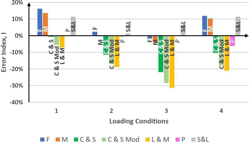
2 Castro et al. Materials Research
stress that can be sustained by the specimen through its At this point one should mention that the cited criteria
finite fatigue life3. This is valid as far as the yielding of the are all applicable to hard metallic materials whose ratio
specimen is not reached, that is the maximum shear stress between the endurance limit under fully reversed torsion
during cyclic torsion does not exceed the yield limit in shear. and that under fully reversed bending is in the range of
The present work was initiated with the purpose of 1 / 3 ≤ t−1 / f −1 ≤ 1 6. It is also important to point out that the
evaluating the influence of mean shear stress on the capability left-hand side (LHS) of the inequalities, given by Expressions
of a number of critical plane-based criteria to predict high 1 to 5, refers to the driving force for fatigue failure due to
cycle fatigue behavior of metallic materials under combined the stresses acting on the critical plane as a result of cyclic
bending and torsion. The loading conditions, to which the loading. The right-hand side (RHS), on the other hand, is
criteria were applied, were taken from published experimental related to the fatigue resistance of the material and therefore
fatigue resistance limit tests, involving synchronous sinusoidal a comparison between the two sides could indicate whether
in-phase and out-of-phase loadings. fatigue failure is likely to take place.
Another aspect to be dealt with in the study is to determine Application of any of the criteria mentioned above, to a
whether for a given model the fatigue resistance limit for given loading condition, depends in the first place on identifying
a pure torsion loading would be affected by the presence the critical plane. For the Matake and S&L criteria, the critical
of a superimposed mean shear stress. The inequalities plane is defined as the plane on which the shear stress amplitude
Ca attains its maximum. For the Findley criterion, the critical
representative of five selected models, namely Matake
plane is determined by maximizing the linear combination of
(M), Susmel & Lazzarin (S&L), Findley (F), Carpinteri &
the shear stress amplitude Ca and the maximum value of the
Spagnoli (C&S) and Liu & Mahadevan (L&M), are given
normal stress N max. As to the C&S and L&M criteria, the critical
respectively by Expressions 1 to 51,6,10-12
plane determination is based on knowing the fracture plane
Ca + µ N max ≤ t−1 (1) as well as the angle between the two planes, δ . The fracture
plane is defined as the plane on which the maximum principal
stress N max achieves its greatest value in the course of cyclic
N max
Ca + k ′ ≤ t−1 (2) loading1,6,13-15, and the angle δ is given by Equations 8 and 9
Ca
for the C&S and L&M criteria, respectively1,6
2
Ca + k N max ≤ f (3) t 3π
δ= 1 − −1 (8)
f −1 8
2
f
2
N max + −1 Ca2 ≤ f −1 (4)
1 1
t−1 2
−2 + 4 − 4 2 − 3 5 − 2 − 4s
1 −1 s s (9)
δ = cos
2 1
Nm
2
2 5 − 2 − 4s 2
Na 1 + η 2 s
f −1 Ca (5)
+ ≤λ
f −1 t−1
Table 1. Definition of pertinent material constants.
where Ca and N a are, respectively, the shear stress and t
µ 2 −1 − 1
normal stress amplitudes acting on the critical plane. N m is = f −1
the mean normal stress acting on the same plane and hence
N max will be given by k ′ t − −1
=
f
−1
2
= Na + Nm .
N max (6)
f
The constants µ , k ', k , f , η and λ are material parameters 2 − −1
which depend exclusively, as shown in Table 1, on the fatigue k= t−1
limits for fully reversed bending f −1 and fully reversed f
2 −1 − 1
torsion t−11,6,10-12. t−1
In addition to the five models presented above, a modified
version13 of the C&S criterion is also considered in the present f −21
f =
study. This modified version is simply obtained by replacing f −1
4
− 1
N max in Expression 4 by the parameter N a , eq given by t
−1
N f
N a ,= N a + f −1 m (7) 3 − −1
eq 3 1 t−1
σu η= +
4 4 3 −1
where σ u is the material’s ultimate strength. Accordingly,
the above equation takes into account the linear relationship
1/ 2
(proposed by Goodman7) between normal stress amplitude = λ cos 2 ( 2δ ) s 2 + sin 2 ( 2δ )
and normal stress mean value . 13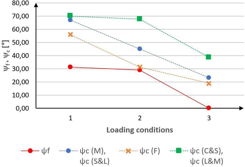
On the Influence of Mean Shear Stress on Multiaxial High Cycle Fatigue of Metallic Materials 3
where δ in Expression 9 is given as a function of s and s 1
refers to the ratio t−1 / f −1. In both expressions 8= and 9, δ is p sin (θ ) σ a sin ( 2ϕ ) + τ a cos ( 2ϕ ) cos ( β ) (13)
2
nil for −1 −1, which is the case of extremely hard metals
t = f
and is equal to π / 4 for t−1 / f −1 = 1 / 3 , which is the border q = − sin (θ )τ a sin ( β ) cos ( 2ϕ ) (14)
between hard and mild metals.
where θ is the angle between the vector normal to the
2. Literature Review: Critical Plane Stresses plane ∆ and the z -axis, and ϕ is the angle between the line of
Calculation of the stresses acting on the critical plane intersection of the x- y plane with the plane ∆ and the y-axis.
is summarized here for the case of synchronous sinusoidal As to the normal stresses acting on ∆, and N a are
biaxial normal and shear stress loading (Figure 1), defined expressed as Carpinteri and Spagnoli6
by the parameters σ a , τ a , σ m, τ m and β , where σ a and τ a are
respectively the applied normal and shear stress amplitudes, = N m sin 2 (θ ) σ m sin 2 (ϕ ) + τ m sin ( 2ϕ ) (15)
σ m and τ m are the corresponding mean stresses and β is
the phase difference between the bend and torsion stress =Na a 2 + b2 (16)
components.
Considering a general material plane ∆, the tip of the shear with
stress vector describes an elliptic path on the plane ∆ during
a cycle of synchronous sinusoidal out-of-phase bending = and a sin 2 (θ ) σ a sin 2 (ϕ ) + τ a cos ( β ) sin ( 2ϕ ) (17)
torsion . The radius of the minimum circumscribed circle
3,6
to the ellipse is equal to the ellipse’s major semi axis, and b = − sin 2 (θ ) τ a sin ( β ) sin ( 2ϕ ) . (18)
this corresponds to the shear stress amplitude Ca given by
Carpinteri and Spagnoli6 In regard to the dependence of N m and N a on θ , it is
clear that they attain their maximum levels for θ = π / 2
f 2 + g 2 + p2 + q2 f 2 + g 2 + p2 + q2
2 and consequently for the plane stress loading conditions
=Ca +
2
− ( fq − gp ) , (10)
2 2 considered here, the critical plane, where fatigue damage
can occur leading to crack initiation, is to be perpendicular
where f , g , p and q are auxiliary functions given by to the x- y plane.
Carpinteri and Spagnoli6 Figure 2 shows a general plane which is perpendicular
to the x- y plane, with its orientation uniquely defined by the
1 angle ϕ , or equivalently by its complementary angle ψ . N m
f sin ( 2θ ) σ a sin 2 (ϕ ) + τ a cos ( β ) sin ( 2ϕ ) (11)
2
and N a acting on this plane will thus be given in terms of ϕ as
1 = N m σ m sin 2 (ϕ ) + τ m sin ( 2ϕ ) . (19)
g = − sin ( 2θ )τ a sin ( β ) sin ( 2ϕ ) (12)
2
Figure 1. Plane stress loading conditions applied to the 42CrMo4 Figure 2. General material plane normal to the x-y plane with
and 34Cr4 alloy steels. its orientation defined by the angle ϕ or by its complementary ψ.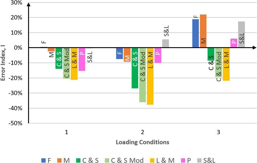
4                                                            Castro et al.                                                                 Materials Research

        Na
        =        a 2 + b2 ,                                         (20)

        with

=a σ a sin 2 (ϕ ) + τ a cos ( β ) sin ( 2ϕ )                        (21)

        b = −τ a sin ( β ) sin ( 2ϕ ) .                             (22)

        With the angle θ equivalent to π / 2, the two auxiliary functions
        f and g are nil and the shear stress amplitude will be given by
       Ca
       =         p2 + q2                                            (23)

        where
             1
=p             σ a sin ( 2ϕ ) + τ a cos ( β ) cos ( 2ϕ )            (24)
             2

        q = −τ a sin ( β ) cos ( 2ϕ )                               (25)

             Maximizing Ca with respect to the angle ϕ , which can
        be achieved by varying ϕ according to a given increment,
        one can determine the critical plane orientation ϕc as well
        as the corresponding Ca , N a and N m values. Both the Matake         Figure 3. Critical plane orientation ϕc and its relation to fracture
        and S&L criteria can thus be applied by substituting the              plane orientation ϕf in the C&S and L&M criteria.
        values obtained for a given loading condition in the LHS
        of Expressions 1 and 2. It is to be noted that, according to
        Equation 19, N m depends on τ m and hence the Matake and              to be the case for the Matake and S&L criteria where the
        S&L criteria are influenced by the presence of a mean shear           critical plane orientation for pure torsion loading is given
        stress component. This same procedure is also valid for               by ϕc = π / 2 , leading to the fact that N max will be nil and
        applying the Findley criterion, except for the fact that, instead     Ca will be given by τ a , which for “infinite” fatigue life
        of maximizing Ca, the LHS of the inequality representative            corresponds to t−1 , in accordance with the conclusion drawn
        of the criterion is to be maximized with respect to ϕ and             by Papadopoulos et al.3.
        the maximum value thus obtained is to be compared with                     In applying the Findley criterion, the LHS of Expression
        the RHS. As N max is related to N m by Equation 6 and as              3 has to be maximized with respect to the angle ϕ (Figure 2).
             depends on τ m (Equation 19), the Findley criterion is           For pure torsion loading, the stresses acting on a general
        likewise influenced by τ m.                                           material plane, whose orientation is given by angle ϕ , are
             The fracture plane orientation, ϕ f , depicted in Figure 3,      given by
        is determined by maximizing N max with respect to ϕ and               Ca = τ a cos ( 2ϕ )                                                               (28)
        therefore the critical plane orientation ϕc for both C&S
        and L&M criteria will be given, as shown in the figure, by             N max
                                                                                  =    (τ a + τ m ) sin ( 2ϕ )                                                  (29)
        ϕ=
         c ϕ f −δ                                                   (26)      and accordingly, the critical plane orientation, as defined by
        or equivalently by                                                    ϕc, can be expressed as

        ψ=                                                          (27)                       k (τ a + τ m )
         c ψ f +δ                                                              tan ( 2ϕc ) =                                                                    (30)
                                                                                                    τa
        where ϕ and ψ are complementary. As ϕc depends on τ m, the
        stresses N a, N m and Ca acting on the critical plane will do         and the Findley criterion for this type of loading reduces to
        likewise and both the C&S and L&M criteria are expected                                          2
        to be influenced by the presence of a mean shear stress                 τ a2 + k 2 (τ a + τ m ) ≤ f .                                                   (31)
        component.                                                            At the torsion fatigue limit, τ a is replaced by t−1 , thus yielding

        3. Calculation Procedures                                             t−1 =
                                                                                  −
                                                                                    k 2τ m
                                                                                           +
                                                                                                             k 4τ m2
                                                                                                                           −
                                                                                                                               k 2τ m2 − f 2
                                                                                                                                               .                (32)
                                                                                       (
                                                                                    1+ k2        ) (1 + k )       2
                                                                                                                       2
                                                                                                                                (1 + k )
                                                                                                                                       2

        3.1 Pure torsion loading
            As mentioned earlier, it is experimentally well established            This means that the Findley criterion predicts a dependence
        that a superimposed mean static torsion stress τ m has no             of the fatigue limit in pure torsion loading on a superimposed
        effect on the fatigue resistance limit of metals subjected to         mean torsion stress, τ m . For τ m = 0 , t−1 will be given by
        cyclic torsion9. That is, the amplitude of the shear stress in
                                                                                           f
        a pure torsion loading associated with a very high number             t−1 =                                                                             (33)
        of cycles should be unique and equal to t−13,9. This is seen                   1+ k2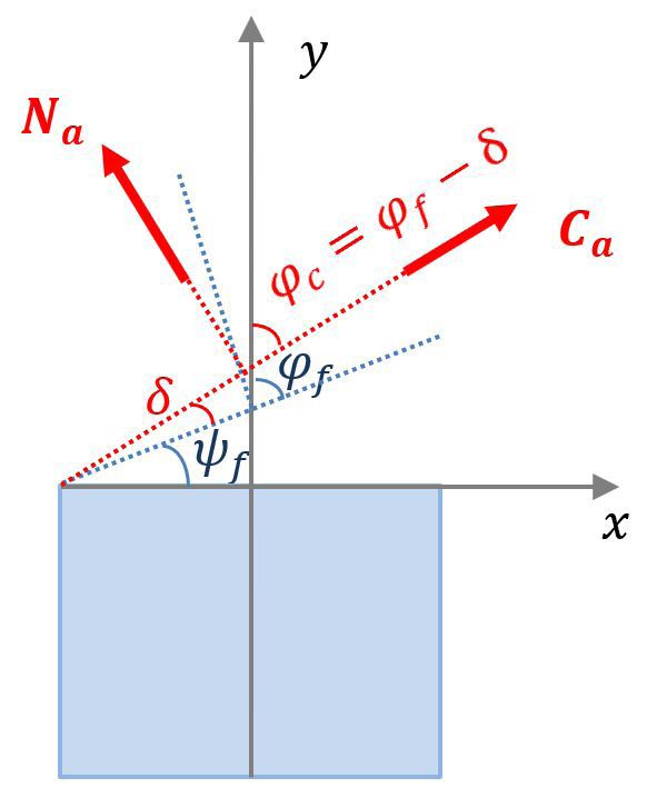
On the Influence of Mean Shear Stress on Multiaxial High Cycle Fatigue of Metallic Materials 5
Substituting for f and k (see Table 1), the RHS of the 2
τm
above equation yields t−1 . 1 + η cos ( 2δ ) =
1
f −1
The fracture plane orientation in pure torsion cyclic (44)
loading, ϕ f , is equivalent to π / 4 and hence the critical plane
that is
orientation in the C&S model will be given by
2 f −1
π cos ( 2δ ) = −
ϕc= −δ (34) ητ m
4 (45)
where δ , the angle between the two planes, is given by or
Equation 8. cos ( 2δ ) = 0.
The stresses Ca , N a and N m acting on the critical plane (46)
can thus be expressed in terms of δ as follows The first solution has to be discarded, considering the
Ca = τ a sin ( 2δ ) (35) fact that cos ( 2δ ) cannot be infinite for τ m = 0 . The other
solution implies in that s in Equation 9 has to be equivalent
N a = τ a cos ( 2δ ) (36) to 1 / 3 , meaning that the fatigue resistance limit in pure
torsion t−1 is a fixed fraction of the fatigue limit in normal
N m = τ m cos ( 2δ ) .
stress loading f −1.
(37)
The variation of the fatigue resistance limit in pure
Substituting Ca and N max in the LHS of Expression 4, torsion loading t−1 with the mean shear stress τ m is presented
and replacing τ a by t−1 for the fatigue limit state, one obtains in Figure 4, for the Findley, C&S and modified C&S models.
The curves shown in this figure were all obtained for a hard
( t−1 + τ m )2 cos2 ( 2δ ) + f −21sin 2 ( 2δ ) =
f −1 (38) steel, where f −1, t−1 and σ u are given, respectively, by 313.19,
196.2 and 704.1MPa .
which finally yields Specifically, with regard to the Findley criterion, Figure 4
indicates that t−1 starts to decrease at a slow rate and as τ m
t=
−1 f −1 − τ m (39)
assumes higher levels, the reduction in t−1 turns out to be
meaning that the C&S criterion predicts a dependence of more significant.
t−1 on a superimposed mean torsion stress τ m.
Considering the modified C&S criterion, N max is to be 3.2 Combined bend and torsion loading
replaced by N a, eq given by Equation 7. Accordingly, at the In an effort to evaluate the influence of τ m on the
fatigue resistance limit for pure torsion loading, the modified applicability of the selected models, a number of experimental
C&S criterion yields the following relation constant amplitude cyclic loading conditions encountered in
the literature16 were considered. They involve synchronous
2 f2 2
2 f
t−1 cos ( 2δ ) + −21 τ m cos ( 2δ ) + 2t−1τ m −1 cos ( 2δ ) + f −1 sin ( 2δ ) =
2 2 2 2
f −1 (40) sinusoidal in-phase and out-of-phase bending and torsion
σu σu
applied to two alloy steels, namely 42CrMo4 and 34Cr416,
which eventually reduces to and they correspond to the fatigue limit state above which
fatigue failure occurs and below which fatigue-life extends
f −1
t−1 + τm =
f −1 (41) over a very high number of cycles (theoretically infinite
σu life). As presented in Tables 2 and 3, the loading parameters
that is, include both stress amplitudes and mean shear stress,
together with the phase difference between the normal and
τ
t−1 f −1 1 − m
= (42) shear stress components. The ultimate tensile strength and
σu
fatigue resistance limits ( f −1 and t−1 ) are also listed in the
indicating that, here again, the modified C&S criterion same tables.
predicts a dependence of t−1 on τ m.
As to the L&M criterion, it can also be applied for pure
torsion loading by substituting the stresses Ca, N a and N m ,
given respectively by Equations 35, 36 and 37, in Expression 5.
Here the angle δ is calculated using Equation 9. As a result
of this substitution, one obtains the following relation:
2
cos ( 2δ )
τ a cos ( 2δ ) 1 + η 2
f −1 τ a sin ( 2δ )
+ ≤ λ. (43)
f −1 t−1
Again, for the fatigue limit state in pure torsion, τ a is Figure 4. Variation of the fatigue resistance limit in pure torsion,
replaced by t−1 and one eventually gets the following expression t−1, with the mean shear stress, τ m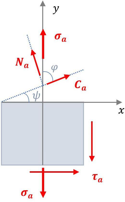
6 Castro et al. Materials Research
Table 2. Loading Conditions applied 42CrMo4.
f −1 = 398 [ MPa ] t−1 = 260 [ MPa ] σ u = 1025 [ MPa ]
Loading Condition σ a [ MPa ] σ m [ MPa ] τ a [ MPa ] τ m [ MPa ] β [ °]
1 266 0 128 128 0
2 283 0 136 136 90
3 333 0 160 160 180
Table 3. Loading conditions 34Cr4.
f −1 = 410 [ MPa ] t−1 = 256 [ MPa ] σ u = 795 [ MPa ]
Loading Condition σ a [ MPa ] σ m [ MPa ] τ a [ MPa ] τ m [ MPa ] β [ °]
1 316 0 158 158 0
2 314 0 157 157 60
3 315 0 158 158 90
4 355 0 89 178 0
As pointed out earlier, the criteria in question are to
be applied by substituting N a , N m and Ca acting on their
respective critical planes in their respective inequalities.
The error index I , which refers to the relative difference
between the two sides of the inequality, can be estimated as
LHS − RHS
=I × 100. (47)
RHS
An error index-based comparison between the models in
question can thus be made in terms of conventional fatigue
limit state under multiaxial loading. With the error index I
tending to zero, a given criterion is considered to be in good
agreement with the experiment carried out for a set of cyclic
bend and torsion loading. Positive I values, on the one hand, Figure 5. Fracture plane and critical plane orientations, ψ f and
are indicative of fatigue failure in a situation where failure ψ c , obtained on applying the criteria in question to the 42CrMo4
is not observed and hence the criterion is considered to be loading conditions.
conservative. Negative I values, on the other hand, indicate
that an adopted criterion is non-conservative, as it may permit
an increase in the applied cyclic loads thus leading to higher
risk of fatigue failure17.
4. Results and Discussion
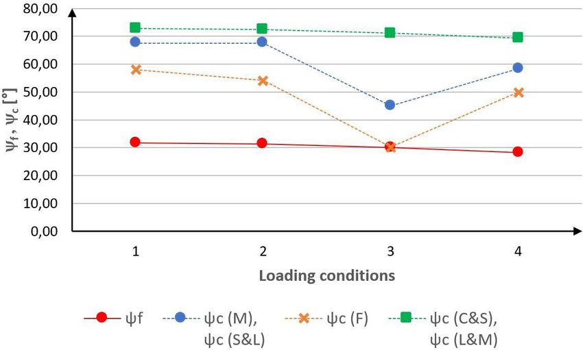
The fracture and critical plane orientations defined by
the angles ψ f and ψ c are presented in Figures 5 and 6, for
the combined bend and torsion loadings (Tables 2 and 3)
applied, respectively, to the 42CrMo4 and 34Cr4 steels.
Whereas the fracture plane orientation corresponding to
a given loading condition is unique for all the models in
Figure 6. Fracture plane and critical plane orientations, ψ f and
question, the critical plane orientation as expected does vary ψ , obtained on applying the criteria in question to the 34Cr4
c
from one model to another. loading conditions.
The values of the error index I obtained upon applying
the Matake, Findley, S&L, C&S, modified C&S and L&M
criteria to the loading conditions in question are presented σ a2 σ +σm (48)
in Figures 7 and 8. These figures also exhibit the I values + τ a2 + α a ≤ t−1
3 3
associated with applying, to the same loading coditions, a
mesoscopic scale-based model developed by Papadopoulos et al.3 where
and Papadopoulos18,19. The inequality representative of the
Papadopoulos criterion is expressed in terms of the applied = 3t
α −1 − 3 (49)
stress amplitudes and mean normal stress as given by f −1 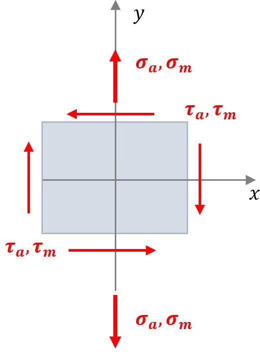
On the Influence of Mean Shear Stress on Multiaxial High Cycle Fatigue of Metallic Materials                  7

                                                                          Figures 7 and 8, to an error index that varies between −7%
                                                                          and 19%. Again, this is a range which is wider compared to
                                                                          that of −1% to 11% reported for fully reversed bending and
                                                                          torsion3, indicating negative influence of mean shear stress on
                                                                          the predictive capability of the Findley criterion. However, as
                                                                          the error indices corresponding to five of the seven loading
                                                                          conditions are situated within the ±10% range, the criterion
                                                                          can be considered to possess fairly good capability.
                                                                               As to C&S, modified C&S and L&M criteria, they
                                                                          invariably result in negative I values that can be as low
                                                                          as −38% and as high as −1% (Figures 7 and 8). For fully
                                                                          reversed bend and torsion loading, the corresponding I
                                                                          values are limited to the range between −2% and 9% 3,17.
Figure 7. Error Index values associated with applying the criteria        Accordingly, one may conclude that the presence of mean
to the 42CrMo4 loading conditions.                                        shear stress has a highly negative effect on the efficacy of
                                                                          these criteria to predicting high cycle fatigue behavior of
                                                                          metallic materials. Figures 7 and 8 also indicate that, with
                                                                          the exception of only four individual I values, the remaining
                                                                          17 are significantly situated below the −10% limit, meaning
                                                                          fairly poor predictive capability for the three criteria in
                                                                          the presence of mean shear stress. Comparing the L&M
                                                                          and C&S criteria, it is seen that the index predicted by the
                                                                          former is considerably more negative than that obtained by
                                                                          applying the latter to the same loading conditions. The use
                                                                          of the modified C&S criterion results in approximating the
                                                                          two indices to one another.
                                                                               In regard to the Papadopoulos criterion, the I values
                                                                          resulting from its application to the loading conditions
Figure 8. Error Index values associated with applying the criteria        in question were found to vary between −15% and 6%
to the 34Cr4 loading conditions.                                          (Figures 7 and 8), indicating predictive capability that is
                                                                          far more superior to that associated with applying the C&S
                                                                          and L&M models. Compared to Matake, Findley and S&L
     An important feature of the Papadopoulos criterion
                                                                          criteria, Papadopoulos’ continues to be considerably superior
refers to the fact that it is not influenced by the presence of
                                                                          for the case of the 34Cr4 alloy steel, where the I values
a superimposed mean shear stress and that it is applied by
                                                                          resulting from applying the criterion are close to nil except
simply substituting σ a, τ a and σ m, corresponding to a given
                                                                          for one loading condition, where the error index amounts to
loading condition, in Expression 48. However, its validity is
                                                                          approximately −6%. Only for one loading condition applied
limited to metals for which the inequality 1 / 3 ≤ t−1 / f −1 ≤ 0.8       to the 42CrMo4 steel does the Papadopoulos criterion result
is satisfied3.                                                            in an error index of about −15% which is lower than those
4.1 Discussing the error index                                            obtained with the Matake, Findley and C&S criteria (Figure 7).
                                                                               Finally, it is important to point out that the predominance
     The application of the Matake criterion to the seven                 of highly negative I values signifies that the use of C&S and
loading conditions in question is associated with I values                L&M criteria in the presence of mean shear stress leads to
ranging from −9% to 22% (Figures 7 and 8). This range is much             non-conservative assessment of the cyclic loading conditions
wider than the range of −6% to 8% , normally encountered for              and this may permit an increase in the applied loads and
combined fully reversed bend and torsion loading where no                 hence higher risk of fatigue failure.
mean shear stress is applied3. One may thus conclude that
the presence of a mean shear stress component could have
                                                                          5. Conclusions
a negative effect on the predictive capability of the Matake
criterion. An important observation, though, refers to the                    In view of the study carried out in the present work, the
fact that for five of the loading conditions, the corresponding           following conclusions can be drawn:
I values are situated in the −10% to 10% range, signaling                     1. Except for the Matake, S&L and L&M criteria, the
fair predictive capability of the criterion in the presence of                     critical plane-based models proposed by Findley
mean shear stress.                                                                 and C&S, incorrectly predict a fatigue resistance
     With I values varying from 0% to 17% (Figures 7 and 8),                       limit in pure torsion that depends on the mean shear
the S&L criterion is shown to be conservative. For four                            stress. However, according to L&M the fatigue
of the loading conditions, the corresponding error indices                         limits in torsion and bending are at a constant ratio
belong to the range ±10%, indicating fairly good capability                        of 1 / 3 for all metals. This is in disagreement with
for the criterion.                                                                 experimental observations which indicate a t−1 / f −1
     As to the Findley criterion, its application to the                           ratio that varies from 0.5 for mild metals to 1 for
seven loading conditions in question leads, as depicted in                         brittle metals.
8 Castro et al. Materials Research
2. For combined bending and torsion, the mean shear 4. Wang YY, Yao WX. Evaluation and comparison of several
stress is one of the loading parameters that define multiaxial fatigue criteria. Int J Fatigue. 2004;26(1):17-25.
the maximum normal stress acting on the critical 5. You BR, Lee SB. A critical review on multiaxial fatigue
assessments of metals. Int J Fatigue. 1996;18(4):235-44.
plane and this in turn influences the capability of
6. Carpinteri A, Spagnoli A. Multiaxial high-cycle fatigue criterion
the models to predict fatigue behavior.
for hard metals. Int J Fatigue. 2001;23(2):135-45.
3. The Papadopoulos criterion, which does not depend 7. Schijve J. Fatigue of structures and materials. Delft: Springer;
on mean shear stress, possesses predictive capability 2009.
that is far more superior to those associated with 8. Fatemi A, Socie DF. A critical plane approach to multiaxial
applying the C&S and L&M models, in the presence fatigue damage including out of phase loading. Fatigue Fract
of mean shear stress. Eng Mater Struct. 1988;11(3):149-65.
4. Compared to the Matake, S&L and Findley criteria, 9. Sines G. Behavior of metals under complex static and alternating
Papadopoulos’ is considered to be more precise stresses. In: Sines G, Waisman JL, editors. Metal fatigue. New
York: McGraw-Hill; 1959. p. 145-69.
in predicting high cycle fatigue behavior under
10. Matake T. An explanation on fatigue limit under combined
combined bend and torsion loading, in the presence stress. Bull JSME. 1977;20(141):257-63.
of mean shear stress. 11. Findley WN. A theory for the effect of mean stress on fatigue
5. Finally, it seems appropriate to propose that, in the of metals under combined torsion and axial load or bending. J
presence of mean shear stress, multiaxial high cycle Eng Ind. 1959;81(4):301-5.
fatigue behavior can be more safely evaluated by 12. Susmel A, Lazzarin P. A bi-parametric Wöhler curve for high
adopting mesoscopic scale-based approach rather cycle multiaxial fatigue assessment. Fatigue Fract Eng Mater
than the critical plane-based criteria considered in Struct. 2002;25(1):63-78.
the present study. 13. Carpinteri A, Spagnoli A, Vantadori S, Bagni C. Structural
integrity assessment of metallic components under multiaxial
fatigue: the C-S criterion and its evaluation. Fatigue Fract Eng
6. Acknowledgements Mater Struct. 2013;36(9):870-83.
14. McDiarmid DL. Fatigue under out-of-phase bending and torsion.
This research was developed within the scope of the
Fatigue Fract Eng Mater Struct. 1987;9(6):457-75.
Research and Technological Development of the Brazilian
15. Carpinteri A, Brighenti R, Spagnoli A. A fracture plane approach
Electric Energy Sector Program regulated by ANEEL, with in multiaxial high cycle fatigue of metals. Fatigue Fract Eng
the support of the Eneva Companies - Pecém II Energy Mater Struct. 2000;23(4):355-64.
Generation S.A., Itaqui Energy Generation S.A., Parnaíba 16. Zenner H, Heidenreich R, Richter IZ. Dauerschwing Festigkeit bei
Energy Generation and Commercialization S.A. and Parnaíba nichtsynchroner mehrachsinger beanspruchung. Werkstofftech.
II Energy Generation S.A. 1985;16(3):101-12.
17. Pereira MV, Darwish FA, Teixeira MC, Gonçalves RA.
Multiaxial high cycle fatigue criteria based on fracture plane
7. References identification: applicability to metallic materials. J Mater Eng
1. Liu Y, Mahadevan S. Multiaxial high-cycle fatigue criterion and Perform. 2019;28(8):4740-80.
life prediction for metals. Int J Fatigue. 2005;27(7):790-800. 18. Papadopoulos IV. Critical plane approach in high cycle fatigue:
2. Garud YS. Multiaxial fatigue: a survey of the state-of-the-art. on the definition of the amplitude and mean value of the shear
J Test Eval. 1981;9(3):165-78. stress acting on the critical plane. Fatigue Fract Eng Mater
3. Papadopoulos IV, Davoli P, Gorla C, Filippini M, Bernasconi Struct. 1998;21(3):269-85.
M. A comparative study of multiaxial fatigue criteria. Int J 19. Papadopoulos IV. Long life fatigue under multiaxial loading.
Fatigue. 1997;19(3):219-35. Int J Fatigue. 2001;23(10):839-49.You can also read