Introduction to Structural Geology - Workbook 2 Stereonets - Contents - School of Earth and Environment ...
←
→
Page content transcription
If your browser does not render page correctly, please read the page content below
School of Earth and Environment
                                  Contents

Introduction to
Structural Geology
Workbook 2 Stereonets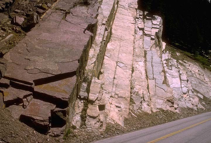
School of Earth and Environment
                                                  Contents

Contents
Introduction to stereonets					               4
Stereonet terminology					 6
Setting up a stereonet					                   7
1. Plotting a plane						                     8
2. Plotting a lineation						11
3. Plotting a pole						15
4. Pi-plots and folds on stereonets			       17
5. Restorations							23
6. Reading measurements from a stereonet		   27
Practical exercises						29
Acknowledgements and references			           43

                                                             2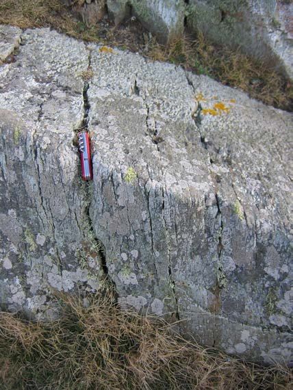
School of Earth and Environment
                                                                                                         Contents

How to use this workbook
This worksheet aims to be a general introduction      The worksheet includes basic plotting exercises.
to stereonets that covers basic plotting and          Those already confident with plotting data
some of the more common uses of stereonets in         on stereonets may wish to skip these and
structural geology. By the end of this workbook       concentrate on the self-assessment exercises
and associated exercises you should understand        at the end of the workbook. Answers to the
what a stereonet is, why they are used in structure   plotting exercises can be found by clicking on a
geology and be confident in plotting, manipulating    reading. The correct answer is shown together
and interpreting data on a stereonet.                 with common plotting errors. The stereonet used
                                                      for the exercises is an equal area stereonet. A
                                                      blank stereonet is included on a seperate PDF.

                                                                                                                    3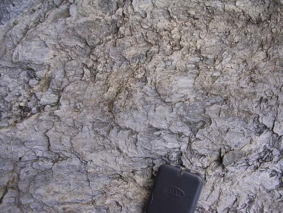
School of Earth and Environment
Contents
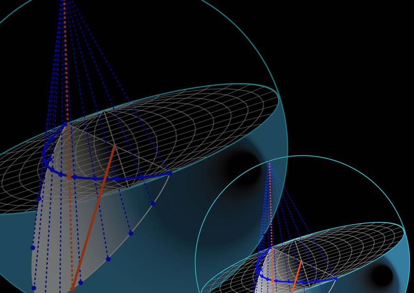
Introduction to stereonets Projection sphere
Projection plane
A stereonet is a lower hemisphere graph on to stereonet
which a variety of geological data can be plotted.
Stereonets are used in many different branches
of geology and can be used in a range of ways
beyond those which are discussed here (see Dipping plane
references for further uses). Stereographic
projection involves plotting 3D data (planar or
linear) on to a 2D surface (stereonet) where it Stereographic
can be manipulated and interpreted. projection of Figure 1a
dipping plane
Projection plane Spherical
Imagine a sphere with lines of latitude and stereonet projection of
dipping plane
longitude marked on it. A stereonet is the plane
of projection of the lower half of this sphere – it is
a lower hemisphere graph.
Imagine a plane cutting through the centre of
a lower hemisphere (figure 1a). The stereonet
forms the surface of this lower hemisphere.
Looking from above, where the plane touches Figure 1b
the edge of the lower hemisphere is an arc. This Spherical
projection of
arc is projected back up on to the stereonet to dipping plane
form a great circle (figure 1b). Figure 1c shows
the resulting plot.
Great circle of
dipping plane on
stereonet Figure 1c
4
School of Earth and Environment
                                                                                                                                                       Contents

                                                                                          Stereographic projection
                                                                                                of lineation
                                                                       Projection plane
                                                                          stereonet
Figure 2 shows this for a lineation. The lineation                                                                     Planes (e.g. bedding, cleavage, faults etc.) plot
lies on the plane (figure 2a), where it touches the                                                                    as great circles, and lineations (e.g. slickensides,
edge of the lower hemisphere is a point. This                                                                          bedding/cleavage lineations, fold axes etc.) plot
point is projected back up on to the stereonet as                                                                      as points.
a point (figure 2b). Figure 2c shows the resulting
plot. Notice how the lineation plots on the great                                                                      In this workbook, all stereonets will be plotted by
circle of the plane.                                                                                                   hand using card stereonets and tracing paper.
                                                                                                                       Why use card stereonets, with tracing paper and
                                                                                                           Figure 2b   drawing pins when data could be input straight
                                              Projection sphere
                                                                                                                       into a computer program or a smart phone app?
                                                                   Great circle of
                                                                  dipping plane on                                     The obvious reason is one needs to understand
 Projection plane
                                                                     stereonet
    stereonet                                                                                                          the theory behind stereonets to be able to
                                                                                                                       usefully interpret them and to recognise an
                                                                                                                       aberration in the output, which may be due to
                                                                                                                       an input/measurement error. This is best done
                                                                                                                       learning to plot by hand. In the field, for those
                                                                                                                       using notebooks, it is useful to be able to draw a
                                                                                                                       sketch stereonet to test a theory on the geometry
                                                                                                                       of a structure being mapped. Finally, working
                                                                                                                       with stereonets also helps develops 3D thinking,
                                              Figure 2a
                                                                                                                       an essential skill in structural geology.
             Intersection of lineation with
                   projection sphere                          Plot of lineation
                                                                                                           Figure 2c

                                                                                                                                                                         5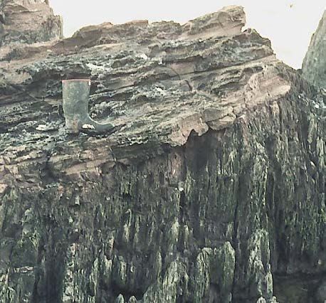
School of Earth and Environment
                                                                                                                                                         Contents

Stereonet terminology
                                       North pole                                                                       000° 010°
                                                                                                                                    020°
                                                                                                                                           030°
      Small circle                                                                                                                                040°
                                                                     Great circle
                                                                                                                                                     050°
                                                                                                                                                         060°

                                                                                                                                                            070°

                                                                                                                                                             080°
                                                                                               10° 30° 50°     70°    90°     70°     50° 30° 10° 090°
      Equator                                                               Equator     270°
                                                                                                  20° 40°  60°    80°     80°     60°    40° 20°

       Primitive

                                       South pole                                                                      180°

            Figure 3: Equal Area Stereonet (Schmidt): each of the sectors                   Figure 4: Equal Area Stereonet showing the degrees around
            has the same area.                                                              the primitive and across the equator.

Figure 3 shows the terminology used to describe            an equator across the middle. Great circles are        segments with a thicker ten degree lines (figure
the different parts of a stereonet. As a stereonet         longitudinal, whilst small circles are latitudinal.    4). Strikes and azimuths (bearings) are read
is a lower hemisphere it is described in a similar         The primitive is the outside of the stereonet.         around the primitive of the stereonet, dips and
way to a globe with north and south poles and              The stereonet grid is divided into two degree          plunges are read along the equator.
                                                                                                                                                                    6
School of Earth and Environment
Contents
Setting up a stereonet
Make a hole in the exact centre of the stereonet, Lay the tracing paper over the stereonet and Draw the outline of the stereonet on to the tracing
by pushing the drawing pin through from the push the drawing pin through it so that the paper paper. Mark on north, south, east, west or 000°,
front of the stereonet. Then remove the drawing freely rotates round the net 090°, 180°, 270° (figure 5).
pin and push it through the hole from the back.
North Outline of
stereonet on
Click below to watch our YouTube video: How to set up a stereonet
tracing paper
West East
Drawing pin
Tracing paper South
Figure 5: How to set up a stereonet
7School of Earth and Environment
Contents
Worksheet 1: Plotting a plane
Planes are measured using strike/dip and dip
direction (figure 6) (other methods of measuring
are used but this is the convention followed
at Leeds and so in the videos, exercises etc).
Examples of planes are bedding, faults, cleavage,
fold axial planes etc.
Strike
Strike: the line of the horizontal on a plane.
Dip
Measured from north in degrees and recorded
as three figures eg. 057
Dip: The maximum dip of a plane. Measured in
degrees from the horizontal and recorded as two
figures eg. 34. Perpendicular to the strike
Also need dip direction to fully describe the plane
eg SE
E.g. 057/34SE
Figure 6: Bedding planes dipping towards the road (Miller, 2012).
8School of Earth and Environment
Contents
How to plot a plane
000° ●● Strike/dip 090/40S 000°
●● Using a sharp pencil or
●● Mark on the strike - 090°
colour pencil, draw in the
great circle from the north pole
●● Note which way the plane is
270° 090°
through point to the south pole.
dipping, then rotate the tracing 270° 090°
paper round until this mark
is aligned with north on the
stereonet.
180° 180°
000° 000°
●● Find the great circle of the
●● Rotate the tracing paper
plane by counting in the angle
back to north. Check the
of dip along the equator from
plane is dipping in the correct
the primitive. Count in from
direction and admire your
090° the direction of dip as marked
270° 270° 090° work.
on the tracing paper (in this
case S). Mark with a dot.
180° 180°
9School of Earth and Environment
Contents
000°
270°
? 180°
090°
Click below to watch our YouTube video: How to plot a plane
Exercise:
Plotting planes on a stereonet
Plot the following planes on a stereonet
●● 032/20NW
●● 102/65S
●● 177/33E
●● 065/82NW
Click on the readings to see the answers
10School of Earth and Environment
Contents
Worksheet 2: Plotting a lineation
Lineations are measured using plunge/ azimuth. E.g. a lineation plunging at 45° towards 270°
Examples of lineations are slickensides and would be written: 45/270
slickenfibres on a fault surface (figure 7), fold
axes, mineral stretching lineation or ripple crests.
Plunge: The dip of a lineation as measured from
the horizontal. It is measured between 0-90°
and always recorded as two figures.
Azimuth: Azimuth is the direction of plunge. It is
a bearing and so measured between 0-360° and
recorded as three figures.
Azimuth
Plunge
Figure 7: Figure 8: Steeply plunging slickenfibres on a Figure 9: Gently plunging bedding-
Plunge and fault plane (J.Houghton). cleavage lineation (G.Lloyd) See page 14.
azimuth of a lineation.
11School of Earth and Environment
Contents
How to plot a lineation
000° ●● Plunge and azimuth: 25/225 000°
●● From the primitive count in
●● Mark on the azimuth reading the plunge 25°. Mark on the
270° 090° 090°
225° lineation
180° 180°
000° 000°
●● Rotate the tracing paper ●● Rotate the tracing paper
090° round until this mark is aligned
270° 090° back and admire your work.
with equator on the stereonet.
180° 180°
12School of Earth and Environment
Contents
000°
270°
? 180°
090°
Click below to watch our YouTube video: How to plot a lineation
Exercise:
Plotting lineations on a
stereonet
Plot the following lineations on a stereonet
●● 12/230
●● 73/345
●● 08/067
●● 34/102
Click on the readings to see the answers
13School of Earth and Environment
Contents
Lineations due to intersection of
two planes
Where two planes intersect a lineation is created On the stereonet the lineation is where the two the lineations on two different surfaces and
on one plane where the other plane cuts through great circles intersect. Notice how the bedding/ plotting them on the stereonet allows cleavage
it. Figure 10 shows a bedding/cleavage lineation cleavage lineation and the joint/cleavage lineation to be defined.
(where cleavage cuts bedding) and a joint/ lie on the cleavage plane. Cleavage planes can
cleavage lineation (where cleavage cuts the joint be difficult to measure in the field, but measuring
surface).
Bedding/cleavage 000°
intersection lineation
Cleavage
Joint/cleavage
intersection lineation
270° 090°
Joint
surface
Bedding
surface 180°
Figure 10: Relationship between three different surface (bedding, cleavage and jointing), their interesections
and how this is shown on a stereonet - see text for details
14School of Earth and Environment
Contents
Worksheet 3: Plotting a pole
The pole to a plane is an imaginary line ●● Plotting a pole to 055/20 SE ● Mark on the strike reading 055°
perpendicular to the plane (figure 11).
●● Note which way the plane is dipping, then rotate the
Poles are quicker to plot, more accurate, take up 000° tracing paper round until this mark is aligned with north on
less space and can reveal patterns more clearly the stereonet.
than plotting bedding as great circles.
●● Find the great circle of the plane by counting along the
A stereonet with poles is known as a Pi (π) plot. 270° 090° equator from the primitive. Count in from the direction of dip
as marked on the tracing paper (in this case SE) along the
equator line 20°.
●● Count a further 90° through the centre of the net and mark
180° a point – this is the pole to the plane
●● A faster method
000° is to count the dip 000°
from the centre
of the stereonet
along the equator
(automatically adds 090°
270° 090° 270°
90°)
Figure 11: The pole to a plane is an imaginary line ●● Rotate the tracing
perpendicular to that plane.
paper back and
180° admire your work. 180°
15School of Earth and Environment
Contents
000°
270°
? 180°
090° Click below to watch our YouTube video: How to plot a pole
Exercise:
Plotting poles on a stereonet
These are the same readings as in the
earlier exercise but here rather than plotting
as great circles plot them as poles.
●● 032/20NW
●● 102/65S
●● 177/33E
●● 065/82NW
Click on the readings to see the answers
16School of Earth and Environment
Contents
Worksheet 4: Pi-plots and folds on stereonets
Poles are a common way of plotting folded Figure 12 shows an upright fold with an axial Note how all the beds fall on the same great
bedding on stereonets. The distribution of poles plane trending north – south. The poles to circle (in this case, along the equator). This will
on the stereonet gives information on the fold’s bedding are distributed in a systematic way. In be the same for all cylindrical folds regardless of
geometry including estimates of the fold axis and this simple example the beds all have the same whether they are upright, inclined, plunging etc.,
the fold axial plane. strike, it is only their dip that varies round the fold. the poles to the folded beds will lie on or close to
the same great circle.
000° Poles to bedding
270° 090°
180°
Figure 12: Poles to bedding across a series of folds will plot along the same great circle on a stereonet.
17School of Earth and Environment
Contents
Folds on stereonets This great circle on which the
poles to bedding lie is known
000° Best fit girdle = Profile plane
as the best-fit girdle and is the
equivalent of the profile plane
(figure 13).
Fold Axes: imaginary lines that
270° 090° lie parallel to the axial plane,
normal to the profile plane.
These plot as the pole
to the profile plane. The
hinge line is a fold axis.
180° Figure 13: Best fit girdle is the equivalent of the profile planes and contains all the poles to bedding. Fold axes are used to
000°
estimate the position of
Fold axis ≈ Hinge line
the axial plane (figure 14).
The axial plane goes through
the fold axis and bisects the
poles to bedding (nb only
270° 090°
works where neither fold limb is
overturned).
Fold axial plane
180° Figure 14: Fold axis, hinge lines and axial planes on stereonets - see text for details.
18School of Earth and Environment
Contents
Best-fit great circles, fold axes & axial planes:
000° 000°
●● To find the best-fit great circle plot ●● Dividing the spread of the poles
poles to bedding. gives a second point on axial
plane (nb. doesn’t work where a
270° 090° ●● Rotate poles round to find the 270° 090° limb is overturned).
great circle the majority lie closest to.
●● Line these two points up with a
●● Draw in the great circle. great-circle and draw in the axial
plane.
180° 180°
000° 000°
●● Whilst the best-fit great circle is ●● Rotate the tracing paper back
still oriented north – south, mark in its and admire your work.
270° 090° pole. This is the fold axis. It is also 270° 090°
one point on the axial plane.
180° 180°
19School of Earth and Environment
Contents
Relationship between folds and cleavage on stereonets
000° Bedding cleavage lineation
270° 090°
Axial planar cleavage
180°
Figure 15: Relationship between axial planar cleavage and fold data on a stereonet.
Both the axial planes of folds and cleavage form The bedding cleavage intersection lineation will
perpendicular to sigma one. Where cleavage lie parallel to the hinge lines of the fold which
develops in conjunction with folding, the cleavage means these lineations will plot in a cluster close
will lie parallel to the axial planes. Therefore, the to the fold axes on the stereonet (figure 15).
cleavage will plot parallel to the axial plane on
the stereonet (figure 15).
20School of Earth and Environment
Contents
Different styles of folds on poles to bedding will be widely distributed around whilst the axial planes of inclined folds will plot
the best fit girdle (figure 16b). For chevron fold as curved great circles.
stereonets
with their straight limbs and sharp hinge zones
The distribution of the poles to bedding around the poles to bedding will be in two clusters, one The best fit girdles of non-plunging folds will plot
the best fit girdle relates to the interlimb angles for each limb (figure 16c). Inclined folds will have as straight lines great circles on the stereonet
of the folds. A gentle fold will only have shallowly an asymmetric distribution around the best fit (figure 16a). For plunging folds the best fit girdles
dipping beds and therefore the poles to bedding great circle reflecting the steeper and shallower will be curved great circles (figure 16b-d).
will be concentrated close to the plot of the axial dip of the limbs (figure 16d).
plane (figure 16a). A tight fold has beds with a The fold axes of non-plunging folds will plot on
much wider range of dip from the very steep on The axial planes of upright folds will plot as the primitive of the stereonet, whilst the fold axes
the limbs to horizontal in the hinge zone so the straight lines great circles on the stereonet, of plunging folds will plot within the stereonet.
000° 000° 000° 000°
a) b) c) d)
270° 090° 270° 090° 270° 090° 270° 090°
180° 180° 180° 180°
Figure 16: a) Upright, non-plunging gentle fold. b) Upright, plunging, tight fold. c) Upright, plunging, chevron fold. d) Inclined, plunging, tight fold.
21School of Earth and Environment
Contents
Click below to watch our YouTube video: Interpreting fold data on stereonets
000°
270°
?180°
090°
For exercises involving the
plotting and interpretion of
fold and cleavage data on a
stereonet see the practical
exercises at the end of this
workbook.
22School of Earth and Environment
Contents
Worksheet 5: Restorations
It is possible to ‘untilt’ or restore data to find the
original orientation of planes or lineations.
Examples include the original orientation
of bedding beneath an unconformity or
palaeocurrent data such as cross-bedding, flute
casts etc that lie within dipping beds.
Restoring the data involves taking the overlying
beds and returning them to the horizontal thus
removing the effects of the deformation and
allowing the original orientation of the underlying
feature to be determined.
For plunging folds this process is done in two
stages: first the plunge of the fold axis is returned
to horizontal; and second the limbs of the fold
are returned to horizontal. This is useful where
palaeocurrent indicators are present on folded
beds. Removing the effects of the deformation Figure 17: Hutton’s Unconformity at Siccar Point where gently dipping Devonian Old Red Sandstone
by restoring the beds to horizontal allows the sit unconformably above steeply dipping Silurian greywackes (R.Butler). Rotating the photograph so
the red dashed line of the ORS beds returns to horizontal and the yellow dashed line of the Silurian
original palaeocurrent direction to be determined. beds dips more to the left illustrates the process of restoring beds on a stereonet.
23School of Earth and Environment
Contents
Restoring a plane
000° 000°
●● Plot the poles to bedding above ●● Read the new orientation of
and below the unconformity this pole or if you find it easier plot
the great circle to the new pole
270° 090° ●● Rotate the pole to bedding above 270° 090° and take the reading from this.
the unconformity to the equator.
●● Original orientation of bedding
before later tilting - 058/86SE
180° 180°
000°
●● Return this bedding to horizontal
by moving its pole along the equator
to the centre of the stereonet (the
pole is now vertical).
Pole to bedding above
the unconformity
270° 090° ●● Move the pole to the bedding
below the unconformity along the Pole to bedding beneath
the unconformity
small circle it is lying on by the same
amount. Rotate back to north. This is
the position of the pole prior to tilting
180°
24School of Earth and Environment
Contents
Restoring a lineation
000° 000°
●● Plot the pole to bedding and the ●● Rotate the tracing paper back
lineation. to north and read off the original
orientation of the lineation.
270° 090° ●● Rotate the pole to bedding to the 270° 090°
equator. ●● In this case 00/180.
180° 180°
000°
●● Return the bedding to horizontal
by moving its pole along the equator
to the centre of the stereonet . Pole to bedding
270°
50° 090°
Lineation
●● Without moving the tracing paper,
take the lineation along the small
50°
circle it is lying on by the same
number of degrees (50° in this case).
180°
25School of Earth and Environment
Contents
Click below to watch our YouTube video: Restoring lineations
Click below to watch our YouTube video: Restoring planes
26School of Earth and Environment
Contents
Worksheet 6: Reading measurements from
a stereonet
000°
Measuring strike/dip and
dip direction of a plane ●● To measure dip, rotate the
Dip great circle to north-south. Count
090°
22° in along the equator: 22°.
000°
●● Read strike directly from 180°
the primitive (outside) of the
270° 090° stereonet: 134°.
000°
●● Rotate the tracing paper back to
Strike
north. Dip direction is the direction
134°
of maximum curvature of the
180°
great circle and is recorded as a
270° 090°
geographic direction (eg: N, W, SE
etc)
SW ●● Write as 134/22SW
180°
27School of Earth and Environment
Contents
000°
Measuring plunge and
azimuth of a lineation ●● From the primitive count in
along the equator, this gives the
270° 090°
plunge: 25°.
000°
●● Mark the position of the equator
on the tracing paper.
●● Rotate the tracing paper round 180°
until the lineation is aligned with
270° 090° the equator on the stereonet.
000°
●● When the paper is rotated back
this marks lies on the azimuth:
180°
225°.
270° 090°
●● Write as 25/225.
180°
28School of Earth and Environment
Contents
Practical exercises
000°
Click on the 270°
? 090°
for the answers. Question 2: Question 3:
180°
A geologist has measured the following bedding A bed on the western limb of the syncline dips
Question 1: and cleavage readings for a sequence of at 150/20NE and within it has cross bedding at
A geologist has measured the following bedding psammite and semipelites. 100/38N. The same bed on the eastern limb of
and cleavage readings for a sequence of the syncline dips at 050/40NW and within it has
limestones and marls. Plot the poles to bedding Bedding Cleavage cross bedding at 052/64NW. Do a two stage
and cleavage. 168/32W 024/82NW restoratioin of the fold - first correct for the plunge
116/20SW 031/86SE of the fold by bringing the fold axis up to horizontal
Bedding: 052/44SE 026/90 and then restore each limb to horizontal.
100/10N 170/26E 146/17NE 002/48W 028/87SE
026/34NW 066/12NW 170/32E ●● What was the original migration direction
038/20NW 052/15NW 161/19E ●● What is the plunge/azimuth of the bedding/ indicated by each of the cross-bedded units?
033/25NW cleavage lineation? Western limb:
●● What is the plunge/azimuth of the fold axis? Eastern limb:
Cleavage: ●● How does this compare with the bedding/
110/80N 114/88N 116/81N cleavage lineation? ●● Do these readings suggest a broadly similar
117/87NE migration direction?
Plot the following minor fold hinge lines:
●● What is the plunge/azimuth of the fold axis? 14/203 26/210 29/205 16/208
●● What is the strike and dip the fold axial plane?
●● What is the geometry of folds? ●● Where these minor folds formed in the same
●● Did the cleavage form at the same time as the stress field as the cleavage?
folding? Give reasons for your answer. ●● Give reasons for your answer.
000° 000° 000°
270°
? 090° 270°
? 090° 270°
? 090°
180° 180° 180°
29School of Earth and Environment
Contents
Question 4: Bedding: ●● What is the plunge/azimuth of the fold axis?
A cleavage/bedding intersection lineation of 152/28SW 125/66SW 040/15NW ●● What is the strike/dip of the fold axial plane?
30/164 is observed on a bedding plane orientated 138/40SW 121/84SW 079/23N ●● What is the geometry of folds?
at 080/30E. The same cleavage forms an 170/18W 127/60SW ●● How does the cleavage relate to the fold?
intersection lineation 66/012 on a vertical joint ●● What type of faults are they and what sense of
surface that trends 012. Bedding with flutes (plunge and azimuth) movement do the slickensides indicate?
152/28SW 22/201 ●● Give the direction of sigma 3 during the
●● What is the orientation of the cleavage? 127/60SW 59/205 formation of the faults:
170/18W 11/209 ●● In approximately which direction was the
000°
palaeocurrent flowing as given by the restored
270°
? 090°
Cleavage: flute marks?
106/50NE 113/52NE 105/56NE ●● Give the direction of sigma 3 during the
180°
112/51NE intrusion of the dykes:
Question 5: ●● Were the dykes, folds, faults and cleavage
Mapping along the coast a geologist comes Faults and slickensides (plunge and azimuth): all formed under the same stress field? If not,
across an area with good exposure in the cliff face 106/55SW 55/189 which set of structures came first?
and on the foreshore. Interbedded psammites 110/60SW 60/194 ●● From all the information available write a
and pelites (metamorphosed sandstones and 101/64SW 64/182 detailed geological history.
shales) have been folded, faulted and intruded 104/60NE 60/007
by a series of igneous dykes.
Dykes:
000°
270°
? 090°
Plot up the following readings over as many 110/84SW 106/88NE 108/90 180°
stereonets as you think necessary. Plot the
planes (bedding, cleavage, faults and dykes) as
poles or great circles as you think appropriate.
30School of Earth and Environment
Contents
Exercise answers
Exercise 1: Plotting planes Back to questions
032/20NW
Correct
102/65S Counted the dip in from the Counted dip from the centre of Just measured dip and not
Correct wrong side of the stereonet the stereonet not the outside strike
31School of Earth and Environment
Contents
Exercise 1: Plotting planes Back to questions
177/33E
Correct
065/82NW Counted the dip in from the Counted dip from the centre of Just measured dip and not
Correct wrong side of the stereonet the stereonet not the outside strike
32School of Earth and Environment
Contents
Exercise 2: Plotting lineations Back to questions
12/230
Correct
73/345 Counted in from the wrong Measured from the centre of Just measured plunge not
Correct side of the stereonet the stereonet not the outside azimuth
33School of Earth and Environment
Contents
Exercise 2: Plotting lineations Back to questions
08/067
Correct
34/102 Counted in from the wrong Measured from the centre of Just measured plunge not
Correct side of the stereonet the stereonet not the outside azimuth
34School of Earth and Environment
Contents
Exercise 3: Plotting planes as poles Back to questions
032/20NW
Correct
102/65S Counted in from the wrong Have not added 90° when Rotated tracing paper to equator
Correct side of the stereonet plotting rather than to north pole
35School of Earth and Environment
Contents
Exercise 3: Plotting planes as poles Back to questions
177/33E
Correct
065/82NW Counted in from the wrong Have not added 90° when Rotated tracing paper to equator
Correct side of the stereonet plotting rather than to north pole
36School of Earth and Environment
Contents
Practical answers
Question 1: Back to questions
●● Fold axis: ~10/010
●● Fold axial plane: ~010/90
●● Geometry of folds: Open/gentle
●● Did the cleavage form at the same time as the folding? No it lies roughly perpendicular to the fold axial plane
Beds Cleavage
37School of Earth and Environment
Contents
Question 2: Back to questions
●● Plunge/azimuth of the bedding/cleavage intersection lineation: ~20/208
●● Fold axis: ~20/208
●● How does this compare with the bedding/cleavage lineation? Same
●● Where these minor folds formed in the same stress field as the cleavage? Yes
●● Give your reason for this. Because their hinge lines plot close to the fold axis.
Poles to bedding Cleavage Minor fold hinges
38School of Earth and Environment
Contents
Question 3: Back to questions
●● Western limb: 072/28NW
●● Eastern limb: 060/25NW
●● Do these readings suggest a broadly similar migration direction? Yes
Plot of the two limbs giving Poles to restored
the best fit great circle and cross bedding
so the fold axis for
restoring the plunge
of the fold
150/20NE
060/25NW
050/40NW
072/28NW
39School of Earth and Environment
Contents
Question 4: Back to questions
●● Cleavage: 170/80E
●● The lineations give two points the cleavage
must pass through. Lining these up on a great
circle gives the great circle of the cleavage.
Joint
Joint/cleavage
lineation
Cleavage
Bedding
Bedding/
cleavage
lineation
40School of Earth and Environment
Contents
Back to questions
Question 5: later or they would have been deformed during ●● The sandstones and shales were folded
the compressive phase (asymmetric, inclined) and cleavage developed
●● Fold axis: ~15/299 ●● From all the information available write a in a compressional stress regime with sigma 1
●● Fold axial plane: ~112/62NE detailed geological history: NNE – SSW and sigma 3 vertical.
●● Geometry of folds: Asymmetric, inclined Geological History ●● In a new extensional stress regime – sigma
●● How does the cleavage relate to the fold? ●● Sediments were deposited under varying 3 NE – SW, sigma 1 vertical, conjugate normal
Formed at same time as cleavage great circles conditions of higher (sand) and lower (muds) faults developed and igneous dykes were
lie close to parallel with the fold axial plane / energy. intruded.
cleavage poles lie on best fit girdle ●● Palaeocurrent directions during deposition of ●● The rocks have also been metamorphosed,
●● What type of faults are they and what sense the sandstone beds were approximately towards although from the information given, it is not
of movement do the slickensides indicate? Dip SSW. possible to say when.
slip normal faults
●● Give the direction of sigma 3 during the
formation of the faults: sigma 3 NNE-SSW
●● In approximately which direction was the
palaeocurrent flowing as given by the restored
flute marks? SSW
●● Give the direction of sigma 3 during the
intrusion of the dykes: NNE-SSW
●● Were the dykes, folds, faults and cleavage all
formed under the same stress field? If not, which
set of structures came first? Folds and cleavage
formed during an early period of compression,
the faults and dykes were formed later during
a period of extension. They must have formed Poles to bedding Cleavage
41School of Earth and Environment
Contents
Back to questions
Normal faults with slickensides Flute casts (circles)
Poles to bedding (crosses)
Dykes Restored flute casts giving palaeocurrent direction ~SSW
42School of Earth and Environment
Contents
Acknowledgements and references
Photographic sources: This module is based on the stereonet component
of the first year structural geology course of the
Miller, M. 2012. Marli Bryant Miller Photography Geological Sciences degree programme at the
website [online]. [Accessed 12th September, School of Earth and Environment, the University
2012]. Available from www.marlimillerphoto. of Leeds.
com/
Author: Dr Jacqueline Houghton, School of Earth
Bibliography: and Environment, University of Leeds.
Leyshon, P. & R. Lyle (2004) Stereographic
Projection Techniques in Structural Geology.
Cambridge: Cambridge University Press.
43You can also read